

Page 1

Precision Environmental Sensors
d
C
An ON
I
CON Brand
PT2X-BV
Barometric/Vacuum Smart Sensor and
Data Logger Instructions
o
m
e
i
p
f
PROUDLY
MADE
IN THE
USA
i
t
r
e
C
ISO
9001:2008
a
n
y
Page 2

TABLE OF CONTENTS
PT2X-BV INSTRUCTIONS
General Information
Features ...........................................................................................................................................................................Page 3
Dimensions ....................................................................................................................................................................Page 3
Specications ................................................................................................................................................................Page 4
Initial Inspection and Handling ..............................................................................................................................Page 5
Do’s and Don’ts ............................................................................................................................................................Page 5
Installation
Connecting External Power ......................................................................................................................................Page 6
Connecting a PT2X-BV to a Computer ................................................................................................................Page 6
Connecting to Sensors ..............................................................................................................................................Page 7
Wiring and Pin-Outs ...................................................................................................................................................Page 8
Installing Aqua4Plus 2.0 ............................................................................................................................................Page 8
Battery Life Calculator ................................................................................................................................................Page 8
Using Without Aqua4Plus 2.0 .................................................................................................................................Page 8
Installing the Sensor ...................................................................................................................................................Page 9
Settings and Calibration
Sensor Settings .............................................................................................................................................................Page 10
Program Settings .........................................................................................................................................................Page 10
Operation
Real-time Date ..............................................................................................................................................................Page 11
Data Logging .................................................................................................................................................................Page 12
Reports .............................................................................................................................................................................Page 14
Barometric Compensation .......................................................................................................................................Page 15
Direct Read Modbus/SDI-12
Power Consideration ..................................................................................................................................................Page 16
Reading via Modbus RTU .........................................................................................................................................Page 16
Reading via SDI-12 ......................................................................................................................................................Page 17
Maintenance
Removing Debris from End Cone ..........................................................................................................................Page 19
Sensors ............................................................................................................................................................................Page 19
Cable .................................................................................................................................................................................Page 19
Changing Batteries ......................................................................................................................................................Page 19
Troubleshooting
Problems/Probably Causes/Things to Try ..........................................................................................................Page 23
IF USING ALKALINE BATTERIES—PREVENT BATTERY LEAKAGE!
PT2X-BV sensors are typically shipped with lithium batteries. If,
however, you are using alkaline batteries, be aware that under
some circumstances alkaline batteries can leak, causing damage
to the sensor. To prevent leakage, the following is recommended.
(Does not apply to lithium batteries.)
• Change the batteries at least every 18 months.
• If the sensor will not be deployed for 3 months or more,
Seametrics • 253.872.0284 Page 2 seametrics.com
remove the batteries.
Page 3
GENERAL INFORMATION
PT2X-BV INSTRUCTIONS
The Seametrics PT2X-BV is a special version of the PT2X
designed to measure barometric and vacuum pressure in
reference to absolute pressure, along with temperature and
time. It will measure pressure/vacuum from 600 to 1100
millibars. This sensor networks with all of the Seametrics
Smart Sensor family.
The PT2X-BV is a microprocessor based digital intelligent
sensor designed to measure and record pressure,
temperature, and time, using low power, battery operated
circuitry.
Pressure is measured with an extremely rugged and stable
piezo-electric media-isolated pressure element combined
with a 16-bit analog-to-digital converter. This provides
extremely accurate and stable pressure input into the
microprocessor on the circuit board.
This industry standard digital RS485 interface device
records up to 520,000 records of barometric pressure,
temperature, and time data, operates with low power, and
features easy-to-use Aqua4Plus 2.0 software with powerful
features. The PT2X-BV is available in two enclosures –
either an ABS weather-proof box or a stainless steel tube.
The tube version is available with either a solid end cone or
an NPT end cone for connecting to piping.
Two internal 1.5V AA batteries power the PT2X-BV.
(Auxiliary power supplies are available for data intensive
applications.) The unit is programmed using our easy-touse Aqua4Plus 2.0 control software. Once programmed
the unit will measure and collect data on a variety of time
intervals.
A PT2X-BV, along with several PT2Xs, CT2Xs, LevelSCOUTs
and other Seametrics Smart Sensors, can be networked
together and controlled directly from a single computer.
While most will use the PT2X-BV with our free, easy-touse Aqua4Plus 2.0 software, it is by no means limited to
that software. You can use your own Modbus® RTU or SDI12 software or logging equipment to read measurements,
thus tying into your existing systems and databases.
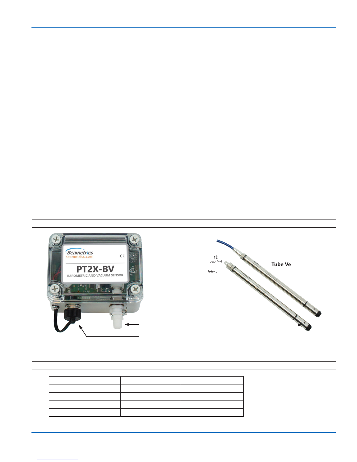
Features
Dimensions
Box 4.3” x 3.1” x 2.6” 11 x 8 x 6.5 cm
Box (including connectors) 4.3” x 3.6” x 2.6” 11 x 9 x 6.5 cm
Tube (cabled) 12.18” x 0.75” diameter 30.9 cm x 1.9 cm diameter
Tube (cableless) 11.93” x 0.75” diameter 30.3 cm x 1.9 cm diameter
Box Version
Communications Port:
• At end of cable on cabled
version
• Inside cap on cableless
version
Air Inlet/Vacuum Port
Communications Port
English Metric
Tube Versions
Air Inlets
Seametrics • 253.872.0284 Page 3 seametrics.com
Page 4

GENERAL INFORMATION
PT2X-BV INSTRUCTIONS
Specications*
Box Enclosure Body Material ABS - IP66/67
Dimensions Box: 4.3” x 3.1” x 2.5” (10.9 x 7.9 x 6.4 cm)
Wire Seal
Material
Tube & Cable Body Material Acetal & 316 stainless or titanium
Dimensions Cabled: 12.18” x 0.75” diameter (30.9 cm x 1.9 cm)
Wire Seal
Material
Weight 0.8 lb. (0.4 kg)
Cable Submersible: polyurethane, polyethylene, or ETFE (4 lb./100 ft., 1.8 kg/30 m)
Environmental IP68, NEMA 6P
Field Connector Standard
Temperature Operating Range Recommended: -15˚ to 55˚C (5˚ to 131˚F)
Storage Range Without batteries: -40˚ to 80˚C (-40˚ to 176˚F)
Power Internal Battery Two lithium ‘AA’ batteries - Expected battery life: 18 months at 15 min. polling interval (may vary do to
Auxiliary 12 Vdc - Nominal, 6-16 Vdc - range
Communication Modbus® RS485 Modbus® RTU, output=32bit IEEE oating point
SDI-12 SDI-12 (ver. 1.3) - ASCII
Logging Memory 4MB - 520,000 records
Logging Types Variable, user-dened, proled
Logging Rates 8x/sec maximum, no minimum
Baud Rates 9600, 19200, 38400
Software Complimentary Aqua4Plus 2.0
Networking 32 available addresses per junction (Address range: 1 to 255)
File Formats .a4d and .csv
Output Channels Temperature Depth/Level¹
Element Digital IC on board Silicon strain gauge transducer, 316 stainless or Hastelloy
Accuracy ±0.5°C — 0° to 55°C (32˚ to 131˚F)
Resolution 0.1˚C 0.0034% FS (typical)
Units Celsius, Fahrenheit, Kelvin PSI, FtH₂O, inH₂O, mmH₂O, mH₂O, inH₂O, cmHg, mmHg, Bars, Bars,
Range -40˚ to 80˚C (-40˚ to 176˚F) 600 to 1100 millibars
Compensated --- 0˚ to 40˚C (32˚ to 104˚F)
Max operating pressure 1.1 x full scale
Burst pressure 2.0 x full scale
*Specications subject to change. Please consult out web site for the most current data (www.seametrics.com). Modbus is a registered trademark of Schneider Electric.
Box and connectors: 4.3” x 3.6” x 2.5” (10.9 x 9.1 x 6.4 cm)
Fluoropolymer and Buna N
Cableless: 11.93” x 0.75” diameter (30.3 cm x 1.9 cm)
Fluoropolymer and PTFE
environmental factors)
±2.0°C — below 0°C (32˚F)
±0.05% FSO (typical, static)
±0.1% FSO (maximum, static)
(B.F.S.L. 20˚C)
kPa
Note: Intended for use in atmosphere—not to be submerged.
Seametrics • 253.872.0284 Page 4 seametrics.com
Page 5

GENERAL INFORMATION
PT2X-BV INSTRUCTIONS
Initial Inspection and Handling
Upon receipt of your PT2X-BV, inspect the shipping package for damage. If any damage is apparent, note the signs of
damage on the appropriate shipping form. After opening the carton, look for concealed damage. If concealed damage
is found, immediately le a claim with the carrier.
Do’s and Don’ts
Box Version
BAROMETRIC AND VACUUM SENSOR
PT2X-BV
BAROMETRIC AND VACUUM SENSOR
PT2X-BV
BAROMETRIC AND VACUUM SENSOR
PT2X-BV
Do handle sensor with
care
Tube version
Don’t install so box or
connector is submerged
Do protect from
excessive sun or heat
Don’t bang or drop on
hard objects
Do install sensor so
the connector end is
kept dry
Don’t scrape cable
over edge of well
May nick or fray the
cable
Seametrics • 253.872.0284 Page 5 seametrics.com
Don’t bend cable
sharply
May weaken internal
wires
Don’t install so
sensor may be
submerged
Don’t support sensor
with the connector
Use a strain relief device
Page 6
INSTALLATION
PT2X-BV INSTRUCTIONS
Connecting External Power
The PT2X-BV comes with two 1.5V AA internal batteries.
If auxiliary power is desired, you can use a 6–16 VDC supply
that can provide 15 mA. Connect to Vaux++ (pin 1 - white)
and Ground (pin 5 - blue) or contact Seametrics for auxiliary
power supplies.
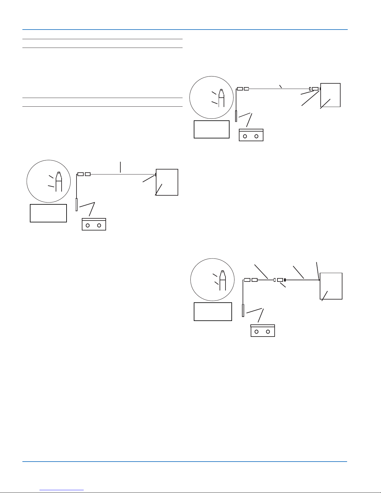
Connecting the PT2X-BV to a Computer
Connect your computer to the PT2X-BV communication
port using Seametrics USB to RS485 adapter. If you have the
tube version, connect to the weather-resistant connector
on the cable or end of the sensor on the cableless version.
(For alternate connection options, see below.)
USB to RS485
Adapter
Screwcap
Sensor
Cableless
Conguration
Sensor
OR
USB Port
PC or Laptop
Computer
Connecting sensor to your computer using
Seametrics USB to RS485 adapter.
Connecting via RS232 Serial Port
Connect the weather-resistant connector to your
computer’s serial port as shown in next column.
Interface Cable
Screwcap
Sensor
OR
Cableless
Conguration
Sensor
RS485/RS232
Adapter
Serial Port
PC or Laptop
Computer
Connecting sensor to your computer using
an RS485/RS232 adapter and an interface cable.
Connecting with a USB/Serial Adapter
USB-to-Serial cables are readily available from many
electronics and computer stores, as well as numerous sites
on the Internet. Seametrics has tested and recommends
the Keyspan USA-19HS. Install as follows:
• Plug into USB port.
• Install the drivers provided with the particular unit.
• Once drivers are installed connect to sensor.
Aqua4Plus 2.0 communicate with the sensor using the USB
to RS485 adapter cable. This cable requires drivers to be
installed on your computer. If you are connected to the
Internet when you rst plug in the cable, it will normally
obtain and install the correct drivers automatically. If this
does not happen, or if you do not have Internet connection,
you can use Aqua4Plus 2.0 to install the drivers.
Alternate Connection Options
Seametrics recommends connecting the sensor to your
computer using the Seametrics USB cable. However, when
using Aqua4Plus 2.0, the sensor can also be connected
using an RS232 serial port or a USB-to-Serial cable, as
described below.
Interface
Screwcap
Sensor
Cableless
Conguration
Cable
OR
Adapter
RS232/RS485
Adapter
Sensor
Connecting sensor to your computer using
a USB to Serial adapter and an interface cable.
USB PortUSB-to-Serial
PC or Laptop
Computer
Seametrics • 253.872.0284 Page 6 seametrics.com
Page 7

INSTALLATION
PT2X-BV INSTRUCTIONS
Connecting to Sensors
Aqua4Plus 2.0 is designed to automatically detect your communication cable and scan for sensors. It is recommended
you connect your USB/RS485 cable to your PC and have the sensor connected before opening Aqua4Plus 2.0.
If your cable and sensor were not connected before opening Aqua4Plus 2.0 simply connect and click Rescan. While
scanning is active you’ll see a green dot ash in the upper right corner of the program. Scanning is complete when this
dot stops ashing.
If your sensor still won’t connect you can expand the Modbus address range under program settings here:
Simply drag the Address Range slider higher up to increase the maximum Modbus address scanned. If you’ve scanned
all the way up through address 255 and still have no connection click Troubleshooting for further troubleshooting or
contact Seametrics Tech Support for assistance.
Click at any time to refresh sensor information.
Seametrics • 253.872.0284 Page 7 seametrics.com
Page 8

INSTALLATION
Earth ground
PT2X-BV INSTRUCTIONS
Wiring and Pin-outs
Pin-out for bulkhead connector on box version and
connector on cableless tube version
Pin Description
1 12 Vdc+
2 Modbus D–
3 Modbus D+
4 SDI-12 Signal
5 Ground
Pin-out for cabled tube version
With connector:
White
Purple
Yellow
Brown
Blue
Shield
1
2
3
4
5
5-Pin
Connector
12 VDC+ (Vaux)
Modbus DModbus D+
SDI-12
12 VDC- (GND)
Without connector:
White
Purple
Yellow
Brown
Blue
Shield
12 VDC+ (Vaux)
Modbus DModbus D+
SDI-12 Signal
12 VDC- (Gnd)
Installing Aqua4Plus 2.0
The PT2X-BV comes with the Aqua4Plus 2.0 host software
that is installed on your PC or laptop. Use this software to
program the datalogger, to retrieve data from the logger,
to view collected data, and to export data to external les
for use with spreadsheets or databases.
Refer to the software manuals for details on installing and
using Aqua4Plus 2.0.
The PT2X-BV can take readings more often than once per
second. This is known as a “continuous rate.” See logging
setup.
Battery Life Calculator
IMPORTANT NOTE for PT2X-BV sensors with rmware 2.13
or higher!
PT2X-BVs with rmware version 2.13 and higher have a
battery life calculator that is set at the factory when batteries
are rst put in the sensor. If the battery life calculator is not
reset, the remaining life information will be incorrect.
If you need to replace the batteries, see the Maintenance
section in this manual for replacement information and for
information on resetting the battery life calculator.
NOTE: If you have a rmware version prior to 2.0, SDI-12
is not available.
Using Without Aqua4Plus 2.0
Most users will use the PT2X-BV with Seametrics Aqua4Plus
2.0 software. However, the PT2X-BV is quite versatile,
communicating via either Modbus® or SDI-12 interfaces,
allowing you to do the following:
• Read a PT2X-BV via Modbus® using your own
software.
• Read a PT2X-BV via SDI-12 protocol.
• Display readings from a PT2X-BV on a panel meter.
If you want to use one of these methods, see page 10.
Seametrics • 253.872.0284 Page 8 seametrics.com
Page 9

INSTALLATION
PT2X-BV INSTRUCTIONS
Installing the Sensor
For Barometric Measurement
Box version
The PT2X-BV box version can be installed in any position;
however, it is tested at the factory in the vertical position.
Therefore, when installing the transmitter outdoors,
Seametrics recommends installing it in a vertical position
to avoid moisture entering the inlet. Seametrics also
recommends installing a sun shield to avoid overheating.
Vertical installation
UP
recommended to avoid
moisture entering the
air inlet
Air Inlet
Tube version
The PT2X-BV tube version can be installed in any position;
however, when it leaves the factory it is tested in the vertical
position. Strapping the sensor body with tie wraps or tape
will not hurt it. Be sure to install so that air inlets will never
be submerged. Seametrics also recommends installing a
sun shield to avoid overheating.
For Vacuum Measurement
If installing a vacuum tube for vacuum measurements,
be sure that the tubing is not collapsible. The box unit is
provided with a detachable Quick-Connect (QC) with a
male 1/8” pipe tting. Attach the tubing to the QC using
an appropriate tube tting for the tubing chosen. Attach
a tting to the inlet male QC designed to seal the tubing
of your choice. Seal the tting to the QC by using sealant
or PTFE tape. Connect the male QC to the inlet QC of the
PT2X-BV and the other end of the tube to the vacuum
source using appropriate ttings.
Settings and Calibration
Settings and calibration values can only be changed when
there are no les stored on the sensor. Be sure to retrieve
any data and then erase the data before continuing.
The temperature channel rarely needs adjustment. If you
think your temperature channel needs adjusting, contact
your service representative.
Before leaving the factory your PT2X-BV was inspected
using precision instruments. However, you can adjust the
settings, if needed, as shown below.
When using a barometric sensor, you may want to change
the channel label at the top of the Settings window to read
“Barometric Pressure.”
Note: Be sure to use the same units for all measurements
on this page. For example, if you have the program set
to display in psi then be sure to enter the barometric
pressure as psi.
-- Computing Oset --
• Using a barometric pressure indicator or other measuring
device, determine the current barometric pressure.
• Enter this value in the REF box..
• Click the Measure button.
• When readings have stabilized to your satisfaction, click
the Accept button in the pop-up box.
-- Applying oset --
• Click the Apply button to apply calculated oset.
• The calculated oset will be transferred to the oset eld
near the top of the window.
• Click OK to save the value to the sensor!!!
Seametrics • 253.872.0284 Page 9 seametrics.com
Page 10

SETTINGS AND CALIBRATION
PT2X-BV INSTRUCTIONS
Sensor Settings
Once connected you’ll see the Sensor screen appear and
display the connected sensor(s) details. Mousing over---
icons will provide tool-tips, mouse over to view sensor
rmware and serial number details.
To change general sensor settings click in the sensor
screen. This allows you to change the following:
Program Settings
To view/change Aqua4Plus 2.0 settings click in the blue
side-bar menu
Under the General Settings tab you can change the default
data folder location. This is where your Reports are saved
to on your PC.
The Zoom Factor slider can be used to adjust the font size
within Aqua4Plus 2.0.
Click to rename the sensor
To change Modbus address and/or Baud Rate simply select
the desired address and/or Baud Rate from the drop down
menus. Sensor will automatically reconnect at new address
and/or Baud Rate
To change the Direct Read output units (for direct Modbus
or SDI12 integration) simply select the desired output
units from the drop down menus. To change Aqua4Plus
2.0 display units scaling see Program Settings.
Sensor Clock can be synced with your PC time or set
manually if desired. To set manually enter your desired
date/time and click Set Time.
When batteries are changed out make sure to reset the
battery information here, simply check the I have just put
in new batteries box and select the battery type that was
installed from the drop down menu.
Uncheck the Allow app to collect anonymous usage
statistics box if you would like to opt out. This information
is used to track Aqua4Plus 2.0 reliability across dierent
system congurations.
Under the Display Units tab you can select your desired
display units for the supported channels. These may be
changed at any time and associated Real-Time readings and
Reports will rescale to the currently selected display unit. To
change Direct Read units scaling see Sensor Settings.
Seametrics • 253.872.0284 Page 10 seametrics.com
Page 11

SETTINGS AND CALIBRATION
Under the Communications tab you can change your
Modbus communication settings. Typically you will only
need to change the address range to connect to sensors
outside of Modbus address 1-10. In certain cases we
may need to change the Retry and Timeout settings to
overcome communication issues on very long, or corroded
cabling. See Troubleshooting section or contact Seametrics
Tech Support for details.
PT2X-BV INSTRUCTIONS
To start real-time readings click Start, readings default to
table view
To switch to Real-time graphing view click the graph
icon
To restore factory default settings click
Real-time Data
Connect to sensor and select the Real-time data tab
Real-time readings default to a 1 second interval for 1
minute, to adjust enter your desired settings here:
Note: Currently this data is not saved and is for viewing
current conditions only. To save the data to sensor memory
see Data Logging section. You can run Real-time Data
while logging is active.
Seametrics • 253.872.0284 Page 11 seametrics.com
Page 12

OPERATION
Data Logging
Select Set Up Logging from the sensor screen
PT2X-BV INSTRUCTIONS
Duration can be set by either number of records
If there are no les currently on the sensor you’ll see the
Set Up Logging button active under the Data Files tab as
well as in the upper menu. Once les have been started/
logged on the sensor they will be displayed under the Data
Files tab.
Setting Up Logging Window
Here you will name your data le and set up the recording
interval and duration of each logging phase. Select your
desired recording interval and duration for each phase,
Aqua4Plus 2.0 will display the available memory at the
bottom of the window.
Or by setting a duration time
When set by number of records the time of the recording
phase will be displayed detailing how long that phase will
run. When set by time, the total number of records for that
phase will be displayed.
If you need to check settings or perform a calibration click
before proceeding with logging setup to switch to the
Settings and Calibration screen.
You may sync the sensor clock with the PC clock when
starting logging by clicking the slider here.
Check the Delayed Start box and enter the desired date/
time you would like logging to start. This is useful for
syncing data when setting up multiple sensors on a site.
Data will start logging at the set date/time rather than
immediately when Start is pressed.
Click to switch between interval and continuous
data recording (PT2X & CT2X only) Select your continuous
rate from the drop down box here.
Seametrics • 253.872.0284 Page 12 seametrics.com
Page 13

OPERATION
PT2X-BV INSTRUCTIONS
Data le name defaults to Test File # and may be re-named
here.
The 3 previous Logging Schedules that were programmed
to a sensor will be listed under the Select Template drop
down menu. There you will also nd pre-programmed
logging schedules such as 24 hour pump test, along with
any custom logging schedules saved by the user.
To save a logging schedule as a template enter desired
settings and click This will add your custom schedule
to the Select Template menu.
Once all the desired settings are made simply click Start to
begin logging.
Data les already downloaded will show in the Reports
column, clicking here will bring you to the reports screen to
view the data. See Reports section for details.
You may only have 1 active data le recording on each
sensor, however you can store multiple les in memory if
desired.
Starting a new le will automatically terminate the active
logging and begin the new logging schedule. Real-time
data is available during active logging.
This will return you to the Sensor screen and your status
will change to Active with the data le displayed under the
Data Files tab. Mouse over an active le to pause, terminate,
download, or view logging setup details.
Seametrics • 253.872.0284 Page 13 seametrics.com
To delete les from memory make sure they have all been
downloaded to Reports. Files are removed from memory
all at once rather than individually.
Once conrmed les are permanently deleted from the
sensor memory.
Page 14

OPERATION
Reports
Data downloaded from your sensor is stored in the Reports
section of Aqua4Plus 2.0 for viewing and editing. The les
will be saved to default data folder on your PC as well. See
Program Settings for default data folder location.
In the main view you’ll see a list of reports sorted by date,
size, or le name as selected here
PT2X-BV INSTRUCTIONS
Click to view data as a table
Click to view data statistics
The Information tab is a new feature allowing users to add
metadata to their reports such as site location, eld notes,
or comments.
You can also search reports by keyword using the search
box
Click on a report to bring up the report details
Reports are displayed in graphing view by default. You can
zoom to specic sections by selecting a section with you
mouse or by adjusting the slider below the graph.
Click to switch to full screen graphing view
Graph saving and export options are available here
The Schedule tab will display the logging setup details for
the report
Click Export to export the report as a .csv le or .a4d le for
distribution or use in 3rd party software.
Click Delete to delete the report from Aqua4Plus 2.0
You can also import .a4d les from compatible sensors into
Aqua4Plus 2.0 by clicking at the top of the Reports
screen.
Seametrics • 253.872.0284 Page 14 seametrics.com
Page 15

OPERATION
Barometric Compensation
PT2X-BV INSTRUCTIONS
For PSIA sensors we’ve built a new barometric compensation
utility into the Reports section. Click on a report to
compensate the data for barometric pressure.
Corresponding barometric les are ltered by date/time
and displayed to the left. Select the barometric le you
would like to use to compensate the report, select either the
Submergence or Depth To Water tab, then click Continue.
Aqua4Plus 2.0 will perform the barometric compensation
and create a new compensated report. Original reports are
retained as uploaded.
Compensated report can then be viewed and exported as
needed.
If compensating for Depth to Water enter your depth
to water reference measurement and the date/time the
measurement was taken (typically taken with a water level
indicator before data is uploaded from the sensor) before
clicking Continue.
Seametrics • 253.872.0284 Page 15 seametrics.com
Page 16

DIRECT READ MODBUS/SDI-12
PT2X-BV INSTRUCTIONS
Power Consideration
If your sensor does not have internal batteries and is not
powered continuously by an auxiliary power supply, then
you must turn power on to the sensor at least two seconds
before a reading is to be taken to allow the sensor to warm
up.
Reading Via Modbus® RTU
Setting Baud Rate
Your PT2X-BV comes congured to communicate at 38,400
baud, with 8 data bits, one stop bit, and no parity. The
sensor can also be set to 19,200 or 9600 baud, if needed
for your application. You must use Aqua4Plus 2.0 to make
baud rate changes. See sensor settings
Taking Measurements
Reading Registers
Read measurements using Modbus function 03 – Read
Holding Registers. Readings are located in two registers
each, starting at address 62592. (PT2X-BV register
addressing is zero based, i.e., starts at zero. If your
equipment uses one based addressing, you will need to
add one to the register addresses.)
Addresses for PT2X-BVs with rmware lower than
2.0
Zero based One based
Pressure 62592 62593
Temperature 62594 62595
Addresses for PT2X-BVs with rmware 2.0 or
higher
Zero based One based
Temperature 62592 62593
Pressure 62594 62595
Measurement Timing
When you request a reading via Modbus, the sensor wakes
up, returns the current values in the registers, and then
starts taking new readings and updating the registers.
After approximately 10 seconds, if no more readings have
been requested, the sensor goes back to sleep.
Because of this, the rst reading you get will be old. If you
are taking readings at intervals of less than 10 seconds,
simply ignore the rst reading — all remaining readings will
be current. On the other hand, if you are taking readings
at intervals of greater than 10 seconds, take a reading,
ignore it, wait one second, take another reading. Record
this second reading.
Data Format
The data is returned as 32-bit IEEE oating-point values,
highword rst, also referred to as big-endian or oat
inverse.
For further information and detailed Modbus examples,
see Seametrics techinical bulletin on Direct Read, available
from our web site at www.seametrics.com.
Seametrics • 253.872.0284 Page 16 seametrics.com
Page 17

DIRECT READ MODBUS/SDI-12
PT2X-BV INSTRUCTIONS
Reading Via SDI-12
Note: The default units setting for pressure is PSI. The default units setting for temperature is Celsius.
To change these, use the Direct Read Units in the Aqua4Plus 2.0 Control Software.
Addressing
Default SDI-12 Address: 1
SDI-12 Command Nomenclature
<a> = Sensor address
{crc} = SDI-12 compatible 3-character CRC
<cr> = ASCII carriage return character
<lf> = ASCII line feed character
highlighted values indicate variable data
SDI-12 Commands
Sensor Identication
<a>I! <a>13 INWUSA PT2X-BV
213ssssssssss<cr><lf>
Acknowledge Active, Address Query
<a>! <a><cr><lf>
?! <a><cr><lf>
Request Response
All SDI-12 requests consist
of a command followed by
a request for values. Some
software or equipment may
combine these, making the
second one unnecessary. Refer
to your software or equipment
documentation for details.
<a>M1! <a>0021<cr><lf>
Address
Command
Request Response
Address
Time until
response
(in seconds)
<a>D0! <a>+7.15863<cr><lf>
Address
Request for
values read
Note: 213 will change to reect current rmware version.
ssssssssss = device serial number
Address
Returned
value(s)
Carriage Return
Linefeed
# of values to
be returned
Carriage Return
Linefeed
Change Address
<a>A<b>! <b><cr><lf> Change address to <b>
Request Measurement
<a>M! <a>0022<cr><lf> Request all measurements
<a>D0! <a>+22.0512+12.0512<cr><lf> Read temperature and pressure
<a>M1! <a>0021<cr><lf> Request temperature measurement only
<a>D0! <a>+22.0512<cr><lf> Read temperature
<a>M2! <a>0021<cr><lf> Request pressure measurement only
<a>D0! <a>12.0512<cr><lf> Read pressure
Seametrics • 253.872.0284 Page 17 seametrics.com
Page 18

DIRECT READ MODBUS/SDI-12
Request Measurement with CRC
<a>MC! <a>0022<cr><lf> Request all measurements with CRC
<a>D0! <a>+22.0512+12.0512{crc}<cr><lf> Read temperature and pressure
<a>MC1! <a>0021<cr><lf> Request temperature measurement only with CRC
<a>D0! <a>+22.0512{crc} <cr><lf> Read temperature
<a>MC2! <a>0021<cr><lf> Request pressure measurement only with CRC
<a>D0! <a>12.0512{crc} <cr><lf> Read pressure
Concurrent Measurement
<a>C! <a>0022<cr><lf> Request all measurements
<a>D0! <a>+22.0512+12.0512<cr><lf> Read temperature and pressure
<a>C1! <a>0021<cr><lf> Request temperature measurement only
<a>D0! <a>+22.0512<cr><lf> Read temperature
PT2X-BV INSTRUCTIONS
<a>C2! <a>0021<cr><lf> Request pressure measurement only
<a>D0! <a>12.0512<cr><lf> Read pressure
Concurrent Measurement with CRC
<a>CC! <a>0022<cr><lf> Request all measurements with CRC
<a>D0! <a>+22.0512+12.0512{crc}<cr><lf> Read temperature and pressure
<a>CC1! <a>0021<cr><lf> Request temperature measurement only with CRC
<a>D0! <a>+22.0512{crc} <cr><lf> Read temperature
<a>CC2! <a>0021<cr><lf> Request pressure measurement only with CRC
<a>D0! <a>12.0512{crc} <cr><lf> Read pressure
For further information and SDI-12 examples, see Seametrics application note, “PT2X SDI-12 Interface Specication”
available from our web site at www.seametrics.com.
Seametrics • 253.872.0284 Page 18 seametrics.com
Page 19

MAINTENANCE
PT2X-BV INSTRUCTIONS
Removing Debris from End Cone (Tube version)
At times mud, silt, or other debris may foul the water inlets
to the pressure element. The end cone can be removed to
clean out the debris.
Twist Open Housing
1. Gently twist o end cone portion only - do not twist
o pressure element!
2. Remove debris. Do not poke anything into the
sensor. This can damage the sensor element and
void the warranty.
3. Replace and retighten the end cone.
Pressure element
Water inlet
End cone
Gently twist o the end cone and carefully remove debris
Changing Batteries
Battery Type: Two 1.5V AA batteries—Lithium or Alkaline
(lithium recommended)
IMPORTANT!
Because changing the batteries involves
opening the water-tight seal, this must be
done in a clean, dry environment to avoid
contamination or moisture damage to the
circuitry.
IF USING ALKALINE BATTERIES
—
PREVENT BATTERY LEAKAGE!
PT2X-BV sensors are typically shipped with
lithium batteries. If, however, you are using
alkaline batteries, be aware that under some
circumstances alkaline batteries can leak,
causing damage to the sensor. To prevent
leakage, the following is recommended. (Does
not apply to lithium batteries.)
• Change the batteries at least every 18
months.
• If the sensor will not be deployed for 3
months or more, remove the batteries.
Sensor
There are no user-serviceable parts, other than the
batteries. If problems develop with sensor stability or
accuracy, contact Seametrics. If the transducers have
been exposed to hazardous materials, do not return them
without notication and authorization.
Cable (Cabled tube version)
Cable can be damaged by abrasion, sharp objects, twisting,
crimping, crushing, or pulling. Take care during installation
and use to avoid cable damage. If a section of cable is
damaged, it is recommended that you send your sensor
back to replace the cable harness assembly.
Battery Life Calculator (Firmware 2.13 or higher)
When changing batteries, it is important to reset the
Battery Life Calculator. If the battery life calculator is not
reset, the remaining life information will be incorrect.
Access the Battery Life Calculator from the Congure
Menu - Battery Information and Reset. If you have put in
new batteries, checkmark the box “I have just put in fresh
batteries.” Click Save and Close.
Be sure to reset the Battery Life Calculator
when changing batteries!
Seametrics • 253.872.0284 Page 19 seametrics.com
Page 20

MAINTENANCE
PT2X-BV INSTRUCTIONS
Box Version
• Remove the four screws in the corners of the top
cover.
• Remove top cover.
• The battery housing is secured using hook and loop
fasteners. Pull gently to release.
• Remove screw on bottom of battery housing and
slide housing open.
• Remove the batteries, taking note of polarity.
• Insert new batteries.
• Replace battery cover and screw.
• Secure on hook and loop fastener.
• Be sure battery switch is On.
• Replace top cover and screws. NOTE: The box is
directionally keyed. Failure to replace the lid
correctly will prevent a tight seal and will result
in water leakage.
On/O
Switch
Tube Version
Tips
• Never place a tool on the sensor body, it is very thin
and will deform causing leaks at o-ring seals and
potentially crushing the circuit board!
• Always twist the sensor body o the top cap
assembly rather than twisting the top cap assembly
o of the sensor body.
• For cabled sensors, always clamp the sensor on the
swaged area when applicable, the shoulder above
it will allow you to press down without the worry of
the sensor slipping out of the clamping device.
• If the sensor body is slippery or you are unable to
grip it hard enough to twist, try a piece of rubber
cabinet liner for additional friction.
There is a black, compressible square ring near the top of
the sensor. This ring acts as a spring to lock the cable in.
This needs to be compressed in order to allow removal
of the top cap. Once this ring is compressed, a gentle
counterclockwise twist is all that is needed to remove the
cable from the sensor body. Compressing the black square
ring does take force, twisting does not.
HousingTop cap
Key Slot
Battery
Housing
Key Tab
Swage Knurling Black square ring
Cabled Sensor
Top cap
Knurling Black square ring
Housing
Cableless Sensor
Care must be taken to compress the black square ring
before attempting to twist the housing. Forceful twisting
of the housing can permanently damage the sensor.
Securing the Sensor
In order to compress the black square ring, the sensor must
be secured so that you can apply downward pressure to
compress the ring. This can be done by holding in your
hand, using a vise, or using pliers, as follows.
Seametrics • 253.872.0284 Page 20 seametrics.com
Page 21

MAINTENANCE
PT2X-BV INSTRUCTIONS
By Hand—cabled version only
1. Tightly grasp the top cap in one hand.
2. Brace your hand against something such as a
table or the ground. (Do not allow the cable to be
pinched against the brace.)
Continue to Removing the Housing on the next page.
With Vise—recommended method
Cabled Sensor
1. If possible, use a set of soft jaws as shown to
prevent marring the surfaces of the top cap
assembly.
2. Place the sensor in a vise clamping gently on the
swaged area. You do not need to clamp the vise
very hard.
Continue to Removing the Housing on the next page.
With Pliers or Vise Grips—good for eld use
Cabled Sensor
1. Grasp the pliers on the swaged area (do not grab
the knurled diameter).
2. Find a hard edge and place the tips or side of the
jaws of the pliers onto this edge as shown. This
will allow you to press down with your weight to
compress the square ring.
Continue to Removing the Housing on the next page.
Cabled Sensor—gripping on swage
Cableless Sensor
1. If possible, use a set of soft jaws as shown to
prevent marring the surfaces of the top cap
assembly.
2. Remove the cableless top cap.
3. Place the sensor in a vise clamping gently on the
knurled area. You do not need to clamp the vise
very hard.
Continue to Removing the Housing on the next page.
Cabled Sensor
Cableless Sensor
1. Leave the cableless cap on in order to protect the
pins inside.
2. Grasp the pliers on the knurled area tightly being
careful to avoid grabbing the knurled cap.
3. Find a hard surface and place the cableless cap
down onto it. This will allow you to press down with
your weight to compress the square ring.
Continue to Removing the Housing on the next page.
Cableless Sensor—gripping on knurled area
Seametrics • 253.872.0284 Page 21 seametrics.com
Cableless Sensor
Page 22

MAINTENANCE
PT2X-BV INSTRUCTIONS
Removing the Housing
1. With your free hand, grasp the sensor body. Press
down to compress the square ring. Twist gently.
Once the body begins to twist, you can stop the
compression action.
2. Finish gently twisting until the sensor body is
removed.
3. Carefully disconnect the wiring connector inside
from the circuit board in the top cap.
Replacing Batteries and Resealing Sensor
1. Gently pull wiring to one side in order to allow
batteries to fall out. Shake gently if needed.
2. Replace batteries with button (+) facing open end.
3. Reinstall wiring connector — it only goes in one
way, so make sure not to force it.
4. Hold the top cap assembly at 90° to the housing
opening as shown. Depress the spring with your
ngertip and tuck the wiring into the cutaway on
the circuit board with your thumb to protect it while
being installed back into the housing.
Wires tucked into slot and spring tucked into housing
5. Rotate the top cap assembly into the opening in the
housing being very careful not to nick or pinch any
wires.
Pull wires gently to the side to allow battery removal
Connector connected properly
Push top cap in before twisting and locking
6. Gently press down until the assembly stops
and then twist it into place. It will click in and
decompress the gasket when it is fully engaged.
Properly completed—black ring uncompressed
Seametrics • 253.872.0284 Page 22 seametrics.com
Page 23

TROUBLESHOOTING
Problem Probable Causes Things to try…
PT2X-BV INSTRUCTIONS
Software will not
Loose cable Make sure all cable connections are secure
communicate with
sensor
Contacts in connector loose Be sure all wires are securely fastened inside the
USB driver not installed See Connecting the PT2X-BV to a Computer in
Incorrect USB or COM port selected If using Aqua4Plus, be sure USB is selected in
SEE ALSO ERRATIC READINGS BELOW
Erratic readings Poor connection due to moisture between
contacts in connector
Loose or broken wires in connector Repair or return for evaluation and repair
Damaged cable, cracked or fraying Replace cable
round connector
the Installation section or see the USB/RS485
Adapter Installation application note on our
web site.
the dropdown box on the tool bar or the correct
COM port if using an alternate connection
method. (Aqua4Plus Lite automatically uses only
the USB connection.)
Dry thoroughly. Be sure desiccant is fresh (see
Maintenance section).
Oscillating readings
over time (usually
0.5 to 1.5 feet of
water)
Zero readings when
pressurized
Moisture in the unit Return for evaluation and repair
Damaged transmitter Return for evaluation and repair
Plugged vent tube (if using a vented unit) Be sure desiccant tube is installed. Test by
gently applying a small amount of pressure
to the end of the desiccant tube and seeing
if this aect the transmitter reading. If it does
not, then the vent tube is plugged. Return for
evaluation and repair.
Actual water level changes in the aquifer
itself in response to barometric pressure
changes. This eect can occur in tight
You will need to record barometric pressure as
well as the water level pressure and compensate
the data
formations where the transmitter will
immediately pick up barometric changes
but the the aquifer will not.
Poor connection due to moisture between
contacts in connector
Dry thoroughly. Be sure desiccant is fresh (see
Maintenance section).
Loose or broken wires in connector Repair or return for evaluation and repair
Damaged cable, broken, cracked, or fraying Replace cable
No apparent damage upon visual inspection Return for evaluation and repair
Seametrics • 253.872.0284 Page 23 seametrics.com
Page 24

LIMITED WARRANTY/DISCLAIMER - Seametrics PT2X-BV
BAROMETRIC/VACUUM SMART SENSOR
A. Seller warrants that products manufactured by Seller when properly installed, shall be free from defects in material
and workmanship. Seller’s obligation under this warranty shall be limited to replacing or repairing the part or parts or,
at Seller’s option, the products which prove defective in material or workmanship within TWO (2) years from the date
of delivery, provided that Buyer gives Seller prompt notice of any defect or failure and satisfactory proof thereof. Any
defective part or parts must be returned to Seller’s factory or to an authorized service center for inspection. Buyer
will prepay all freight charges to return any products to Seller’s factory, or any other repair facility designated by Seller.
Seller will deliver replacements for defective products to Buyer (ground freight prepaid) to the destination provided in
the original order. Products returned to Seller for which Seller provides replacement under this warranty shall become
the property of Seller.
This limited warranty does not apply to lack of performance caused by abrasive materials, corrosion due to aggressive
uids, mishandling or misapplication. Seller’s obligations under this warranty shall not apply to any product which (a)
is normally consumed in operation, or (b) has a normal life inherently shorter than the warranty period stated herein.
In the event that equipment is altered or repaired by the Buyer without prior written approval by the Seller, all warranties
are void. Equipment and accessories not manufactured by the Seller are warranted only to the extent of and by the
original manufacturer’s warranty.
THE FOREGOING WARRANTIES ARE IN LIEU OF ALL OTHER WARRANTIES, WHETHER ORAL, WRITTEN, EXPRESSED,
IMPLIED OR STATUTORY. IMPLIED WARRANTIES OF FITNESS AND MERCHANTABILITY SHALL NOT APPLY. SELLER’S
WARRANTY OBLIGATIONS AND BUYER’S REMEDIES THEREUNDER (EXCEPT AS TO TITLE) ARE SOLELY AND EXCLUSIVELY
AS STATED HEREIN. IN NO CASE WILL SELLER BE LIABLE FOR CONSEQUENTIAL DAMAGES, LABOR PERFORMED IN
CONNECTION WITH REMOVAL AND REPLACEMENT OF THE SENSOR SYSTEM, LOSS OF PRODUCTION OR ANY OTHER
LOSS INCURRED BECAUSE OF INTERRUPTION OF SERVICE. A NEW WARRANTY PERIOD SHALL NOT BE ESTABLISHED
FOR REPAIRED OR REPLACED MATERIAL, PRODUCTS OR SUPPLIES. SUCH ITEMS SHALL REMAIN UNDER WARRANTY
ONLY FOR THE REMAINDER OF THE WARRANTY PERIOD ON THE ORIGINAL MATERIALS, PRODUCTS OR SUPPLIES.
B. With respect to products purchased by consumers in the United States for personal use, the implied warranties
including but not limited to the warranties of merchantability and tness for a particular purpose, are limited to
twentyfour (24) months from the date of delivery.
Some states do not allow limitations on the duration of an implied warranty, so the above limitation may not apply to
you. Similarly, some states do not allow the exclusion or limitation of consequential damages, so the above limitation
or exclusion may not apply to you. This limited warranty gives you specic legal rights; however, you may also have
other rights which may vary from state to state.
Seametrics • 19026 72nd Avenue South • Kent, Washington 98032 • USA
(P) 253.872.0284 • (F) 253.872.0285 • 1.800.975.8153 • seametrics.com
LT-14331r8 20180227
2/27/18
 Loading...