

Page 1
Precision Environmental Sensors
I
d
C
For Sales & Service Contact
2650 E. 40th Ave. • Denver, CO 80205
Phone 303-320-4764 • Fax 303-322-7242
1-800-833-7958
www.geotechenv.com
An ON
CON Brand
PS98i/PS9800
Submersible Pressure Transmitter
Instructions
For PSIG
sensors, refer
to page 7
regarding
desiccant
o
m
e
i
p
f
PROUDLY
MADE
IN THE
USA
i
t
r
e
C
ISO
9001:2008
a
n
y
use!
Page 2

TABLE OF CONTENTS
PS98I/PS9800 INSTRUCTIONS
General Information
General Information ...................................................................................................................................................Page 3
Dimensions ....................................................................................................................................................................Page 3
Specications ................................................................................................................................................................Page 4
How Pressure Sensors Work....................................................................................................................................Page 5
Initial Inspection and Handling ..............................................................................................................................Page 6
Do’s and Don’ts ............................................................................................................................................................Page 6
Installation
Installing the Sensor ...................................................................................................................................................Page 7
Cable Wiring ..................................................................................................................................................................Page 7
Desiccant Use ................................................................................................................................................................Page 7
Grounding Issues .........................................................................................................................................................Page 7
Operation
Operation ........................................................................................................................................................................Page 8
Maintenance
Desiccant Tubes ...........................................................................................................................................................Page 9
Removing Debris from End Cone ..........................................................................................................................Page 9
Sensor ..............................................................................................................................................................................Page 9
Cable .................................................................................................................................................................................Page 9
Troubleshooting
Problems .........................................................................................................................................................................Page 10
Probable Causes ...........................................................................................................................................................Page 10
Things to Try ..................................................................................................................................................................Page 10
Warranty
Seametrics Limited Warranty ..................................................................................................................................Page 11
Seametrics • 253.872.0284 Page 2 seametrics.com
Page 3
GENERAL INFORMATION
PS98i/PS9800 INSTRUCTIONS
The PS98i/PS9800 pressure transmitters are rugged and
accurate with great noise immunity, transient protection,
and thermal performance.
These pressure sensors have been designed to provide
trouble-free submersible operation in liquid environments.
Pressure is measured with an extremely rugged and
stable piezo-electric, media isolated pressure element and
calibrated with well established calibration procedures and
NIST traceable equipment.
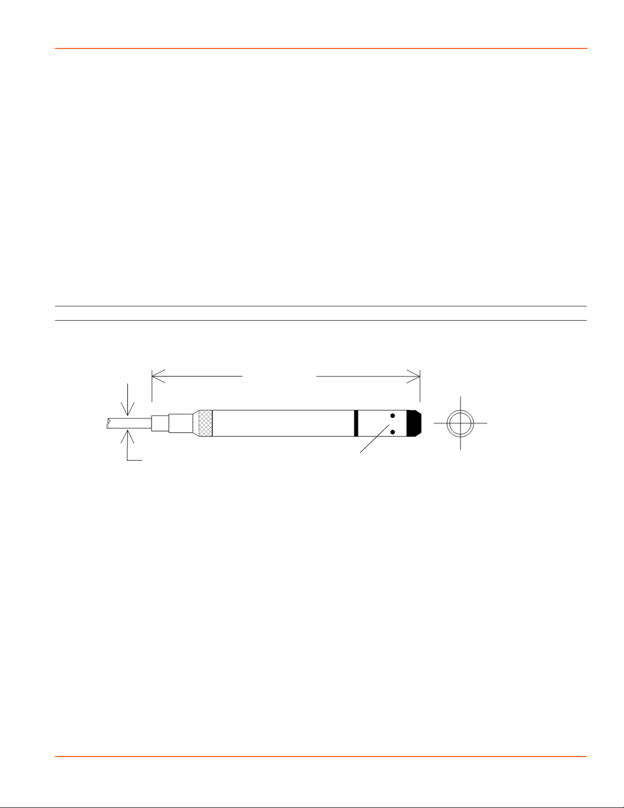
Dimensions
8.44” (21.4 cm)
These sensors are thermally compensated, making them
great where water temperatures vary, as they are thermally
stable (2% over 50 degrees standard).
Both the PS98i and the PS9800 measure pressure, while the
PS9800 can optionally be factory congured to measure
temperature, also.
These industry standard, 2-wire, 4-20mA devices oer
reverse polarity protection, under- and over-current
limitation, and built-in transient protection.
0.28” (0.7 cm)
Water inlets
Diameter
0.75” (1.9cm)
Seametrics • 253.872.0284 Page 3 seametrics.com
Page 4
GENERAL INFORMATION
PS98I/PS9800 INSTRUCTIONS
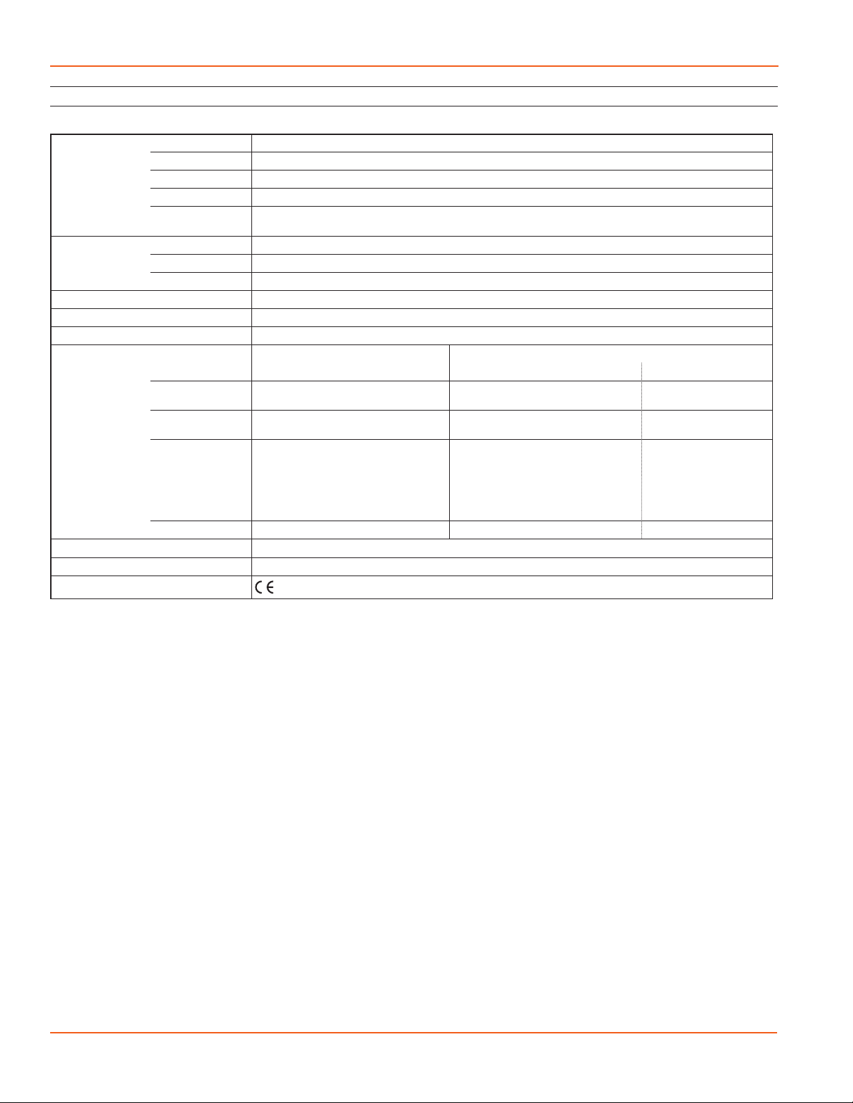
Specications*
Housing Weight 0.8 lb. (0.4 kg)
Length 8.44” (21.4 cm)
Diameter 0.75” (1.9 cm)
Body Material Acetal and 316 stainless or optional titanium
Wire Seal
Material
Cable Cable Submersible: Polyurethane, polyethylene, or ETFE available
Desiccant 1-3 mm indicating silica gel
Field Connector Available as an option
Operating Temperature Range Recommended: -5˚ to 70˚C (23˚ to 158˚F) Requires freeze protection if using in water below freezing.
Transmitter Voltage 9-24Vdc (100ms warmup)
Output 4-20mA
Output Channels PS98i PS9800
Element Silicon strain gauge transducer, 316
Accuracy ±0.25% FSO (static, B.F.S.L. 20˚C) ±0.1% FSO (static, B.F.S.L. 20˚C) ±0.3˚C (typical at 25˚C)
Range
Compensated 0˚ to 50˚C (32˚ to 122˚F) 0˚ to 50˚C (32˚ to 122˚F) ---
Max operating pressure 1.1 x FS
Burst pressure 3.0 x FS (for >300 psi (650ft, 200m) contact Seametrics representative)
Regulatory
*Specications subject to change. Please consult out web site for the most current data (seametrics.com).
1 Higher pressure ranges available upon request
2 Depth range for absolute sensors has 14.7 PSI subtracted to give actual depth allowed.
Fluoropolymer and PTFE
Pressure¹ Pressure¹ Temperature (Optional)
stainless or Hastelloy
Silicon strain gauge transducer, 316
stainless or Hastelloy
Thermistor
±0.75˚C (max. at 25˚C)
Gauge PSI: 1, 5, 15, 30, 50, 100, 300
FtH₂O: 2.3, 12, 35, 69, 115, 231, 692
mH₂O: 0.7, 3.5, 10.5, 21, 35, 70, 210
Absolute² PSI: 30, 50, 100, 300
FtH₂O: 35, 81, 196, 658
mH₂O: 10, 24, 59, 200
Gauge PSI: 5, 15, 30, 50, 100, 300
FtH₂O: 2.3, 12, 35, 69, 115, 231, 692
mH₂O: 0.7, 3.5, 10.5, 21, 35, 70, 210
Absolute² PSI: 30, 50, 100, 300
FtH₂O: 35, 81, 196, 658
mH₂O: 10, 24, 59, 200
0˚ to 50˚C (32˚ to 122˚F)
Seametrics • 253.872.0284 Page 4 seametrics.com
Page 5

GENERAL INFORMATION
PS98i/PS9800 INSTRUCTIONS
How Pressure Sensors Work
Liquids and gasses do not retain a xed shape. Both
have the ability to ow and are often referred to as
uids. One fundamental law for a uid is that the uid
exerts an equal pressure in all directions at a given level.
Further, this pressure increases with an increasing depth of
“submergence”. If the density of a uid remains constant
(noncompressible...a generally good assumption for water
at “normal” pressures and temperatures), this pressure
increases linearly with the depth of “submergence”.
We are all “submerged” in the atmosphere. As we increase
our elevation, the pressure exerted on our bodies decreases
as there is less of this uid above us. It should be noted
that atmospheric pressure at a given level does vary
with changes in the weather. One standard atmosphere
(pressure at sea level at 20º C) is dened to be 14.7 PSI
(pounds per square inch).
There are several methods to reference a pressure
measurement. Absolute pressure is measured with respect
to an ideal vacuum (no pressure). Gauge pressure is the
most common way we express pressure in every day life
and is the pressure exerted over and above atmospheric
pressure. With this in mind, gauge pressure (Pg) can be
expressed as the dierence between the absolute pressure
(Pa) and atmospheric pressure (Patm):
Water Line
P = Patm + kd
A
Patm
d
“A”
Pressure Diagram: See Detail A.
Pg = Pa - Patm.
To measure gauge pressure, atmospheric pressure is
subjected to one side of the system and the pressure to be
measured is subjected to the other. The result is that the
dierential (gauge pressure) is measured. A tire pressure
gauge is a common example of this type of device.
Recall that as the level of submergence increases (in a
noncompressible uid), the pressure increases linearly.
Also, recall that changes in weather cause the absolute
atmospheric pressure to change. In water, the absolute
pressure (Pa) at some level of depth (d) is given as follows:
Pa = Patm + kd
where k is simply a constant
(i.e.: 2.307 feet of water = 1 PSI)
Seametrics’ standard gauge submersible pressure
devices utilize a vent tube in the cable to allow the
device to reference atmospheric pressure. The resulting
gauge pressure measurement reects only the depth of
submergence. That is, the net pressure on the diaphragm
is due entirely to the depth of submergence.
Absolute pressure is given as Pa = Patm + kd
(where k is 2.307 feet of water)
Seametrics • 253.872.0284 Page 5 seametrics.com
Page 6

GENERAL INFORMATION
PS98I/PS9800 INSTRUCTIONS
Initial Inspection and Handling
Upon receipt of your smart sensor, inspect the shipping package for damage. If any damage is apparent, note the signs
of damage on the appropriate shipping form. After opening the carton, look for concealed damage, such as a cut cable.
If concealed damage is found, immediately le a claim with the carrier.
Check the etched label on the sensor to be sure that the proper range and type were provided. Also check the label
attached to the cable at the connector end for the proper cable length.
Do’s and Don’ts
Do handle sensor with
care
Do store sensor in a
dry, inside area when
not in use
Do install a desiccant
tube if using a gauge
sensor
Don’t drop into well
Lower gently to prevent
damage
Seametrics • 253.872.0284 Page 6 seametrics.com
Don’t scrape cable
over edge of well
May nick or fray the
cable
Don’t bend cable sharply
May close o vent tube
and/or weaken internal
wires
Don’t support sensor
with the connector
Use a strain relief device
Page 7

INSTALLATION
PS98i/PS9800 INSTRUCTIONS
Installing the Sensor
The PS98i/PS9800 measures pressure. The most common
application is measuring liquid levels in wells and tanks.
In order to do this, the sensor must be installed below
the water level at a xed depth. The installation depth
depends on the range of the sensor. One (1) PSI is equal to
approximately 2.31 feet of water. If you have a 5 PSI sensor,
the range is 11.55 feet of water and the sensor should not
be installed at a depth below 11.55 feet. If the sensor is
installed below its maximum range, damage may result to
the sensor and the output reading will not be correct.
• Lower the sensor to the desired depth.
• Fasten the cable to the well head using a weather
proof strain-relief system. When securing a vented
cable, make sure not to pinch the cable too tightly
or the vent tube inside the cable jacket may be
sealed o.
• Take a measurement to insure the sensor is not
installed below its maximum range.
• It is recommended that several readings be taken to
ensure proper operation after installation.
If a gauge unit is to be left in the well for a long-term
monitoring application, a desiccant tube must be installed
to prevent condensation in the cable vent tube. Water in
the vent tube will case inaccurate readings and, in time, will
work its way into the transmitter and damage it.
The sensor can be installed in any position; however, when
it leaves the factory it is calibrated in the vertical position.
Strapping the sensor body with tie wraps or tape will not
hurt it. Seametrics can provide an optional 1/4” NPT input
adapter which is interchangeable with the standard end
cone for those applications where it is necessary to directly
attach the sensor to a pipe, tank, or other pipe port. If the
sensor is being installed in a uid environment other than
water, be sure to check the compatibility of the uid with
the wetted parts of the sensor.
Cable Wiring
PS98i
Pressure
Shield Ground Ground Ground
White V+ V+ V+
Blue Signal return Signal return Signal return (pressure)
Yellow -- -- V+ (temperature)
Purple -- -- Signal return (temperature)
PS9800
Pressure
PS9800
Pressure & Tempturature
(pressure)
Desiccant Use
On vented sensors a desiccant tube prevents moisture in
the air from being sucked into the vent tube, which can
cause erratic readings and sensor damage.
The desiccant tube is lled with blue silica gel beads. A
locking barb and a hydrophobic water lter are attached to
the end of the desiccant tube. This lter prolongs the life of
the desiccant as much as three times over a desiccant tube
without the lter.
Install the sensor so that the desiccant tube will not ood
or lie in water.
The desiccant is a bright blue color when active and dry. See
Maintenance section for care and changing of desiccant.
Grounding Issues
It is commonly known that when using electronic
equipment, both personnel and equipment need to be
protected from high power spikes that may be caused by
lightning, power line surges, or faulty equipment. Without
a proper grounding system, a power spike will nd the path
of least resistance to earth ground—whether that path is
through sensitive electronic equipment or the person
operating the equipment. In order to ensure safety and
prevent equipment damage, a grounding system must be
used to provide a low resistance path to ground.
When using several pieces of interconnected equipment,
each of which may have its own ground, problems with
noise, signal interference, and erroneous readings may be
noted. This is caused by a condition known as a Ground
Loop. Because of natural resistance in the earth between
the grounding points, current can ow between the points,
creating an unexpected voltage dierence and resulting
erroneous readings.
The single most important step in minimizing a ground
loop is to tie all equipment (sensors, data loggers, external
power sources, and any other associated equipment)
to a single common grounding point. Seametrics
recommends connecting the shield to ground at the
top end. This is especially important in a pumping well
to avoid failure.
Seametrics • 253.872.0284 Page 7 seametrics.com
Page 8

OPERATION
PS98I/PS9800 INSTRUCTIONS
The PS98i/PS9800 submersible pressure transmitters are
industry standard two-wire, 4-20 mA devices, oering
improved noise immunity, thermal performance and
transient protection. In addition to reverse polarity
protection, under-current and over-current limitation are
featured on both transmitter channels.
As mentioned above, the PS98i/PS9800 transmitters
are current loop devices. This means that changes in
pressure imposed on the stainless steel diaphragm result
in proportional changes in current. The excitation source
(DC supply or data logger) supplies the power but the
transmitter actually controls how much current ows as
long as the excitation specications (e.g., voltage level) are
met.
Compute these m and b values as follows:
m = (Total range of measurement in your units) / 16
For example: if you want to measure 0–15 psi:
15 / 16 = 0.9375
For a standard gauge pressure device, there is zero pressure
on the diaphragm when above the surface of the liquid.
This zero pressure is converted to a current ow of 4 mA.
As the transmitter is lowered into the liquid, the amount of
current that ows increases linearly (with increasing depth)
to 20 mA when the maximum rated pressure (thus depth)
is reached. That is, there is a straight line relationship
between pressure (thus depth of submergence) and the
amount of current that ows. A data logger therefore
can apply power, measure the amount of current that is
owing and convert that to the depth of submergence
using a multiplier and oset (m and b, respectively, for a
y = mx + b straight line) which are preset in the logger by
the user.
b = m * 4 * (–1)
Using our 0–15 psi example above, this would be
0.9375 * 4 * (–1) = –3.75
Seametrics • 253.872.0284 Page 8 seametrics.com
Page 9

MAINTENANCE
PS98i/PS9800 INSTRUCTIONS
Desiccant Tubes
On vented sensors, inspect the desiccant tube at least once
every two months. The desiccant tube prevents moisture
in the air from being sucked into the vent tube, which can
cause erratic readings and sensor damage.
The desiccant tube is lled with blue silica gel beads. A
locking barb and a hydrophobic water lter are attached to
the end of the desiccant tube. This lter prolongs the life of
the desiccant as much as three times over a desiccant tube
without the lter.
Install the sensor so that the desiccant tube and cable
connector will not ood or lie in water.
The desiccant is a bright blue color when active and dry.
As moisture is absorbed the color will begin to fade,
becoming a light pink, which indicates full saturation and
time to replace. Replacement desiccant and hydrophobic
lters can be purchased from Seametrics.
To Change the Desiccant:
• Pulling gently remove the black tube tting from
the clear desiccant tube.
• Using needle-nose pliers, remove the dark gray
foam plug. Do not discard the plug.
• Dump out the old desiccant beads and rell with
new desiccant beads – tapping desiccant tube
frequently during relling to ensure that the beads
are fully seated in tube.
• Push the foam plug back into the tube.
• Reinsert the black tting.
Removing Debris from End Cone
At times mud, silt, or other debris may foul the water inlets
to the pressure element. The end cone can be removed to
clean out the debris.
Twist Open Housing
1. Gently twist o end cone portion only - do not twist
o pressure element!
2. Remove debris. Do not poke anything into the
sensor. This can damage the sensor element and
void the warranty.
3. Replace and retighten the end cone.
Pressure element
Water inlet
End cone
Set Screw Housing
1. Remove the two set screws at the bottom of the
housing tube, using a 1/16” allen wrench.
2. Gently remove the end cone.
3. Remove debris. Do not poke anything into the
sensor. This can damage the sensor element and
void the warranty.
4. Replace the end cone and secure with set screws.
Pressure element
Water inlet
Set screw
End cone
Sensor
There are no user-serviceable parts. If problems develop
with sensor stability or accuracy, contact Seametrics. If the
transducers have been exposed to hazardous materials, do
not return them without notication and authorization.
Cable
Cable can be damaged by abrasion, sharp objects, twisting,
crimping, crushing, or pulling. Take care during installation
and use to avoid cable damage. If a section of cable is
damaged, it is recommended that you send your sensor
back to replace the cable harness assembly.
Seametrics • 253.872.0284 Page 9 seametrics.com
Page 10

TROUBLESHOOTING
Problem Probable Causes Things to try…
PS98I/PS9800 INSTRUCTIONS
Erratic readings Poor connection due to moisture between
contacts in connector
Loose or connection broken wires Repair or return for evaluation and repair
Damaged cable, cracked or fraying Replace cable
Moisture in the unit Return for evaluation and repair
Damaged transmitter Return for evaluation and repair
Improper grounding See section on grounding on in the Installation
Oscillating readings
Plugged vent tube (if using a vented unit) Be sure desiccant tube is installed. Test by
over time (usually
0.5 to 1.5 feet of
water)
Actual water level changes in the aquifer
itself in response to barometric pressure
changes. This eect can occur in tight
formations where the transmitter will
immediately pick up barometric changes
but the the aquifer will not.
Dry thoroughly. Be sure desiccant is fresh (see
Maintenance section).
section
gently applying a small amount of pressure
to the end of the desiccant tube and seeing
if this aect the transmitter reading. If it does
not, then the vent tube is plugged. Return for
evaluation and repair.
You will need to record barometric pressure as
well as the water level pressure and compensate
the data
Zero readings when
pressurized
Poor connection due to moisture between
contacts in connector
Dry thoroughly. Be sure desiccant is fresh (see
Maintenance section).
Loose or broken connection wires Repair or return for evaluation and repair
Damaged cable, broken, cracked, or fraying Replace cable
No apparent damage upon visual inspection Return for evaluation and repair
Seametrics • 253.872.0284 Page 10 seametrics.com
Page 11

SEAMETRICS LIMITED WARRANTY
PS98i/PS9800 INSTRUCTIONS
The limited warranty set forth below is given by Seametrics, with respect to Seametrics and Seametrics brand products purchased
in the United States of America.
Seametrics warrants that products manufactured by Seametrics, when delivered to you in new condition in their original containers
and properly installed, shall be free from defects in material and workmanship. Seametrics products are warranted against
defects for a period of two (2) years from date of installation, with proof of install date. If no proof of install date can be
provided, warranty period will be two (2) years from date of shipment from Seametrics, as dened on Seametrics’ invoice.
Seametrics’ obligation under this warranty shall be limited to replacing or repairing the part or parts, or, at Seametrics’ option, the
products, which prove defective in material or workmanship. The following are the terms of Seametrics’ limited warranty:
a. Buyer must give Seametrics prompt notice of any defect or failure and satisfactory proof thereof.
b. Any defective part or parts must be returned to Seametrics’ factory or to an authorized service center for inspection.
c. Buyer will prepay all freight charges to return any products to Seametrics’ factory, or another repair facility. as designated by
Seametrics.
d. Defective products, or parts thereof, which are returned to Seametrics and proved to be defective upon inspection, will be
repaired to factory specications.
e. Seametrics will deliver repaired products or replacements for defective products to the buyer (ground freight prepaid) to the
destination provided in the original order.
f. Products returned to Seametrics for which Seametrics provides replacement under this warranty shall become the property
of Seametrics.
g. This limited warranty covers all defects encountered in normal use of Seametrics products, and does not apply to the
following cases:
i. Loss of or damage to Seametrics product due to abuse, mishandling, or improper packaging by buyer
ii. Failure to follow operating, maintenance, or environmental instructions prescribed in Seametrics’ instruction manual
iii. Products not used for their intended purpose
iv. Alterations to the product, purposeful or accidental
v. Electrical current uctuations
vi. Corrosion due to aggressive materials not approved for your specic product
vii. Mishandling, or misapplication of Seametrics products
viii. Products or parts that are typically consumed during normal operation
ix. Use of parts or supplies (other than those sold by Seametrics) which cause damage to the products, or cause
abnormally frequent service calls or service problems
h. A new warranty period shall not be established for repaired or replaced material, products, or supplied. Such items shall
remain under warranty only for the remainder of the warranty period on the original materials, products, or supplies.
i. In the event that equipment is altered or repaired by the buyer without prior written approval by Seametrics, all warranties
are void. Damage caused by equipment or accessories not manufactured by Seametrics may void the product’s warranty.
j. SOFTWARE: The Seller grants the user a non-exclusive license to use Seametrics’ software, according to the following
limitations and conditions:
i. The user may install the software on one or more desktop or laptop computers.
ii. All title and intellectual rights to the software are owned by Seametrics.
iii. No copies may be made or distributed except as described above.
iv. The user may not modify or reverse-engineer the software.
THE FOREGOING WARRANTY IS IN LIEU OF ALL OTHER WARRANTIES, WHETHER ORAL, WRITTEN, EXPRESSED, IMPLIED OR STATUTORY.
NO IMPLIED WARRANTY, INCLUDING ANY IMPLIED WARRANTY OF MERCHANTABILITY OR FITNESS FOR A PARTICULAR PURPOSE,
APPLIED TO THE PRODUCTS AFTER THE APPLICABLE PERIOD OF THE EXPRESS LIMITED WARRANTY STATED ABOVE, AND NO OTHER
EXPRESS WARRANTY OR GUARANTY, EXCEPT AS MENTIONED ABOVE, GIVEN BY ANY PERSON OR ENTITY WITH RESPECT TO THE
PRODUCTS, SHALL BIND SEAMETRICS. SEAMETRICS SHALL NOT BE LIABLE FOR LOSS OF REVENUES, OR PROFITS, OR INCONVENIENCES,
EXPENSE FOR SUBSTITUTE EQUIPMENT OR SERVICE, STORAGE CHARGES, LOSS OF DATA, OR ANY OTHER SPECIAL, INCIDENTAL, OR
CONSEQUENTIAL DAMAGE CAUSED BY THE USE OR MISUSE OF, OR INABILITY TO USE THE PRODUCTS, REGARDLESS OF THE LEGAL
THEORY ON WHICH THE CLAIM IS BASED, AND EVEN IF SEAMETRICS HAS BEEN ADVISED OF THE POSSIBILITY OF SUCH DAMAGES. IN NO
EVENT SHALL RECOVERY OF ANY KIND AGAINST SEAMETRICS BE GREATER IN AMOUNT THAN THE PURCHASE PRICE OF THE PRODUCT
SOLD BY SEAMETRICS AND CAUSING THE ALLEGED DAMAGE. WITHOUT LIMITING THE FOREGOING, YOU ASSUME ALL RISK OF LIABILITY
FOR LOSS, DAMAGE, OR INJURY TO YOU AND YOUR PROPERTY AND TO OTHERS AND THEIR PROPERTY ARISING OUT OF USE OR MISUSE
OF, OR INABILITY TO USE THE PRODUCTS NOT CAUSED DIRECTLY BY THE NEGLIGENCE OF SEAMETRICS.
SOME STATES DO NOT ALLOW LIMITATIONS ON THE DURATION OF AN IMPLIED WARRANTY, SO THE ABOVE LIMITATIONS MAY NOT
APPLY TO YOU. SIMILARLY, SOME STATES DO NOT ALLOW THE EXCLUSION OR LIMITATIONS OF CONSEQUENTIAL DAMAGE, SO THE
ABOVE LIMITATION OR EXCLUSION MAY NOT APPLY TO YOU. THIS LIMITED WARRANTY GIVES YOU SPECIFIC LEGAL RIGHTS; HOWEVER,
YOU MAY ALSO HAVE OTHER RIGHTS WHICH MAY VARY FROM STATE TO STATE.
Seametrics • 253.872.0284 Page 11 seametrics.com
Page 12

Seametrics • 19026 72nd Avenue South • Kent, Washington 98032 • USA
(P) 253.872.0284 • (F) 253.872.0285 • 1.800.975.8153 • seametrics.com
LT-14399r13 20180306
3/6/2018
 Loading...