

Page 1
d
C
PE202
Low Flow Magmeter
Instructions
o
m
e
i
p
f
PROUDLY
MADE
IN THE
USA
i
t
r
e
C
ISO
9001:2008
a
n
y
Page 2

TABLE OF CONTENTS
General Information
General Information ...................................................................................................................................................Page 3
Features ..........................................................................................................................................................................Page 3
Specications ................................................................................................................................................................Page 4
Dimensions ....................................................................................................................................................................Page 5
Pressure Drop Curve ...................................................................................................................................................Page 5
Installation
Positioning......................................................................................................................................................................Page 6
Mounting ........................................................................................................................................................................Page 6
Piping ...............................................................................................................................................................................Page 6
Power Supply .................................................................................................................................................................Page 6
Grounding ......................................................................................................................................................................Page 6
Connections
General Connection Information ...........................................................................................................................Page 7
Pulse Output Only with FT520 ................................................................................................................................Page 7
4-20 mA Device and FT430/440 with Single Power Supply ........................................................................Page 7
Dual Power Supply with Loop Isolation ..............................................................................................................Page 7
Operation
General Operation Information..............................................................................................................................Back
PE202 INSTRUCTIONS
Troubleshooting
Problem ...........................................................................................................................................................................Back
Probably Causes ...........................................................................................................................................................Back
Things to Try ..................................................................................................................................................................Back
Seametrics • 253.872.0284 Page 2 seametrics.com
Page 3
GENERAL INFORMATION
PE202 INSTRUCTIONS
The PE202 magmeter is designed for low-ow chemical
injection or difcult-to-meter applications with pulsating
metering pumps in 3/4” to 1/4” pipe/tube. The housing is
made of sturdy splashproof HDPE plastic.
With no moving parts, the PE202 can handle uids
containing particulate matter without clogging or jamming,
keeping maintenance at a minimum. With no metallic parts
(100% PVDF body and PVDF carbon ber-lled electrodes),
the meter is corrosion-resistant and compatible with a
wide range of chemicals (consult factory for chemicals and
concentrations). Accuracy is maintained with conductive
uids (>20 microSiemens) of varying viscosities and
densities.
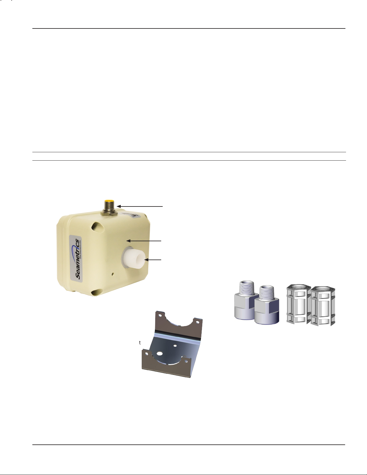
FEATURES
8-pin circular bulkhead connector, 20 foot (6 meter) cable provided
The PE meter is compact enough to t most pump/injection
systems. With zero straight pipe required after an elbow,
it can be easily mounted in tight spaces. The mounting
bracket adds stability.
The PE meter has an optoisolated current sinking pulse
output that can be connected to the Seametrics FT430/440
rate/total display or FT520 batch processor, as well as an
optoisolated 4-20 mA current loop for analog devices.
Outputs and power are provided through a cable with
8-pin female circular connector.
Mounting bracket
Internals made of chemical and corrosion-resistant PVDF
Sturdy HDPE housing
½” male NPT
ttings standard
Threaded male or female NPT adapters
can be purchased separately
(available in PVDF and PP)
(Female NPT available in 1/2” only)
Seametrics • 253.872.0284 Page 3 seametrics.com
Page 4

GENERAL INFORMATION
PE202 INSTRUCTIONS
Specications*
Pipe Size 3/4”, 1/2”, 3/8”, 1/4” **
Fittings 1/2” NPT ttings standard in 3/4” or 3/8” owbody. NPT threaded adapters available for above
Materials Body PVDF
Electrodes PVDF carbon ber lled
Ground PVDF carbon ber lled
Housing HDPE with 25% glass
Adapters (NPT) Polypropylene or PVDF
Temperature Ambient 0˚ to 130˚ F (-18˚ to 54˚ C)
Fluid 32˚ to 200˚ F (0˚ to 93˚ C)
Pressure 150 psi
Flow Range -075 20 GPM max. (0.2 GPM cutoff)
-038 3 GPM max. (0.03 GPM cutoff)
Accuracy -075 ±1% plus ±0.005 GPM of reading across rated range
-038 ±1% plus ±0.002 GPM of reading across rated range
Output Signal Optoisolated current sinking or current sourcing pulse output: 30 Vdc, 5 mA max
-075 500 pulses/liter (1892 pulses/gallon)
-038 1000 pulses/liter (3785 pulses/gallon)
Power 10–15 Vdc, 150 mA (linear power supply recommended)
Conductivity >20 microSiemens
Empty Pipe Detection Hardware/software, conductivity-based
Environmental
* Specications subject to change • Please consult our website for current data (seametrics.com).
** Requires adaptors
NOTE: Consult factory for applications owing sodium hypochlorite, sodium chlorite, sodium chlorate.
For applications with the listed chemicals, the following conditions apply:
• Max concentration 15% / Max temperature 100˚ F
• Flow is greater than 20% of max for accurate reading
pipe sizes.
Optoisolated 4-20 mA current loop: 7 Vdc plus load voltage drop min; 50 Vdc max
NEMA 4X standard; IP66 splashproof standard
Seametrics • 253.872.0284 Page 4 seametrics.com
Page 5

GENERAL INFORMATION
D
C
B
8
7
6
5
4
3
2
1
4.2"
2.1"
METER ID
-038
.19
-075
.50
D
C
8
7
6
5
4
3
2
1
Dimensions
PE202 INSTRUCTIONS
Mounting
Bracket
7.2” (18.3 cm) (with adapters as shown)
7.2" (WITH ADAPTERS AS SHOWN)
4.2” (10.7 cm) (meter without adapters)
4.2" (METER WITHOUT ADAPTERS)
3.5”
3.5"
(8.9 cm)
2.0”
2.0"
(5.0 cm)
7.2” (18.3 cm) (with adapters as shown)
7.2" (WITH ADAPTERS AS SHOWN)
4.2" (METER WITHOUT ADAPTERS)
4.2” (10.7 cm) (meter without adapters)
4.2” (10.7 cm)
4.2"
2.1"
2.1” (5.3 cm)
Meter ID
-038 0.19”
-038
.19
-075
.50
-075 0.50”
3.5”
3.5"
(8.9 cm)
2.0"
2.0”
(5.0 cm)
Pressure Drop Curve
-038
3
PE202-075 with 3/4” adapters.
PE202-038 with 3/8” adapters.
Actual curve dependant on pipe size/ttings
-075
Seametrics • 253.872.0284 Page 5 seametrics.com
Page 6

INSTALLATION
PE202 INSTRUCTIONS
Positioning
The PE202 can be mounted vertically or horizontally. It is
important to choose a position that will ensure full pipe.
(Under certain conditions of empty or partially-full pipe
the meter may give a pulse out when there is no ow.)
With a zero straight pipe requirement after an elbow, the
PE meter can be installed in tight spaces.
FLOW
FLOW
FLOW
Mounting
It is highly recommended to use the mounting bracket
provided. The mounting bracket uses two #8 screws on a
1.5” center.
Piping
Metal pipe, metal tube, or plastic tubing can be used with
the meter. The standard NPT ttings can be used with or
without NPT adapters on 3/4” or 3/8” pipe. If used, apply
Teon tape onto the NPT ttings. NPT adapters should be
hand tightened onto the ttings. Thoroughly clean the
pipe threads and nose and apply Teon tape to adapter
threads. Hold adapters with a wrench while tightening the
pipe to prevent damage to the meter.
Power Supply
A 12 Vdc linear, regulated power supply with an output
current of at least 0.25A is recommended. If a switching
power supply must be used, consult Seametrics for
approved manufacturer’s model numbers.
Grounding
In addition, it is necessary for proper operation to ground
the unit to a good quality earth ground. Assure negative
power supply is grounded to earth and to the entire
electrical/mechanical system. If metal piping is used,
jumper inlet and outlet pipes together and connect to
ground for best results in metering accuracy. The cable
shield drain wire should be left unconnected.
The PE202 may be supported by its piping connections IF
the piping is rigid. The meter and pipe must be perfectly
aligned with no exion at the ttings to prevent leakage or
damage to the meter.
Seametrics • 253.872.0284 Page 6 seametrics.com
Page 7
CONNECTIONS
Green
Green
PE202 INSTRUCTIONS
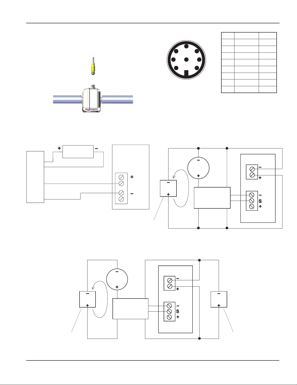
Power and signal connections are provided through the
8-pin male bulkhead connector on the meter housing
(20 ft (6 m) cable provided). See the Pin Assignment and
Connections diagrams.
Pulse Output Only with FT520
_
FT520
12
+
SEN 1
_
G
SEN 2
Pin 8
Pin 2
PE202
Pin 3
Pin 1
Red
+
White
12 Vdc
power
Brown
Green
5
4
6
3 7
8
2
Cable Plug Contact
Arrangement
1
Pin # Function Color
1 Pulse (-) White
2 Ground Brown
3 Pulse (+) Green
4 4-20 (+) Yellow
5 Not used Grey
6 Not used Pink
7 4-20 (-) Blue
8 Power (+) Red
4-20 mA Device and FT430/440 with Single Power Supply
Important: 4-20mA device input resistance must not exceed 250 Ω
4-20 mA
_
12–15
Vdc
+
loop
_
4-20 mA
device
+
7
4
Blue
PE202
2
8
1
3
Brown
White
Power
FT430/440
_
S
+
_
+
May be external
or internal to the
FT430/440
4-20 mA
_
24
Vdc
+
loop
May be external
or internal to the
FT430/440
Dual Power Supply with Loop Isolation
_
4-20 mA
device
+
7
4
Yellow
Blue
PE202
2
8
1
3
Brown
White
Red
Power
_
+
FT430/440
_
S
+
Sensor Input
Yellow
_
12–15
Vdc
+
May be external
or internal to the
FT430/440
Sensor Input
Red
Seametrics • 253.872.0284 Page 7 seametrics.com
Page 8

OPERATION
PE202 INSTRUCTIONSOPERATION AND TROUBLESHOOTING
The meter will output one pulse when powered up. The
newly-installed meter takes from a few seconds to a minute
for the signal to stabilize at startup, especially if it has been
dry. In normal operation, keep the meter lled with uid
and powered on to prevent this delay. When the meter
is mounted properly, an empty pipe detection feature will
normally detect absence of liquid in the pipe and register
The 4-20 mA signal outputs 4 mA at zero ow and 20 mA at
20 gallons/minute ow or 3 gallons per minute, depending
on model.
The pulse signal is a 50% duty cycle pulse set at:
PE202-075: 500 pulses/liter (1892 pulses/gallon)
PE202-038: 1,000 pulses/liter (3785 pulses/gallon)
zero ow.
TROUBLESHOOTING
Problem Probable Causes Things to try…
No output Reversed ow direction Reverse ow connections
Empty pipe Check piping conditions
Flow rate below minimum Select a different ow meter
Loose or incorrect wiring Check electrical connections
Fluid conductivity too low Select a different ow meter
Electrical noise Relocate meter or reduce noise
Flow rate incorrect Fluid conductivity too low Select a different ow meter
Empty pipe Check piping conditions
Electrical noise Relocate meter or reduce noise
Seametrics • 19026 72nd Avenue South • Kent, Washington 98032 • USA
(P) 253.872.0284 • (F) 253.872.0285 • 1.800.975.8153 • seametrics.com
LT-14229r2.0 20160912
9/12/16
 Loading...