

Page 1
PD10
PULSE DIVIDER
INSTRUCTIONS
P D 1 0 P U L S E D I V I D E R I N S T R U C T I O N S
Page 2
GENERAL INFORMATION & SPECIFICATIONS
Designed for use as a meter accessory, the PD10 divider is
used primarily for pacing electronic metering pumps. Any
number from one to 9999 can be set on rotary switches.
Each time the divider has received the set number of pulses
from the meter, it puts out one pulse to stroke the pump.
The PD10 is also useful in boiler and cooling tower feed
and bleed operations, and for lowering frequency output of
high frequency meters. Compatible with all Seametrics flow
meters, the PD10 creates a programmable pulse meter with
an easily adjustable pulse rate.
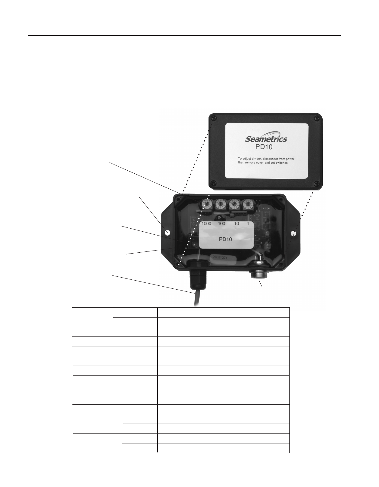
FEATURES
Protective cover
Rotary Switches (4)
Mounting Holes:
(Double-backed pressure-sensitive
tape also supplied standard)
The PD10 comes in two dif ferent housings: an enclosure
that can be mounted near the pump, and a watertight housing for mounting on the meter.
Potted for environmental
protection
Wall (Pump) housing shown
(Meter mount also available)
To leads or metering
pump connector
SPECIFICATIONS*
Page 2
Input connector for
Seametrics meter connector
Enclosure Wall (Pump) Mount
Meter Mount
Temperature
Divider Range
Setting Mechanism
Power
Maximum Sensor Load
Maximum Input Frequency
Maximum Output Frequency
Output
Output Pulse Width
Input Connection Wall Mount
Meter Mount
Output Connection Wall Mount
Meter Mount
*Specifications subject to change • Please consult our website for current data (www.seametrics.com).
Epoxy-encapsulated ABS housing with cover
Cast aluminum sealed housing
0˚ to 130˚ F (-18˚ to 55˚ C)
1 to 9999
Rotary switches
7 - 30 Vdc @ 4 mA
20 mA
350 Hz (pulses/second)
8 Hz (pulses/second)
Solid state relay; 0-250 V, 170 mA max AC/DC
0.1 second
Seametrics connector
Terminal
Pump connector on 24 inch lead
Comes with 18 foot lead
Page 3

PD10 PULSE DIVIDER
To adjust divider, disconnect from power
then remove cover and set switches
INSTALLATION & CONNECTIONS
SENSOR
POWER
S
+
-
+
-
0
1
2
3
4
5
6
7
8
9
0
1
2
3
4
5
6
7
8
9
0
1
2
3
4
5
6
7
8
9
0
1
2
3
4
5
6
7
8
9
OUTPUT
+
-
PD10M
www.seametrics.com
Flow Sensor
Red
White
Black
Electronic
Metering
Pump
7 - 30 Vdc
Power Supply
+
-
MOUNTING
The PD10M is factory-mounted on the flow sensor. The
PD10W is mounted by attaching it to the metering pump
with the included double-backed, pressure-sensitive tape.
Alternatively, the control can be wall mounted with screws
using the mounting brackets that extend out either side.
PD10M meter mounted version
POWER SOURCE
Power for the PD10 can be supplied by the metering pump
if the pump has a sensor power supply. This is the case
with LMI externally-paced metering pumps. Some pumps
require an external power supply, available from Seametrics. LMI and Seametrics connectors are available.
CAUTION:
Power supplies 18 Vdc and higher must be regulated to
prevent damage to the PD10 from voltages exceeding it's
30 V allowable maximum supply voltage caused by AC line
variations and light loading.
CONNECTIONS
The PD10M can be connected as shown.
PD10M
PD10W/LMI PUMP
The 24" pigtail that extends from the PD10W connects to an
LMI metering pump and is connected as shown.
The input connector on the control mates with any three-pin
Seametrics connector. (Meters or flow sensors to be used with
a PD10W should be ordered with Seametrics connectors.)
PD10W/LMI Pump
LMI Pump
LMI Connector
(supplied with
PD10W)
1
4
2
3
1
5
4
Sockets
-06 Option -106 Option
1. Auxiliary Power Source
2. Pulse Input
3. Ground
4. No Connection
Meter
2
3
Sockets
1. Remote On
2. Ground
3. Pulse Input
4. Aux. Power Source
5. Not Used
Sockets
1. Ground
2. Input Signal
3. Sensor Power
+7-30 Vdc*
PD10W
Seametrics
Sensor
Connector
(order with
flow meter)
3
1
2
*CAUTION: If power is supplied to the flow sensor from
the PD10, ensure that the voltage supplied to the sensor
does not exceed the sensor's allowable maximum input
voltage.
PD10W/NON-LMI PUMP
If a metering pump is used that requires a connection other
than the LMI connector supplied, cut the LMI connector off.
Connect the PD10W to the pump using the diagram below in
conjunction with the wiring diagram in the pump manual.
PD10W/Non-LMI Pump
POWER
PD10
The input connector on the control mates with any three-pin
Seametrics connector. (Meters or flow sensors to be used
with a PD10W should be ordered with Seametrics connectors.)
OUTPUT
+
–
+
–
Red
Black
Green
White
7-30 Vdc
Ground
Signal +
Common
Page 3
Page 4

0
1
2
3
4
5
6
7
8
9
0
1
2
3
4
5
6
7
8
9
0
1
2
3
4
5
6
7
8
9
0
1
2
3
4
5
6
7
8
9
SETTING
0
1
2
3
4
5
6
7
8
9
0
1
2
3
4
5
6
7
8
9
0
1
2
3
4
5
6
7
8
9
0
1
2
3
4
5
6
7
8
9
8
(Set Leading Switches To Zero)
The four numbered rotary switches marked "1000", "100",
"10", and "1" control the ratio of meter pulses to pump
strokes. Before setting the switches, disconnect power
to the unit by removing the connector from the pump or
unplugging the power adapter.
To set any four-digit number, rotate the dials to the appropriate numbers. For example, to set 1521, set the four switches
to "1", "5", "2", and "1". Any unused switches should be
set to zero. For example, to set 8, position the dials to "0",
"0", "0", "8". See samples below.
Setting Examples
TROUBLESHOOTING
Problem
Metering pump not stroking Meter dials not turning Check visually, then check for
adequate flow
Probable Cause
Try...
Meter pickup not working Remove from meter, check with a
magnet
Pump connector not plugged in all the way Check or tighten threaded locking
ring (LMI)
Pump doesn’t supply power to the PD10 Check pump manual, add power
supply
PD10 set to large number or all zeroes Check rotary switches, esp. for
leading zeroes
Pump strokes continually Pump not set for external pacing Check pump manual and selector
switch
Pump doesn’t stroke often enough PD10 set for wrong number Review setting on this page, check
or too often rotary switches
Multiple contacts from meter Set PD10 to 1 contact/pump stroke
(0001) and see if the pump strokes
once for each magnet revolution
Meter ordered with wrong pulse rate Check meter model/serial tag
Page 4
Seame t r i c s I ncorpo r a t e d • 1902 6 7 2 n d Avenu e S o u t h • Ke n t , W a s hingto n 9 8 0 3 2 • US A
(P) 2 5 3 . 8 7 2 . 0284 • ( F ) 2 53.872 . 0 2 8 5 • 1.80 0 . 9 7 5 . 8153 • w w w . s e ametri c s . c o m
LT-65200031-E
1/4/10
 Loading...