

MJ-SERIES
ISO
PULSE METER INSTRUCTIONS
MJ-SERIES PULSE METER INSTRUCTIONS
9001:2008
CERTIFIED COMPANY
GENERAL INFORMATION, INSTALLATION and MAINTENANCE
GENERAL INFORMATION
MJ-Series meters use the internationally-accepted multi-jet
principle. A gear train drives the register totalizer dials. For
pulse output, one of the pointers is replaced by a magnet
arm, which is detected by an encapsulated sensor attached
to the outside of the lens.
MJE (cold water) and MJHE (hot water) meters use a solidstate, long-lasting Hall-effect sensor, which requires power.
They are suited for use with Seametrics controls and metering
pumps (LMI for instance) that have sensor power.
MJR (cold water) and MJHR (hot water) meters use a reed
switch. They provide a dry contact closure and do not require
power.
MJT (cold water) and MJHT (hot water) meters do not have a
sensor, and they totalize only.
INSTALLATION
SPECIFICATIONS*
Power
Temperature
Cold Water
Pressure
Materials Body
Internals
Magnet
Accuracy
Pulse Output
Sensor
Max Current
Cable Length
Flow Rates (GPM)
Minimum
**Maximum
*Specications subject to change • Please consult our website for current
data (www.seametrics.com).
**CAUTION: Excessive ow can cause breakage.
Do not exceed recommended maximums.
Hot Water
Max Voltage
6 mA at 12 Vdc (MJE/MJHE only)
105˚ F (40˚ C) max
194˚ F (90˚ C) max
150 psi operating
Cast bronze, epoxy powder coated inside and out
Engineered thermoplastic
Alnico
+/- 1.5% of reading
MJE/MJHE MJR/MJHR MJT/MJHT
Hall-effect Reed switch Totalizer only
20 mA 20 mA n/a
24 Vdc 24 Vdc or Vac n/a
12’ (4 m) standard (2000’ maximum run)
3/4” 1” 1-1/2” 2”
0.22 0.44 0.88 1.98
22 52 88 132
Position. MJ-Series meters should be installed horizontally
with the register up. Vertical mounting will result in some degree of under-measurement and shortened life of the bearings.
No upstream straight pipe is required.
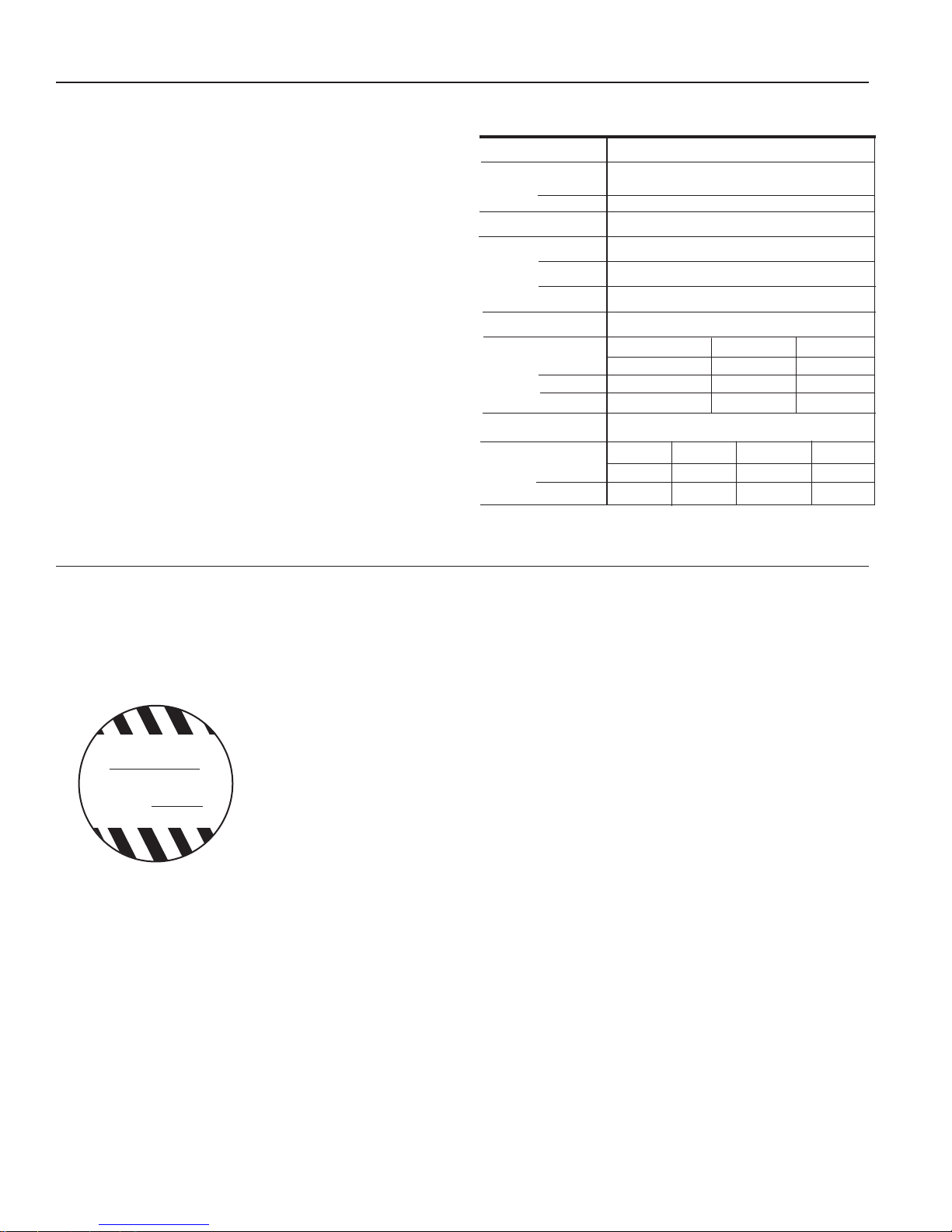
Caution: These water meters are
WARNING
DO NOT INSTALL
METER IN OVERHEAD
INDOOR PIPING OR
WHERE LEAKAGE
MAY CAUSE DAMAGE
not recommended for installation
in uninsulated suspended ceilings where freezing is possible,
or in any overhead indoor piping
conguration where leakage may
cause damage.
Couplings. Male NPT threaded couplings are included with
each meter. The threads on the end of the meter are IPS
straight threads one size bigger than the meter size. Though
it is possible to thread a standard pipe coupling directly onto
the meter for close coupling, the included couplings are much
preferable because they provide a union connection for meter
service. Be sure to use the included gasket between the end
of the meter and the coupling.
Connections. MJE/MJHE and MJR/MJHR sensors are supplied with a color coded output cable (see diagram, page 4).
Optional connectors can be ordered to plug directly into a
Seametrics control or LMI metering pump.
Pulse Output. Both MJE/MJHE and MJR/MJHR sensors
respond to a magnet that rotates on the face of the meter
under the lens. The sensor turns on and off once each time
the magnet passes under it. Sensors are designed for electronic control loads, and should not be used to switch power
loads or line voltages. See maximum current and voltage
ratings, under Specications.
MAINTENANCE
Seametrics recommends all service to be performed by an
authorized distributor or the factory to maintain the integrity
of the protective tamper-proof wire-and-seal.
Inlet Strainer. Clean the strainer yearly, or as required, depending on water condition. Pull out the strainer or backush
the meter to loosen trapped particulates.
Calibration. Meters used for billing or billing exemp-
tion may be regulated by state or local authorities. New
meters are factory-tested to meet the AWWA C-708
Multi-Jet Meter accuracy specification. Some states
require retesting at various intervals, typically eight years for
3/4" meters, six for 1", and four for 1-1/2" and 2". Meters
used for control should be tested every 5-10 years. Testing
may be done by a local mobile meter service or in a private
or municipal meter shop. Changes in calibration should be
made at an authorized meter shop.
Page 2
 Loading...