

Page 1
MJ-SERIES
ISO
PULSE METER INSTRUCTIONS
MJ-SERIES PULSE METER INSTRUCTIONS
9001:2008
CERTIFIED COMPANY
Page 2
GENERAL INFORMATION, INSTALLATION and MAINTENANCE
GENERAL INFORMATION
MJ-Series meters use the internationally-accepted multi-jet
principle. A gear train drives the register totalizer dials. For
pulse output, one of the pointers is replaced by a magnet
arm, which is detected by an encapsulated sensor attached
to the outside of the lens.
MJE (cold water) and MJHE (hot water) meters use a solidstate, long-lasting Hall-effect sensor, which requires power.
They are suited for use with Seametrics controls and metering
pumps (LMI for instance) that have sensor power.
MJR (cold water) and MJHR (hot water) meters use a reed
switch. They provide a dry contact closure and do not require
power.
MJT (cold water) and MJHT (hot water) meters do not have a
sensor, and they totalize only.
INSTALLATION
SPECIFICATIONS*
Power
Temperature
Cold Water
Pressure
Materials Body
Internals
Magnet
Accuracy
Pulse Output
Sensor
Max Current
Cable Length
Flow Rates (GPM)
Minimum
**Maximum
*Specications subject to change • Please consult our website for current
data (www.seametrics.com).
**CAUTION: Excessive ow can cause breakage.
Do not exceed recommended maximums.
Hot Water
Max Voltage
6 mA at 12 Vdc (MJE/MJHE only)
105˚ F (40˚ C) max
194˚ F (90˚ C) max
150 psi operating
Cast bronze, epoxy powder coated inside and out
Engineered thermoplastic
Alnico
+/- 1.5% of reading
MJE/MJHE MJR/MJHR MJT/MJHT
Hall-effect Reed switch Totalizer only
20 mA 20 mA n/a
24 Vdc 24 Vdc or Vac n/a
12’ (4 m) standard (2000’ maximum run)
3/4” 1” 1-1/2” 2”
0.22 0.44 0.88 1.98
22 52 88 132
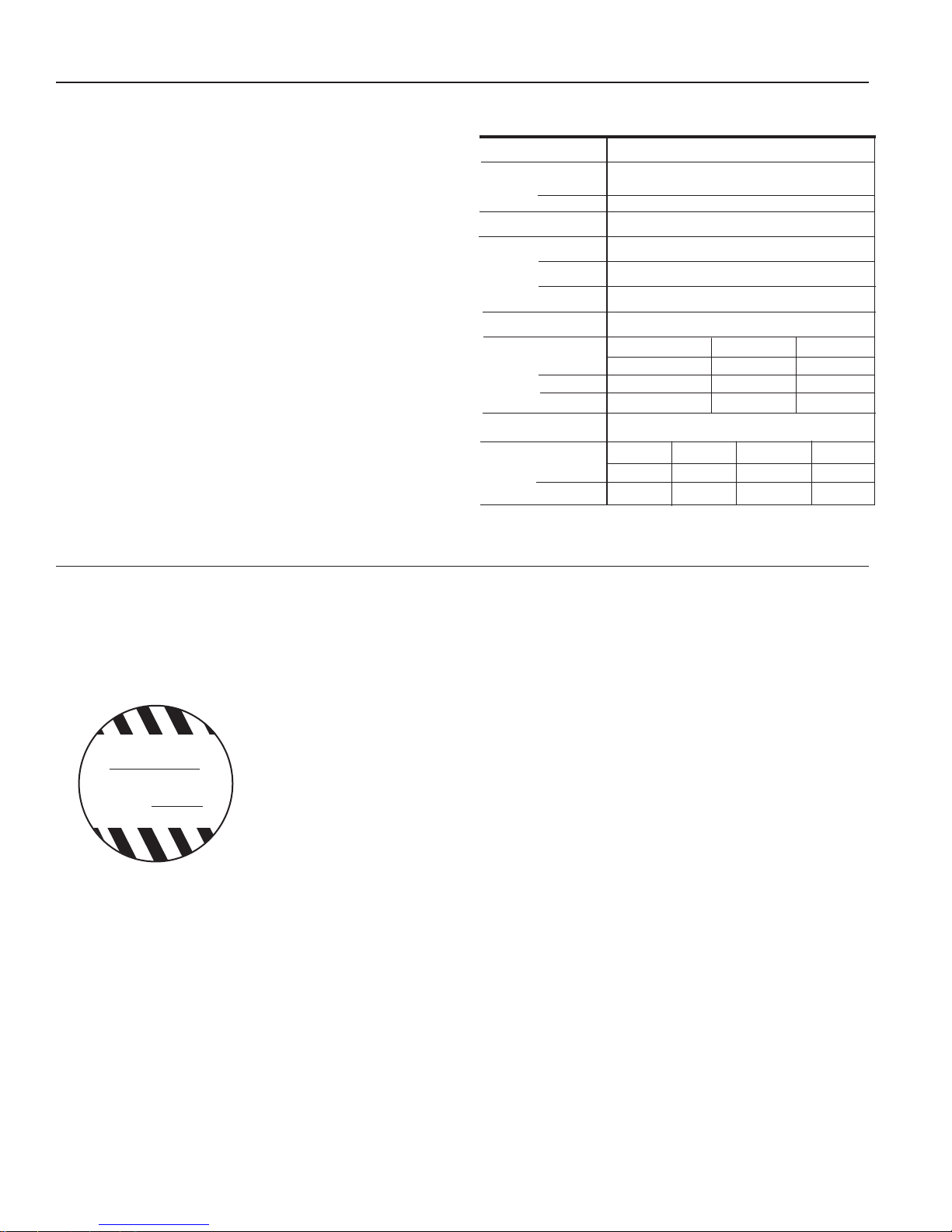
Position. MJ-Series meters should be installed horizontally
with the register up. Vertical mounting will result in some degree of under-measurement and shortened life of the bearings.
No upstream straight pipe is required.
Caution: These water meters are
WARNING
DO NOT INSTALL
METER IN OVERHEAD
INDOOR PIPING OR
WHERE LEAKAGE
MAY CAUSE DAMAGE
not recommended for installation
in uninsulated suspended ceilings where freezing is possible,
or in any overhead indoor piping
conguration where leakage may
cause damage.
Couplings. Male NPT threaded couplings are included with
each meter. The threads on the end of the meter are IPS
straight threads one size bigger than the meter size. Though
it is possible to thread a standard pipe coupling directly onto
the meter for close coupling, the included couplings are much
preferable because they provide a union connection for meter
service. Be sure to use the included gasket between the end
of the meter and the coupling.
Connections. MJE/MJHE and MJR/MJHR sensors are supplied with a color coded output cable (see diagram, page 4).
Optional connectors can be ordered to plug directly into a
Seametrics control or LMI metering pump.
Pulse Output. Both MJE/MJHE and MJR/MJHR sensors
respond to a magnet that rotates on the face of the meter
under the lens. The sensor turns on and off once each time
the magnet passes under it. Sensors are designed for electronic control loads, and should not be used to switch power
loads or line voltages. See maximum current and voltage
ratings, under Specications.
MAINTENANCE
Seametrics recommends all service to be performed by an
authorized distributor or the factory to maintain the integrity
of the protective tamper-proof wire-and-seal.
Inlet Strainer. Clean the strainer yearly, or as required, depending on water condition. Pull out the strainer or backush
the meter to loosen trapped particulates.
Calibration. Meters used for billing or billing exemp-
tion may be regulated by state or local authorities. New
meters are factory-tested to meet the AWWA C-708
Multi-Jet Meter accuracy specification. Some states
require retesting at various intervals, typically eight years for
3/4" meters, six for 1", and four for 1-1/2" and 2". Meters
used for control should be tested every 5-10 years. Testing
may be done by a local mobile meter service or in a private
or municipal meter shop. Changes in calibration should be
made at an authorized meter shop.
Page 2
Page 3

CHANGING PULSE RATES
G2
G1
12
11
12
11
G2
G1
12
11
12
11
11
G1
Setting Your Pulse Rate. The pulse rate is determined by which
sensor was ordered from the factory (single reed switch, dual
reed switch, or single Hall-effect) and by the dial on which the
magnet pointer is located. The pointer is set at the factory, but
can be changed in the eld as follows.
In the table below: 1) Locate your meter size (Column 1); 2)
Find your desired pulse rate (Column 2); 3) Note the magnet
pointer position (Column 3); 4) Move the magnet pointer to
the appropriate dial position (using the detailed instructions
below the table); 5) Use the appropriate Connection Diagram
(from Column 4) to wire the sensor to your remote device (using
diagrams on page 4).
Col. 1 Col. 2 Col. 3 Col. 4
Meter
Size
3/4"
1"
1-1/2"
2"
*These pulse rates available in MJR and MJHR dual reed switch meters only.
†This pulse rate available in MJR and MJHR single reed switch meters only.
Pulse
Rate
*20 P/
10 P/
†4 P/G
*2 P/G x0.1
1 P/G x0.1
*5 G/Px
10 G/Px
*50 G/P x10 2
100 G/P x10 1
†4 P/G
*2 P/G x0.1 2
1 P/G x0.1 1
*5 G/Px
10 G/Px
*50 G/P x10 2
100 G/P
†4 P/G x0.
*2 P/
1 P/
*5 G/Px
10 G/Px
*50 G/P x10 2
100 G/P
†4 P/
*2 P/G
1 P/G
*5 G/Px
10 G/Px
*50 G/P
100 G/P x10 1
Moving the Magnetic Pointer. Remove meter top and lens,
taking care not to lose the sealing ring. With ngers, lift the
magnet pointer off its shaft and remove the plain pointer from
the target dial. Reverse their positions and press them rmly
into place. Securely seat the sealing ring and replace the lens,
Magnet Pointer
Dial Position
x0.01
x0.01
x0.1
x0.1
x10
x0.1
x0.1
x10
x0.1
x0.1
x0.1
x10
Connection
Diagram #
1
2
1
1
1
1
2
1
2
matching the tab on the lens to the notch on the meter to align
the sensor with the magnetic pointer dial. Thread the meter top
on and tighten.
Sample Set-Up. A 1” meter is shown with the magnet
pointer set at the x10 dial, with a pulse rate of 100 Gallons per Pulse (that is, 10 increments on the x10 dial, or
10x10=100 Gal/Pulse).
1” Meter
100 Gal/Pulse
25mm
40˚C
U.S. GALLONS
X1
X0.1
X100
X10
Magnet Pointer
x10 Dial
(10 x 10=100 G/P)
[With the magnet pointer
on the x1 dial, the pulse
rate would be 10x1=10
Gal/Pulse. With the magnet pointer on the x0.1 dial,
the pulse rate would be
10x.1=1 Gal/Pulse.]
Special Congurations.
X100
20mm
U.S. GALLONS
40˚C
X0.01
X0.1
X10
X1
The 3/4” meter has a fourth dial,
as shown above. The x0.01 dial is
used for 20 P/G and 10 P/G rates.
Note: The 3/4” meter has a 5 digit
totalizer.
25mm
U.S. GALLONS
40˚C
X0.1
The 4 P/G rate requires
a special magnet, placed
on the x0.1 dial, as shown
above.
X100
X10
X1
Reading Your Meter. The Total Flow that has passed
through your meter is read by starting at the top of the reg-
ister with the Six-Digit Totalizer, and then reading clockwise
around the small dials. In the example below, the Six-Digit
Totalizer reads 13,800 (138 x 100), and the dials read 60
(6 x 10), 2 (2 x 1), and .4 (4 x .1) respectively. The Total
Flow is 13,862.4 gallons.
1” Meter
100 Gal/Pulse
Six-Digit Totalizer
(reads 138x100)
x10 Gal Dial
(reads 6x10)
x1 Gal Dial
(reads 2x1)
x0.1 Gal Dial
(reads 4x0.1)
25mm
40˚C
1 3 8
U.S. GALLONS
X1
X0.1
X100
X10
†NOTE: A special magnet (available from the factory) is required
to achieve a rate of 4 pulses per gallon. It should be placed on
the x0.1 dial, with non-magnetic pointers on the remaining dials.
Otherwise, the procedure is the same.
(NOTE: Disregard the color of the numbers on the totalizer when reading
your total.)
The “ones” digit is signicant but the fact that it is red is not signicant.
Page 3
Page 4

CONNECTIONS, MAINTENANCE and REPAIR
CONNECTION DIAGRAMS
Diagram 1: Single Sensor Diagram 2: Dual Sensor
Blue - (No Connection)
Black - Common
Red - N O
Black ( - )
White (signal)
Red (+)
MJR or MJHR:
Reed Switch
MJE or MJHE:
Hall-Effect
NOTE: The Dual Sensor is distinguished by a red stripe on the cable at the
base of the sensor.
NOTE: MJ(H)E not available with dual sensor
Black - Common
Red - N O
Blue - N O
MJR or MJHR:
Reed Switch
To Distinguish Single Sensor From Dual:
Single: (if new from factory) blue wire is cut back on cable end.
Dual: A red stripe will be on cable near sensor.
INTERNAL PARTS REPLACEMENT. All of the internal parts of
an MJ-Series meter lift out as a unit, after the top has been
unscrewed. The lens can then be removed and the internal as-
MJ-SERIES PARTS
COLD WATER MODELS ONLY
1 Lid and Hinge Pin Assembly 101068 101069
2 Lens Gasket Assembly 101071 101072
a Internal Assembly (gallons) 101073 101074
3
b Internal Assembly (cubic feet) 101077 101078
4 Coupling Assembly (incl 2 sets) 101017 101018
5 Coupling Gasket Assembly (incl 2) 101081 101082
6 Lens 101004 101004
7 Sensor Screw 101045 101045
a Single Reed Switch Sensor (MJR) 100980 100980
8
b Double Reed Switch Sensor (MJR) 100993 100993
c Single Hall-Effect Sensor (MJE) 101065 101065
a Register (gallons) 100997 100998
9
b Register (cubic feet) 101006 101007
10 Internal Strainer 101016 101043
11 Tubular Strainer 101029 101030
12 Register Gasket 101013 101027
COLD WATER MODELS ONLY
1 Lid and Hinge Pin Assembly 101070 101070
2 Lens Gasket Assembly 101085 101085
a Internal Assembly (gallons) 101075 101076
3
b Internal Assembly (cubic feet) 101079 101081
4 Coupling Assembly (incl 2 sets) 101019 101020
5 Coupling Gasket Assembly (incl 2) 101083 101084
6 Lens 101004 101004
7 Sensor Screw 101045 101045
a Single Reed Switch Sensor (MJR) 100980 100980
8
b Double Reed Switch Sensor (MJR) 100993 100993
c Single Hall-Effect Sensor (MJE) 101065 101065
a Register (gallons) 100999 101000
9
b Register (cubic feet) 101008 101009
10 Internal Strainer 101044 101044
11 Tubular Strainer 101031 101032
12 Register Gasket 102228 102228
¾” 1”
1½” 2”
1
2
3a
or
3b
Note: Dual sensor can be used as a single sensor also - use either the red OR
the blue wire w/black. If using it as a dual sensor then connecting red and blue
together will produce two pulses with every revolution of magnet.
sembly lifted out. If necessary, turn the meter upside down and
tap one end lightly on a countertop to loosen the internals. The
assembly can be separated by hand.
HOT WATER MODELS ONLY
1 Lid and Hinge Pin Assembly 101354 101355
2 Lens Gasket Assembly 101332 101333
a Internal Assembly (gallons) 101350 101351
3
b Internal Assembly (cubic feet) 101346 101347
4 Coupling Assembly (incl 2 sets) 101017 101018
5 Coupling Gasket Assembly (incl 2) 101081 101082
6 Lens 101004 101004
7 Sensor Screw 101045 101045
a Single Reed Switch Sensor (MJR) 100980 100980
8
b Double Reed Switch Sensor (MJR) 100993 100993
6
7
8 a-c
9a
or
9b
12
10
11
5
4
c Single Hall-Effect Sensor (MJE) 101065 101365
a Register (gallons) 101372 101373
9
b Register (cubic feet) 101368 101369
10 Internal Strainer 101379 101380
11 Tubular Strainer 101382 101383
12 Register Gasket 101339 101340
HOT WATER MODELS ONLY
1 Lid and Hinge Pin Assembly 101356 101356
2 Lens Gasket Assembly 101334 101334
a Internal Assembly (gallons) 101352 101353
3
b Internal Assembly (cubic feet) 101348 101349
4 Coupling Assembly (incl 2 sets) 101019 101020
5 Coupling Gasket Assembly (incl 2) 101083 101084
6 Lens 101004 101004
7 Sensor Screw 101045 101045
a Single Reed Switch Sensor (MJR) 100980 100980
8
b Double Reed Switch Sensor (MJR) 100993 100993
c Single Hall-Effect Sensor (MJE) 101065 101065
a Register (gallons) 101374 101375
9
b Register (cubic feet) 101370 101371
10 Internal Strainer 101381 101381
11 Tubular Strainer 101384 101385
12 Register Gasket 101341 101341
¾” 1”
1½”
2”
Page 4
(P) 253.872.0284 • (F) 253.872.0285 • 1.800.975.8153 • www.seametrics.com
Seametrics Incorporated • 19026 72nd Avenue South • Kent, Washington 98032 • USA
LT-65200120r1.1-20160226
2/26/16
 Loading...