

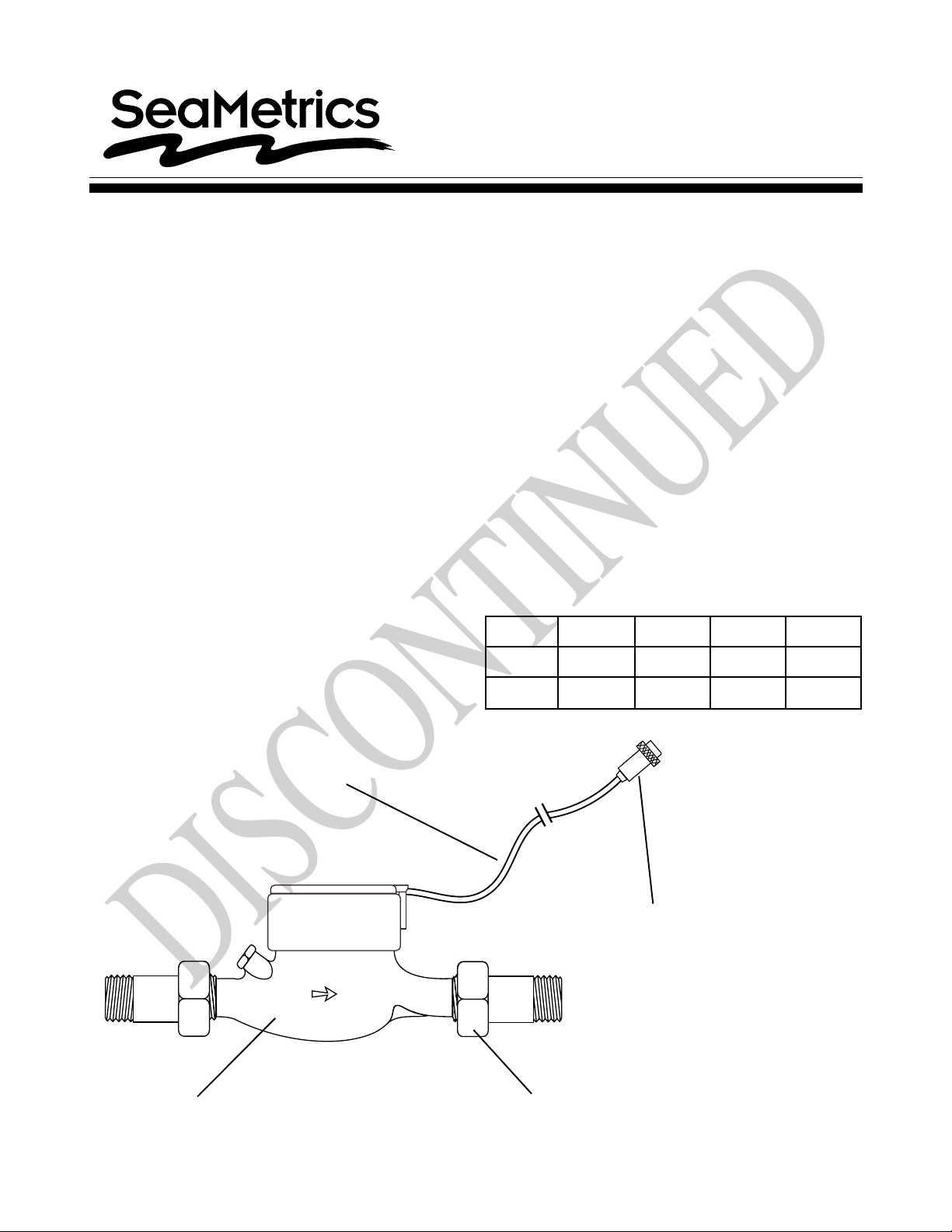
MD-Series Pulse Meter
DISCONTINUED
Instructions
General Information
MD-Series meters use the multi-jet principle, which has
been an internationally-accepted standard for many
years. This type of meter is known for its wide range,
simplicity, and accuracy in low-quality water. The
impeller is centered in a ring of jets, with inlet jets on
one level and outlet jets on another. A gear train drives
the register totalizer dials. For pulse output, one of the
dials is replaced by a gear, which turns a magnet that
is detected by an encapsulated sensor threaded into
the outside of the lens. Pulse rate is determined by the
gear and the dial on which the gear is placed.
Mechanically , all MD-Series meters are the same. The
difference between MDE and MDR meters is in the sensor. MDE meters use a solid-state, long-lasting Halleffect sensor, which requires power. They are suited
for use with SeaMetrics controls and metering pumps
(LMI for instance) which have sensor power. MDR
meters use a two-wire reed switch. They provide a dry
contact closure and do not require power. MDT meters
do not have a sensor, totalize only.
Specifications
Materials
Case Cast bronze
Internals Engineered thermoplastic
Magnet Ceramic permanent
Temperature 105° F, 40° C
Max. Pressure 150 PSI operating
Accuracy 1-1/2% of reading
Sensor
MDE Solid state
MDR Reed switch
Max. Current
MDE 20 mA
MDR 50 mA
Max. Voltage
MDE 24 VDC
MDR 24 VDC or 24 VAC
Sensor Power (MDE) Minimum 6 mA at 12 VDC
Cable Length 18 ft. standard, 2,000 ft. max.
Flow Rates (GPM):
3/4" 1" 1-1/2" 2"
Minimum 0.22 0.44 0.88 1.98
Features
Cast bronze body-
Either MDE or MDR sensor
threads into lens without
removing top
meets AWW A
specifications
Maximum 22 52 88 132
Connector for metering pump or
SeaMetrics control - optional
Union end couplings
for easy service
Page 1 of 4

Installation
DISCONTINUED
WARNING
DO NOT INSTALL
meter in overhead
Indoor piping or where
leakage
may cause damage
Position. MD-Series meters should be installed horizontally with the register up. Vertical mounting will result
in some degree of under-measurement and shortened
life of the bearings.
Couplings. Couplings are included with each meter.
These provide male NPT threads the same nominal size
as the meter. The threads on the end of the meter are
IPS straight threads one size bigger than the meter size.
It is possible to thread a standard pipe coupling directly
onto the meter for close coupling, but the meter couplings are much preferable because they provide a union
connection for meter service. Be sure to use the included
gasket between the end of the meter and the coupling.
Inlet Conditions. No upstream straight pipe is required.
A strainer is built in to protect from solids, and should be
periodically cleaned.
Air Bleed. When the meter is first installed, trapped air
should be removed. To do this, loosen the meter couplings slightly and rotate the meter to an inverted
position. Allow water to flow, then rotate the meter
back to an upright position and tighten.
Connections. MDE and MDR sensors are supplied with
a color coded output cable. See the diagram for color
codes and polarity . Optional connectors can be ordered
to plug directly into a SeaMetrics control or a specific
brand of metering pump.
sensor connection
MDE
MDRsensor connection
These water meters are not
recommended for installation
indoors or anywhere leakage
may cause damage.
(BLACK) Power (-)
(WHITE) Signal
(RED) Power (+) 6-24 VDC
(BROWN) Common
(WHITE) N.O.
Pulse Output. Both MDE and MDR sensors respond to
a magnet which rotates on the face of the meter under
the lens. The sensor turns on and off once each time
the magnet passes under it. Sensors are designed for
electronic control loads, and should not be used to switch
power loads or line voltages. See maximum current and
voltage ratings, under Specifications.
Maintenance
SeaMetrics recommends all service to be performed by
authorized distributor or factory to maintain the integrity
of the protective tamper-proof wire-and-seal.
Inlet Strainer. Clean the strainer yearly, or as required,
depending on water condition. Pull out the strainer or
backflush the meter to loosen trapped particulates.
Calibration. Meters used for billing or billing exemption
may be regulated by state or local authorities. New
meters are factory-tested to meet the A WWA C-708 MultiJet Meter accuracy specification. Some states
require retesting at various intervals, typically eight years
for 3/4" meters, six for 1", and four for 1-1/2" and 2".
Meters used for control should be tested every 5-10
years. Testing can be done by local meter shops authorized for this purpose, or can be done by the factory.
Please contact SeaMetrics before sending meter in for
calibration or servicing.
Internal Parts Replacement. All of the internal parts of
an MD-Series meter lift out as a unit, after the top has
been unscrewed. The lens can then be removed and the
internal assembly lifted out. The three pieces of the
assembly can be separated by hand.
Excessive flow can cause breakage. Compare maximum
flow with the flow rating table.
Changing Pulse Rates. After removing the meter top,
lift off the center magnet to expose the gears. If the only
change required is moving the drive gear (for example
from one gallon/pulse to ten gallons/pulse), gently pull
the drive gear off its shaft. Remove the pointer on the
target shaft and push the drive gear onto the target shaft
as far as it will go. Put the pointer on the vacant shaft
and push on.
If a different gear set is required, follow the same procedure, replacing rather than moving the drive gear. To
install a drive gear on another shaft, remove the pointer
and then press the gear down until it bottoms. Use the
pulse rate chart to determine the position.
2 of 4

3/4" - 10 gallons/pulse
DISCONTINUED
Standard
(X1) gearset
3/4"
1"
1-1/2"
2"
Pulse
Rate
20 P/G
10 P/G 1
2 P/G X0.1 2
1 P/G X0.1 1
5 G/P X1 2
10 G/P X1 1
50 G/P X10 2
100 G/P X10 1
20 P/G
10 P/G
2 P/G X0.1 2
1 P/G X0.1 1
5 G/P X1 2
10 G/P X1 1
50 G/P X10 2
100 G/P X10 1
2 P/G 2
1 P/G 1
5 G/P X1 2
10 G/P X1 1
50 G/P X10 2
100 G/P X10 1
500 G/P X100 2
1000 G/P X100 1
2 P/G 2
1 P/G 1
5 G/P X1 2
10 G/P X1 1
50 G/P X10 2
100 G/P X10 1
500 G/P X100 2
1000 G/P X100 1
* Unlabeled position
Drive Gear
Position
*
*
*
*
*
*
*
*
Gear Set
(X...)
2
move
gear to
match
2
1
X1 Drive gear
on position
3/4" - 50 gallons/pulse
X2
gearset
X10
Drive
gear on
position
3/4" - 1 gallon/pulse
X2 gearset
*Unlabelled position
X0.1 Drive
gear on
position
3 of 4

MD-Series Parts
DISCONTINUED
reed switch
w/cable
cap screw
(over)
calibration plug
(under)
strainer
slip ring
pair
lens
register
assembly
O-ring
multi-jet
assembly
Part # FOR ALL SIZES
30387 Gear Assembly , x1
30342 Gear Assembly , x2
30290 Hinge Pin
30293 Lens, Glass
30289 Lid
30296 O-ring
30300 Pickup, Reed Switch, 12' Cable
30346 Pickup, Solid State, 12' cable, MDE
30292 Slip Ring (pair)
Part # FOR 3/4" MD METERS
16125 Calibration Plug
16105 Calibration Plug Cap Screw
30381 Coupling Assembly (2 required)
30416 Coupling Gasket (2 required)
30311 Multi-jet Assembly
30308 Register Assembly
30479 Strainer
Part # FOR 1" MD METERS
16125 Calibration Plug
16105 Calibration Plug Cap Screw
30382 Coupling Assembly (2 required)
30417 Coupling Gasket (2 required)
30297 Drive Magnet
30323 Multi-jet Assembly
30321 Register Assembly
30480 Strainer
Part # FOR 1-1/2" MD METERS
30303 Calibration Plug
30305 Calibration Plug Cap Screw
30383 Coupling Assembly (2 required)
30418 Coupling Gasket (2 required)
30297 Drive Magnet
30304 Gasket
30332 Multi-jet Assembly
30330 Register Assembly
30481 Strainer
Part # FOR 2" MD METERS
30303 Calibration Plug
30305 Calibration Plug Cap Screw
30384 Coupling Assembly (2 required)
30419 Coupling Gasket (2 required)
30297 Drive Magnet
30304 Gasket
30326 Multi-jet Assembly
30328 Register Assembly
16240 Strainer
19026 72nd Ave. S., Kent, WA 98032 USA
Phone: 253-872-0284 Fax: 253-872-0285
4 of 4
www.seametrics.com 1-800-975-8153
LT-11857-B
Rev. 8-04
 Loading...