

Page 1

d
C
IP100/200 Series
Adjustable Depth Insertion
Paddlewheel Instructions
IP11x/21x
(Shown with externally
powered electronics)
IP15x/25x
(Shown with battery
powered electronics)
o
m
e
i
p
f
PROUDLY
MADE
IN THE
USA
i
t
r
e
C
ISO
9001:2008
a
n
y
Page 2

TABLE OF CONTENTS
General Information
General Information ...................................................................................................................................................Page 3
Features ...........................................................................................................................................................................Page 3
Specications ................................................................................................................................................................Page 5
Installation
Positioning the Meter ................................................................................................................................................Page 5
Immersion .......................................................................................................................................................................Page 5
IP11x/21x Installation .................................................................................................................................................Page 6
IP15x/25x Installation .................................................................................................................................................Page 6
Depth Setting ................................................................................................................................................................Page 7
Pipe Wall Thickness .....................................................................................................................................................Page 8
Flow Range .....................................................................................................................................................................Page 8
Straight Pipe Recommendations ...........................................................................................................................Page 9
Full Pipe Recommendations ....................................................................................................................................Page 10
Connections
Overview .........................................................................................................................................................................Page 11
FT430 ................................................................................................................................................................................Page 11
FT440 ................................................................................................................................................................................Page 12
FT450 ................................................................................................................................................................................Page 12
Operation and Maintenance
Operation Theory ........................................................................................................................................................Page 13
Flow Rate ........................................................................................................................................................................Page 13
Calibration (K-Factor) .................................................................................................................................................Page 13
Rotor Replacement .....................................................................................................................................................Page 13
Checking Signal ............................................................................................................................................................Page 13
Parts Explosion .............................................................................................................................................................Page 14
Parts List ..........................................................................................................................................................................Page 14
IP100/200 SERIES INSTRUCTIONS
Troubleshooting
Problem ...........................................................................................................................................................................Page 15
Probable Cause .............................................................................................................................................................Page 15
Things To Try..................................................................................................................................................................Page 15
Warranty
Seametrics Limited Warranty ..................................................................................................................................Back
Seametrics • 253.872.0284 Page 2 seametrics.com
Page 3
GENERAL INFORMATION
IP100/200 SERIES INSTRUCTIONS
The IP100/200-Series are adjustable depth insertion
paddlewheels that come in brass, PVC, or 316 stainless
models to t 3” to 40” pipe. Adapters mate with standard
1-1/2” (11x/21x) or 2” (15x/25x), or PVC (11x/21x) NPT
threaded ttings such as saddles and weldolets which may
be purchased either locally or from Seametrics.
Ruby bearings and a non-drag Hall-effect sensor give these
meters the widest ow range of any of the paddlewheel
types. A sensor detects the passage of miniature magnets
in the six rotor blades. The resulting square-wave signal
can be sent for hundreds of feet over unshielded cable
without a transmitter and connected directly to many PLC’s
and other controls without any additional electronics.
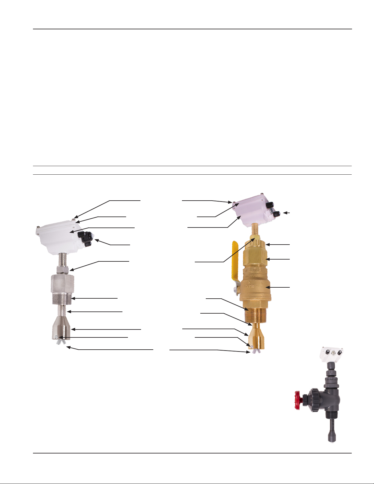
Features
Housing Screw
(connect one to ground)
Optional Electronics Module
A modular system of electronics can be installed directly
on the ow sensor or mounted remotely. The FT430
(externally powered with pulse), FT440 (loop powered),
and FT450 (battery powered) all provide digital rate and
total displays, as well as a programmable pulse; the FT440
also provides a 4-20 mA analog output. The AO55 is a
blind analog (4-20 mA) transmitter. Programmable pulse
for pump pacing is available with the PD10 (available as
wall mounted unit only).
The “hot-tap” models (IP15x/25x) can be installed or
serviced without shutting down the line by means of a
2” full-port isolation valve that comes with a nipple for
installation on the pipe tting. In most circumstances, no
special tool is required.
Cable Gland Strain Relief
IP11x/21x
(Shown with optional externally
powered electronics)
Powder-Coated Cast
Aluminum Housing
Cable Gland Strain Relief
Compression Nut for easy
adjustment, secure locking
Adapter mates with threaded tting
FNPT 1 1/2” FNPT 2”
3/4” tubing, low insertion force
(Typically no tool required)
Rotor Housing
Removable Jewel Bearings
Rotor
Locking Collar
2” Adapter (removes to
mount hot-tap machine)
Valve Assembly for hot-
tap installation
IP15x/25x
(Shown with optional
battery powered
electronics)
Hot-tap valve on
PVC version
Seametrics • 253.872.0284 Page 3 seametrics.com
Page 4
GENERAL INFORMATION
IP100/200 SERIES INSTRUCTIONS
Specications*
Pipe Size 3” to 40”
Power Low Power: 6-36 Vdc/< 2 mA Micropowered (-04 Option): 3.1-16 Vdc/60 μA @ 3.6 Vdc
Sensor Low Power: Digital Magnetoresistive Micropowered (-04 Option): Giant Magnetoresistance (GMR)
Materials Housing Powder-coated cast aluminum
Tubing/Fitting/Sensor Housing Brass, PVC, or 316 Stainless Steel
Rotor PVDF (Kynar®)
Shaft Kynar® /Tungsten Carbide (Kynar® /Ceramic or Kynar®/Silicon Carbide optional)
Bearings Ruby jewel
O-Ring (15x/25x only) EDPM
Valve Assembly for: IP11x/21x (Brass/SS) IP11x/21x (PVC) IP15x/25x (Brass/SS) IP15x/25x (PVC)
None None Bronze (316SS optional) Uses gate valve
Fitting Size Required 1.5” FNPT 2” FNPT 2” FNPT 2” FNPT
Maximum Pressure Brass/SS: 200 psi (14 bar) PVC: 150 psi (10 bar)
Temperature Brass/SS: 200˚ F (93˚ C) PVC: 130˚ F (55˚ C)
Flow Velocity 0.3 to 30 ft/sec (0.9 to 9.14 m/sec)
Accuracy ± 1.5% of full scale
Output Transistor Maximum Current Sinking 150mA (low power version only)
Cable #22 AWG 3-con, 18’ (6m); 2,000’ (610m) maximum cable run Note: 50’ (15m) maximum for battery powered
Environmental
Regulatory
*Specications subject to change. Please consult our website for the most current data (www.seametrics.com).
Kynar is a registered trademark of Arkema, Inc.
or micropowered versions.
See meter mounted electronic specication for rating.
Mark
Seametrics • 253.872.0284 Page 4 seametrics.com
Page 5
INSTALLATION
IP100/200 SERIES INSTRUCTIONS
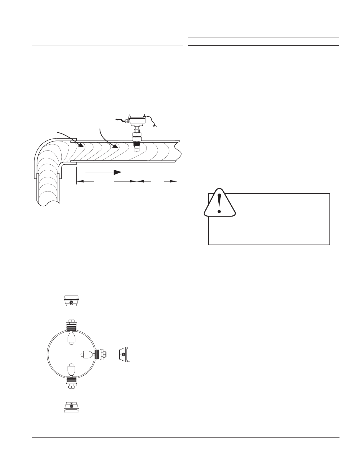
Positioning the Meter
For best results, the IP sensor should be installed with
at least ten diameters of straight pipe upstream and
ve downstream. Certain extreme situations such as
partially-opened valves are particularly difcult and may
require fteen diameters upstream. (See Straight Pipe
Recommendations.)
Faster Flow
Causes Meter
Distorted
Flow Prole
To Read High
FLOW
10X
5X
Distorted Flows
Horizontal (3 o’clock or 9 o’clock position) is the preferred
installation orientation, since it improves low-ow
performance and avoids problems with trapped air and
sediment. (See Orienting the Meter diagram below.)
Bottom (6 o’clock), top (12 o’clock), and vertical pipe
installations are all acceptable if required by the piping
layout.
Immersion
The IP100/200 Series standard sensors are not designed
for continuous underwater operation. If this is a possibility,
as in a ooded vault, a unit modied for immersion should
be specied (Option -40).
Caution: These ow sensors are
not recommended for installation
downstream of a boiler feedwater
pump where installation fault may
expose the ow sensor to boiler pressure
and temperature. Maximum recommended
temperature is 200°F.
Fair
Unacceptable if pipe
contains air
Best
Position
Fair
Unacceptable if pipe
contains sediment
Orienting the Meter
Seametrics • 253.872.0284 Page 5 seametrics.com
Page 6

INSTALLATION
IP11x/21x Installation
Fitting Installation. IP11x/21x brass/SS adapters mate with a
1-1/2” female NPT pipe thread adapter tting (2" for PVC). Any
tting that provides the matching NPT female thread may be used.
Installation procedure compensates for tting height differences.
Cut a minimum 1-3/4” hole in the pipe. If possible, measure the wall
thickness and write it down for use in depth setting. Then install the
threaded tting (saddle, weldolet, etc.) on the pipe.
Meter Installation. Loosen the compression nut so that the adapter
slides freely. Pull the meter fully upward and nger-tighten the
compression nut. Using a thread sealant, install the adapter in the
pipe tting. Do not overtighten. Now loosen the compression
nut, lower the meter to the appropriate depth setting (see diagram
and instructions that follow). Caution: Do not allow the meter to
fall into the pipe uncontrolled, as this may damage the meter.
Be sure ow is in the direction of the arrow on the housing. Fully
tighten compression nut.
IP15x/25x Installation
IP100/200 SERIES INSTRUCTIONS
Compression nut
Adapter mates with
FNPT threads
Hot tap’ IP meters are designed to be installed and serviced without
depressurizing the pipe.
Fitting Installation. The IP15x and 25x adapters mate with a 2”
FNPT threaded tting for compatibility with the 2” isolation valve.
Any tting that provides matching NPT female thread may be used.
The installation procedure compensates for differences in tting
height.
If initial installation is performed on an unpressurized pipe, cut a
minimum 1-3/4” hole in the pipe. If possible, measure the wall
thickness and write it down for use in depth setting. Then install the
threaded tting (saddle, weldolet, etc.) on the pipe.
If it is necessary to do the initial installation under pressure, any
standard hot tap drilling machine with 2” NPT adapter, such as a
Transmate or a Mueller, can be used. Ordinarily, it is not necessary
to use an installation tool, since the small-diameter tube can be
controlled by hand at all but the highest pressures.
Meter Installation. Remove the sensor unit from the valve assembly.
Using a thread sealant, install the valve assembly on the pipe tting.
If the initial installation is a pressure (“hot”) tap, remove the 1-1/2”
x 2” adapter bushing at the back of the valve. Thread the tapping
machine on, open the valve, and tap using a minimum of 1-3/4” or
maximum 1-7/8” cutter. After retracting the machine and closing
the valve, reinstall the ow sensor. When the sensor is secure, open
the valve and adjust depth setting (see diagram and instructions that
follow). Be sure ow is in the direction of the arrow on the housing.
Tighten locking collar and compression nut fully.
Compression nut
Locking collar
2” adapter removes
to mount hot-tap
machine
Full-port 2” ball
valve allows sensor
removal
Mates with 2”
FNPT threads
IP15x/25x Sensor
Removal
Seametrics • 253.872.0284 Page 6 seametrics.com
Page 7
INSTALLATION
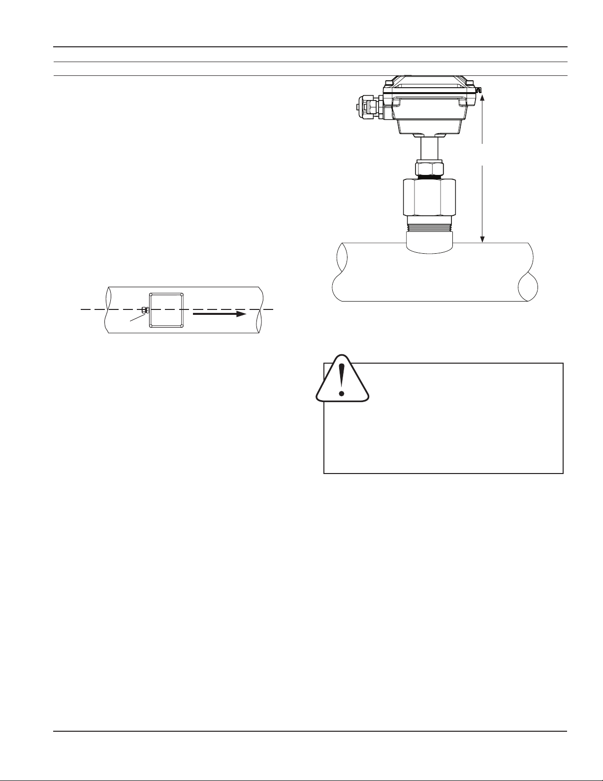
Depth Setting
It is important for accuracy that the sensor be inserted to
the correct depth into the pipe.
IP100/200 SERIES INSTRUCTIONS
1. Go to www.seametrics.com and select the K-factor
Calculator located at the bottom of the home page
to nd dimension D (insertion depth setting)*.
2. Measuring from the outside of the pipe to the joint
in the housing, as shown in the diagram, adjust
the sensor to Dimension D and hand-tighten
compression nut.
3. Align the conduit housing with the centerline of the
pipe, as shown. Be sure the arrow on the housing
points in the direction of ow.
strain
relief
FLOW
4. Check Dimension D one more time.
5. Fully tighten the compression nut.
Record your settings. Once you have the meter set up and
operational, it is important to record you meter settings
and save them future reference.
“D”
Proper Depth Setting
Caution! Never attempt to remove a
ow sensor when there is pressure in the
pipe unless it is specically designed for
hot tap installation and removal. Loosen
the compression nut slowly to release any trapped
pressure. If uid sprays out when removing the
sensor, stop turning and depressurize the pipe. Failure
to do so could result in the sensor being thrown from
the pipe, resulting in damage or serious injury.
K-Factor ______________________________________
Insertion Depth (Dim. D) _____________________
* For pipe sizes larger than 50”, please consult factory.
Seametrics • 253.872.0284 Page 7 seametrics.com
Page 8

INSTALLATION
IP100/200 SERIES INSTRUCTIONS
Table 1: Pipe Wall Thickness (inches)
Nominal Pipe Size*
3" 4" 6" 8" 10" 12" 14" 16" 18" 20" 24" 30" 36"
Schedule 40 0.216 0.237 0.280 0.322 0.365 0.406 0.438 0.500 0.562 0.593 0.687 -- --
Schedule 80 0.300 0.337 0.432 0.500 0.593 0.687 0.750 0.843 0.937 1.031 1.218 -- --
Stainless Steel
(10S)
Stainless Steel
(40S)
Copper Tubing
(Type L)
Copper Tubing
(Type K)
Brass Pipe 0.219 0.250 0.250 0.312 0.365 0.375 -- -- -- -- -- -- --
Duct. Iron
(Class 52)
0.120 0.120 0.134 0.148 0.165 0.180 0.188 0.188 0.188 0.218 0.250 0.312 0.312
0.216 0.237 0.280 0.322 0.365 0.375 0.375 0.375 0.375 0.375 0.375 0.375 0.375
0.090 0.100 0.140 0.200 0.250 0.280 -- -- -- -- -- -- --
0.109 0.134 0.192 0.271 0.338 0.405 -- -- -- -- -- -- --
0.280 0.290 0.310 0.330 0.350 0.370 0.390 0.400 0.410 0.420 0.440 0.470 0.530
* Call factory for larger pipe sizes.
Table 2: Flow Range in Sched. 40 pipe (in GPM)
Nominal Pipe Size*
Velocity
(ft/sec)
0.3 6.9 11.9 18.7 27 46.8 73.7 105 165 376 874 1060 1690
0.5 11.5 19.8 31.2 45 78 123 174 275 627 1460 1770 2820
1.0 23 39.7 62.4 90 156 246 349 551 1250 2910 3530 5640
2.0 46.1 79.4 125 180 312 492 698 1100 2510 5830 7070 11280
5.0 115 198 312 450 780 1230 1740 2750 6270 14570 17670 28200
10.0 230 397 624 900 1560 2460 3490 5510 12530 29140 35350 56400
20.0 461 794 1250 1800 3120 4920 6980 11020 25060 58270 70700 112800
30.0 691 1190 1870 2700 4680 7370 10470 16520 37600 87410 106050 170000
3" 4" 5" 6" 8" 10" 12" 16" 24" 36" 38" 48"
* Call factory for larger pipe sizes.
Seametrics • 253.872.0284 Page 8 seametrics.com
Page 9

INSTALLATION
Straight Pipe Recommendations (X = diameter)
Reduced Pipe
IP100/200 SERIES INSTRUCTIONS
5X10X
Two Elbows In Plane
Two Elbows, Out Of Plane
Expanded Pipe
20X
20X
5X10X
5X
5X
30X
Spiral Flow
Propeller Meter
20X
Swirling Flow
Partially Open
Buttery Valve
Seametrics • 253.872.0284 Page 9 seametrics.com
Page 10

INSTALLATION
Full Pipe Recommendations
Allows air pockets to form at sensor Ensures full pipe
IP100/200 SERIES INSTRUCTIONS
Better InstallationPossible Problem
Better InstallationPossible Problem
Post-valve cavitation can create air pocket Keeps pipe full at sensor
Better InstallationPossible Problem
Air can be trapped Allows air to bleed off
Caution: These ow sensors are not recommended for installation downstream of
a boiler feedwater pump where installation fault may expose the ow sensor to
boiler pressure and temperature. Maximum recommended temperature is 200°F.
Seametrics • 253.872.0284 Page 10 seametrics.com
Page 11

CONNECTIONS
RED (+) 6-24 Vdc
WHITE (signal)
BLACK (-) Power
18' cable standard
IP100/200 SERIES INSTRUCTIONS
Sensors are supplied with 18 ft. (6m) of cable. For sensors with no additional electronics, see diagram for color coding
of connections. For sensors with on-board electronics, see the manual accompanying the electronic module.
RED (+)
Low Power: 6-36 Vdc
Micropowered: 3.1 - 16 Vdc
WHITE
Signal
BLACK (-)
Power
FT430
_
7-45Vdc
Supply
+
BLACK
WHITE
RED
POWER
SENSOR
S
_
+
ENGD
_
+
FT430
Pulse
Pass-thru
_
+
_
S
+
_
PULSE
OUT 2
_
+
+
_
PULSE
OUT 1
_
+
+
Pulse Responsive
Metering Pump
Flow
Sensor
Seametrics • 253.872.0284 Page 11 seametrics.com
Page 12

CONNECTIONS
FT440
_
4-20mA
Device
9-30 Vdc
_
Loop Power
Supply
IP100/200 SERIES INSTRUCTIONS
FT440
+
POWER
_
SENSOR
S
_
+
ENGD
_
+
+
_
S
+
_
PULSE
OUT 2
_
+
+
_
PULSE
OUT 1
_
+
+
Electronic
Metering Pumps
+
BLACK
WHITE
RED
FT450
Flow
Sensor
BLACK
WHITE
RED
POWER
SENSOR
S
_
+
ENGD
_
+
FT450
Pulse
Pass-thru
Lithium C,
3Vdc
Replaceable
_
S
+
Battery
_
PULSE
OUT 2
_
+
+
_
PULSE
OUT 1
_
+
+
Pulse Responsive
Metering Pump
Micropower
Flow Sensor
Current Sinking
Polarity-Sensitive
Seametrics • 253.872.0284 Page 12 seametrics.com
Page 13

OPERATION AND MAINTANENCE
IP100/200 SERIES INSTRUCTIONS
Operation Theory
In principle, an insertion ow sensor measures the velocity
of ow at one point in the pipe, and ow rate and total
can be inferred from this one point. Accuracy is decreased
by any factor which makes the ow at the measured point
unrepresentative of the entire ow stream. This includes
distorted ow patterns caused by upstream ttings too
close to the sensor. The worst offenders are ttings that
increase the ow on one side of the pipe, such as partiallyopened gate or buttery valves. Fluid moving in a pipe
does not all ow at the same velocity. Toward the center
of the pipe, uid moves faster than at the wall, and the
relationship between the two changes as overall ow rate
increases. This change in the “velocity prole” can result
in non-linearity, which means that the K-factor that is
correct for one ow rate may be incorrect for another. The
recommended depth settings have been carefully chosen
to minimize this source of error, and should be followed
carefully, especially in the smaller pipe sizes.
Flow Rate
These sensors are designed to operate at ow velocities
of 0.3 to 30 feet per second. (See chart for conversion to
gallons per minute.) If erratic readings are encountered at
low ows, check the chart to see if ow is below minimum
for the pipe size. The standard shaft and bearings should
have a long life at continuous high ow.
All Seametrics ow sensors are repairable, and can be
returned to the factory or distributor for repair after a
Return Material Authorization (RMA) number has been
issued.
Rotor Replacement
Rotors are easily eld-replaced. Shaft and rotor are a single
unit, and are not replaced separately. If replacement is due
only to normal shaft wear, bearing replacement is probably
not necessary. If the rotor has been damaged by impact,
the bearings should also be replaced. Rotor and bearings
can be ordered as a kit, Part No. 25902. Follow these steps:
1. Unscrew the threaded bearing housings to expose
the shaft ends. If bearings are being replaced, back
them completely out.
2. Remove the rotor. Put the new rotor in its place.
3. Thread in one bearing housing part way, then the
other. Take care to start the end of the shaft into
the bearing hole before tightening further.
4. Screw in bearing housings until they bottom.
Note: Do not use excessive force.
5. Check for free spin. Blowing lightly on the rotor
should result in it spinning rapidly and coasting to a
smooth stop.
Calibration (“K-Factor”)
In order to properly process pulses from the ow sensor,
a number must be entered into the control to which the
sensor is connected. This number, called the K-factor, is
the number of pulses the sensor puts out per unit of
uid passing through the pipe. It is normally provided
for Seametrics sensors in pulses per gallon, and is given
on the chart “K-factors for Various Pipe Sizes.” These
numbers are based on extensive testing, which has shown
close agreement between different IP sensors in the same
installation. Typically, most K-factor error can be attributed
to installation variables, such as depth setting and tting
conguration.
It is occasionally possible to eld calibrate a sensor by
catching the uid in a measured container and comparing
with the number of pulses recorded. (To record individual
pulses, set the K-factor on the control to 1.00.) This is
especially desirable if the installation has less than the
recommended length of straight pipe upstream of the
sensor.
Checking Signal
The ow sensor has only one moving part, the rotor. If
this is turning properly and there is no signal, the Halleffect sensor is not operating properly. To check the signal,
apply 12 Vdc regulated* power to the red (+) and black
(-) leads. Set a multimeter to voltage reading. Put the
positive multimeter lead on the red wire and the negative
lead on the white wire. Slowly turn the rotor. Voltage
reading should swing between +12 Volts and 0 Volts as
the rotor turns. If it does not, the Hall effect sensor is not
working properly. Checking for continuity is not a useful
test of these sensors.
*NOTE: An unregulated power supply can exceed max
voltage of micro-powered sensor pickup (gray cable) and
damage sensor.
Seametrics • 253.872.0284 Page 13 seametrics.com
Page 14
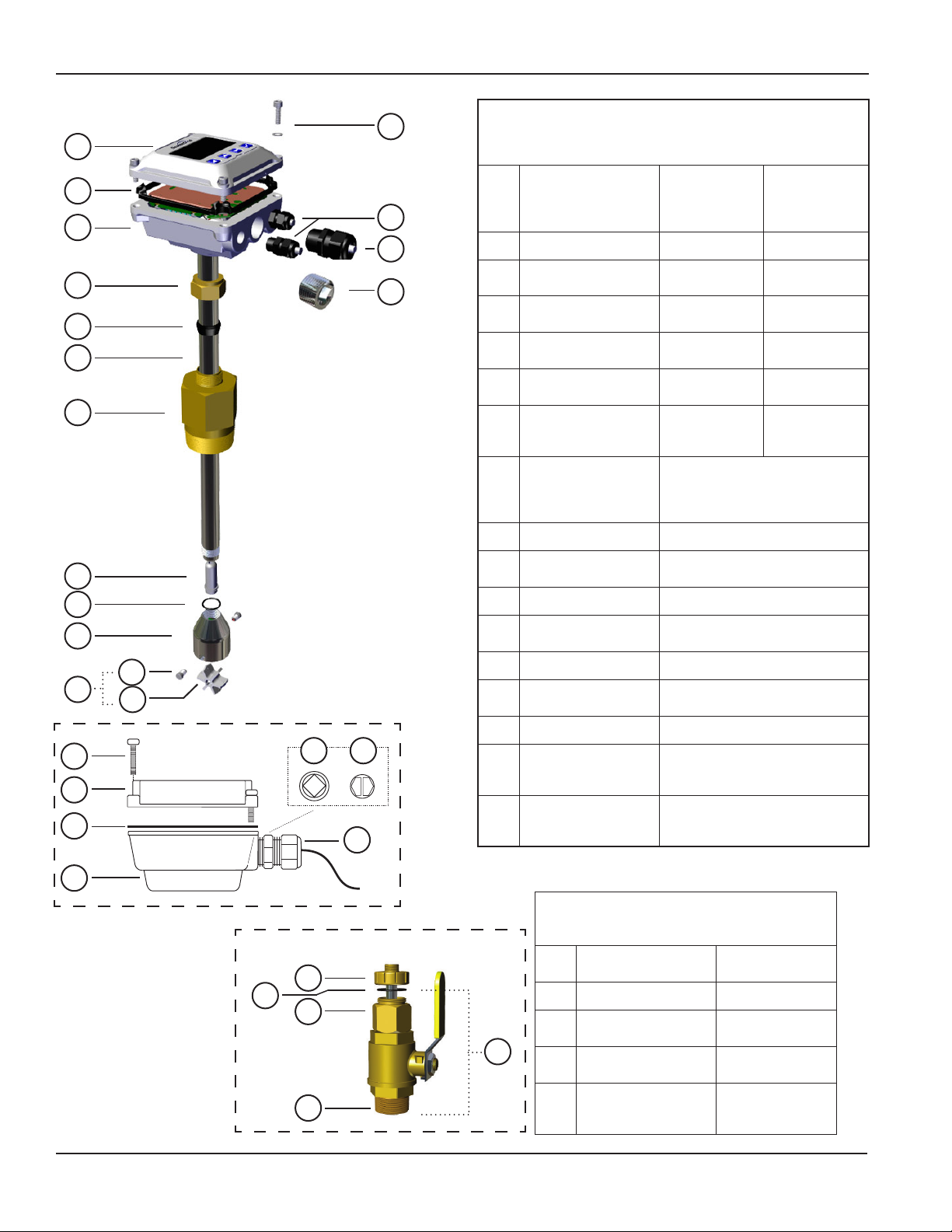
OPERATION AND MAINTANENCE
IP100/200 SERIES INSTRUCTIONS
1a
2a
3a
10
11
12
13
14
17
4b
1b
2b
4a
1 Upper housing/
electronics
6a
7a
2 Housing gasket/seal 102025 100411
3 Lower housing Not eld
5a
4 Housing screw/washer
kit (4 each)
5 Plug, steel (battery
9
units)
6 Strain relief kit, small
(includes 2)
7 Strain relief kit, large
(includes 1) (externally
powered units)
8 Sensor pickup 100508 (Micropower, gray cable,
9 Tube Not eld replaceable
10 Compression nut 100064 (brass)
8
11 Compression ferrule 100358
12 Adapter 100845 (brass)
15
16
Blue Housing
5b
6b
13 Rotor housing o-ring 100218 (EPDM)
14 Rotor housing 100068 (brass)
15 Bearings (includes 2) 103315
16 Rotor with shaft 100035 (Kynar®/tungsten carbide)
17 Rotor repair kit (#15 &
#16 above)
7b
White Housing
1a thru 7a
Contact service
representative
for your specic
model
replaceable
100414 100414
100360 100360
100364 100364
101850 101850
FT450)
100419 (Standard, blue cable,
FT430/440)
100084 (ss)
100846 (ss)
100118 (ss)
100036 (Kynar®/ceramic)
100435 (Kynar®/silicone carbide)
100317 (Kynar®/tungsten carbide)
100043 (Kynar®/ceramic)
100556 (Kynar®/silicone carbide)
Blue Housing
1b thru 7b
Contact service
representative
for your specic
model
Not eld
replaceable
IP 11x/21x Parts
3b
IP 15x/25x Parts (Hot Tap)
All parts are the same except those below, which
Hot Tap
A
B
C
E
D
Seametrics • 253.872.0284 Page 14 seametrics.com
replace #12
A Locking collar 100061 (brass)
B Adapter tting O-ring 100345 (EPDM)
C Adapter, hot tap 100384 (brass)
D Nipple, 2 inch 100066 (brass)
E Valve assembly
(includes valve plus B,
C, & D above)
100116 (ss)
100385 (ss)
100103 (ss)
100069 (brass)
100119 (ss)
Page 15

TROUBLESHOOTING
IP100/200 SERIES INSTRUCTIONS
Problem Probable Cause Things to Try...
No pulse output Below minimum ow cutoff Check velocity vs. pipe size (see page 8)
Empty pipe Check plumbing
No power Check connections
Output pulses incorrect Incorrect depth setting Check depth setting (see page 7)
Pipe not full Refer to installation recommendations
(see pages 5 and 10)
Not enough straight pipe Refer to installation recommendations
(see pages 5 and 9)
Jumpy reading Fluctuating ow rate Refer to installation recommendations
(see pages 5 - 10)
Fluctuating around low ow cutoff Check velocity vs. pipe size (see page 8)
Not enought straight pipe Refer to installation recommendations
(see pages 5 and 9)
Seametrics • 253.872.0284 Page 15 seametrics.com
Page 16

SEAMETRICS LIMITED WARRANTY
IP100/200 SERIES INSTRUCTIONS
The limited warranty set forth below is given by Seametrics, with respect to Seametrics and INW brand products purchased in the
United States of America.
Seametrics warrants that products manufactured by Seametrics, when delivered to you in new condition in their original containers
and properly installed, shall be free from defects in material and workmanship. Seametrics products are warranted against
defects for a period of two (2) years from date of installation, with proof of install date. If no proof of install date can be
provided, warranty period will be two (2) years from date of shipment from Seametrics, as dened on Seametrics’ invoice.
Seametrics’ obligation under this warranty shall be limited to replacing or repairing the part or parts, or, at Seametrics’ option, the
products, which prove defective in material or workmanship. The following are the terms of Seametrics’ limited warranty:
a. Buyer must give Seametrics prompt notice of any defect or failure and satisfactory proof thereof.
b. Any defective part or parts must be returned to Seametrics’ factory or to an authorized service center for inspection.
c. Buyer will prepay all freight charges to return any products to Seametrics’ factory, or another repair facility. as designated by
Seametrics.
d. Defective products, or parts thereof, which are returned to Seametrics and proved to be defective upon inspection, will be
repaired to factory specications.
e. Seametrics will deliver repaired products or replacements for defective products to the buyer (ground freight prepaid) to the
destination provided in the original order.
f. Products returned to Seametrics for which Seametrics provides replacement under this warranty shall become the property
of Seametrics.
g. This limited warranty covers all defects encountered in normal use of Seametrics products, and does not apply to the
following cases:
i. Loss of or damage to Seametrics product due to abuse, mishandling, or improper packaging by buyer
ii. Failure to follow operating, maintenance, or environmental instructions prescribed in Seametrics’ instruction manual
iii. Products not used for their intended purpose
iv. Alterations to the product, purposeful or accidental
v. Electrical current uctuations
vi. Corrosion due to aggressive materials not approved for your specic product
vii. Mishandling, or misapplication of Seametrics products
viii. Products or parts that are typically consumed during normal operation
ix. Use of parts or supplies (other than those sold by Seametrics) which cause damage to the products, or cause
abnormally frequent service calls or service problems
h. A new warranty period shall not be established for repaired or replaced material, products, or supplied. Such items shall
remain under warranty only for the remainder of the warranty period on the original materials, products, or supplies.
i. In the event that equipment is altered or repaired by the buyer without prior written approval by Seametrics, all warranties
are void. Damage caused by equipment or accessories not manufactured by Seametrics may void the product’s warranty.
j. SOFTWARE: The Seller grants the user a non-exclusive license to use Seametrics’ software, according to the following
limitations and conditions:
i. The user may install the software on one or more desktop or laptop computers.
ii. All title and intellectual rights to the software are owned by Seametrics.
iii. No copies may be made or distributed except as described above.
iv. The user may not modify or reverse-engineer the software.
THE FOREGOING WARRANTY IS IN LIEU OF ALL OTHER WARRANTIES, WHETHER ORAL, WRITTEN, EXPRESSED, IMPLIED OR STATUTORY. NO
IMPLIED WARRANTY, INCLUDING ANY IMPLIED WARRANTY OF MERCHANTABILITY OR FITNESS FOR A PARTICULAR PURPOSE, APPLIED TO
THE PRODUCTS AFTER THE APPLICABLE PERIOD OF THE EXPRESS LIMITED WARRANTY STATED ABOVE, AND NO OTHER EXPRESS WARRANTY
OR GUARANTY, EXCEPT AS MENTIONED ABOVE, GIVEN BY ANY PERSON OR ENTITY WITH RESPECT TO THE PRODUCTS, SHALL BIND
SEAMETRICS. SEAMETRICS SHALL NOT BE LIABLE FOR LOSS OF REVENUES, OR PROFITS, OR INCONVENIENCES, EXPENSE FOR SUBSTITUTE
EQUIPMENT OR SERVICE, STORAGE CHARGES, LOSS OF DATA, OR ANY OTHER SPECIAL, INCIDENTAL, OR CONSEQUENTIAL DAMAGE CAUSED
BY THE USE OR MISUSE OF, OR INABILITY TO USE THE PRODUCTS, REGARDLESS OF THE LEGAL THEORY ON WHICH THE CLAIM IS BASED,
AND EVEN IF SEAMETRICS HAS BEEN ADVISED OF THE POSSIBILITY OF SUCH DAMAGES. IN NO EVENT SHALL RECOVERY OF ANY KIND
AGAINST SEAMETRICS BE GREATER IN AMOUNT THAN THE PURCHASE PRICE OF THE PRODUCT SOLD BY SEAMETRICS AND CAUSING THE
ALLEGED DAMAGE. WITHOUT LIMITING THE FOREGOING, YOU ASSUME ALL RISK OF LIABILITY FOR LOSS, DAMAGE, OR INJURY TO YOU AND
YOUR PROPERTY AND TO OTHERS AND THEIR PROPERTY ARISING OUT OF USE OR MISUSE OF, OR INABILITY TO USE THE PRODUCTS NOT
CAUSED DIRECTLY BY THE NEGLIGENCE OF SEAMETRICS.
SOME STATES DO NOT ALLOW LIMITATIONS ON THE DURATION OF AN IMPLIED WARRANTY, SO THE ABOVE LIMITATIONS MAY NOT
APPLY TO YOU. SIMILARLY, SOME STATES DO NOT ALLOW THE EXCLUSION OR LIMITATIONS OF CONSEQUENTIAL DAMAGE, SO THE ABOVE
LIMITATION OR EXCLUSION MAY NOT APPLY TO YOU. THIS LIMITED WARRANTY GIVES YOU SPECIFIC LEGAL RIGHTS; HOWEVER, YOU MAY
ALSO HAVE OTHER RIGHTS WHICH MAY VARY FROM STATE TO STATE.
Seametrics • 19026 72nd Avenue South • Kent, Washington 98032 • USA
(P) 253.872.0284 • (F) 253.872.0285 • 1.800.975.8153 • seametrics.com
LT-65200042r2.4 20170503
5/3/2017
 Loading...