

Page 1

d
C
INW PT2X
Pressure/Temperature Smart Sensor
and Data Logger Instructions
For PSIG
sensors, refer
to page 18
regarding
desiccant
use!
o
m
e
i
p
f
PROUDLY
MADE
IN THE
USA
i
t
r
e
C
ISO
9001:2008
a
n
y
Page 2

TABLE OF CONTENTS
General Information
General Information ........................................................................................................................................................................Page 3
Dimensions .........................................................................................................................................................................................Page 3
Specications .....................................................................................................................................................................................Page 4
How Pressure Sensors Work ........................................................................................................................................................Page 5
Initial Inspection and Handling ...................................................................................................................................................Page 6
Do’s and Don’ts .................................................................................................................................................................................Page 6
Installation
Connecting External Power ...........................................................................................................................................................Page 7
Connecting a PT2X to a Computer ............................................................................................................................................Page 7
Cable Wiring .......................................................................................................................................................................................Page 8
Installing Aqua4Plus or Aqua4Plus Lite Software ................................................................................................................Page 8
Using Without Aqua4Plus or Aqua4Plus Lite Software .....................................................................................................Page 8
Battery Life Calculator ....................................................................................................................................................................Page 9
Installing the Sensor ........................................................................................................................................................................Page 9
Desiccant Use .....................................................................................................................................................................................Page 9
Grounding Issues ..............................................................................................................................................................................Page 9
Settings and Calibration
Preparation..........................................................................................................................................................................................Page 10
Submergence .....................................................................................................................................................................................Page 11
Depth-to-Water.................................................................................................................................................................................Page 11
Elevation Above Sea Level ............................................................................................................................................................Page 12
Staff Gauge .........................................................................................................................................................................................Page 12
Operation
Collecting Data with Aqua4Plus and Aqua4Plus Lite .........................................................................................................Page 13
Real Time Monitor ............................................................................................................................................................................Page 13
Setting up Data Recording ...........................................................................................................................................................Page 13
Retrieving Data ..................................................................................................................................................................................Page 13
Viewing Data ......................................................................................................................................................................................Page 13
Exporting Data ................................................................................................................................................................................... Page 14
A Word about Units .........................................................................................................................................................................Page 14
Direct Read Modbus/SDI-12
Setting Units for Direct Read .......................................................................................................................................................Page 14
Power Consideration .......................................................................................................................................................................Page 15
Reading via Modbus RTU ..............................................................................................................................................................Page 15
Reading via SDI-12...........................................................................................................................................................................Page 16
Maintenance
Removing Debris from End Cone ...............................................................................................................................................Page 18
Desiccant Tubes.................................................................................................................................................................................Page 18
Sensor/Cable/End Connections ..................................................................................................................................................Page 19
Changing Batteries ...........................................................................................................................................................................Page 19
Appendix: DTW Reference
Entering Depth-to-Water Reference after Data Collection .............................................................................................. Page 23
Troubleshooting
Problems/Probable Causes/Things to Try ............................................................................................................................... Page 26
Warranty
Seametrics Limited Warranty .......................................................................................................................................................Page 27
PT2X INSTRUCTIONS
IF USING ALKALINE BATTERIES—PREVENT BATTERY LEAKAGE!
PT2X sensors are typically shipped with lithium batteries. If, however, you are
using alkaline batteries, be aware that under some circumstances alkaline
batteries can leak, causing damage to the sensor. To prevent leakage, the
following is recommended. (Does not apply to lithium batteries.)
• Change the batteries at least every 18 months.
• If the sensor will not be deployed for 3 months or more, remove the
batteries.
Seametrics • 253.872.0284 Page 2 inwusa.com
Page 3
GENERAL INFORMATION
PT2X INSTRUCTIONS
The INW PT2X Smart Sensor is an integrated data
logger and pressure/temperature sensor and is ideal for
monitoring groundwater, well, tank, and tidal levels, as well
as for pump and slug testing. This sensor networks with
all of the INW Smart Sensor family. Its compatibility with
INW’s Wireless Data Collection technology makes it ideal
for remote monitoring.
The PT2X is a microprocessor based digital intelligent sensor
designed to measure and record pressure, temperature,
and time, using low power, battery operated circuitry.
Pressure is measured with an extremely rugged and stable
piezo-electric media-isolated pressure element combined
with a 16-bit analog-to-digital converter. This provides
extremely accurate and stable pressure input into the
microprocessor on the circuit board.
This industry standard digital RS485 interface device records
up to 520,000 records of pressure/level, temperature, and
time data, operates with low power, and features easy-touse software with powerful features. Constructed with 316
stainless steel or titanium, PTFE, and uoropolymer, this
sensor provides high-accuracy readings in rugged and
corrosive eld conditions.
Two internal 1.5V AA batteries power the PT2X.
(Auxiliary power supplies are available for data intensive
applications.) The unit is programmed using INW’s easyto-use Aqua4Plus or Aqua4Plus Lite control software. Once
programmed the unit will measure and collect data on a
variety of time intervals.
Several PT2Xs, or a combination of PT2Xs and other INW
Smart Sensors, can be networked together and controlled
from one location, either directly from a single computer
or via INW’s Wireless Data Collection System.
While most will use the PT2X with our free, easy-to-use
Aqua4Plus Lite or Aqua4Plus software, it is by no means
limited to that software. You can use your own Modbus
®
RTU or SDI-12 software or logging equipment to read
measurements, thus tying into your existing systems and
databases.
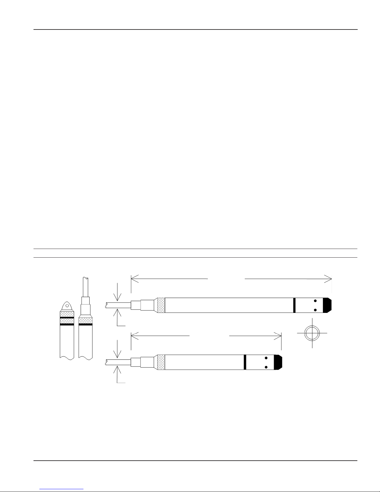
Dimensions
Cableless
0.25” (0.6
cm) Shorter
0.28” (0.7 cm)
0.28” (0.7 cm)
12.18” (30.9 cm)
Battery Version
8.37” (21.3 cm)
Non-Battery Version
Diameter
0.75” (1.9 cm)
Seametrics • 253.872.0284 Page 3 inwusa.com
Page 4

GENERAL INFORMATION
PT2X INSTRUCTIONS
Specications*
Housing & Cable Weight 0.8 lb. (0.4 kg)
Body Material Acetal & 316 stainless or titanium
Wire Seal
Material
Cable Submersible: polyurethane, polyethylene, or ETFE (4 lb./100 ft., 1.8 kg/30 m)
Desiccant 1-3 mm indicating silica gel
Field Connector Standard
Temperature Operating Range Recommended: -15˚ to 55˚C (5˚ to 131˚F) Requires freeze protection kit if using pressure option in water
Storage Range Without batteries: -40˚ to 80˚C (-40˚ to 176˚F)
Power Internal Battery Two lithium ‘AA’ batteries - Expected battery life: 18 months at 15 min. polling interval (may vary do to
Auxiliary 12 Vdc - Nominal, 6-16 Vdc - range
Communication Modbus® RS485 Modbus® RTU, output=32bit IEEE oating point
SDI-12 SDI-12 (ver. 1.3) - ASCII
Logging Memory 4MB - 520,000 records
Logging Types Variable, user-dened, proled
Logging Rates 8x/sec maximum, no minimum
Baud Rates 9600, 19200, 38400
Software Complimentary Aqua4Plus and Aqua4Plus Lite
Networking 32 available addresses per junction (Address range: 1 to 255)
File Formats .a4d and .csv (also .xls in Windows 8 and earlier)
Output Channels Temperature Depth/Level¹
Element Digital IC on board Silicon strain gauge transducer, 316 stainless or Hastelloy
Accuracy ±0.5°C — 0° to 55°C (32˚ to 131˚F)
Resolution 0.1˚C 0.0034% FS (typical)
Units Celsius, Fahrenheit, Kelvin PSI, FtH₂O, inH₂O, mmH₂O, mH₂O, inH₂O, cmHg, mmHg, Bars, Bars,
Range -15˚ to 55˚C (5˚ to 131˚F) Gauge
Compensated --- 0˚ to 40˚C (32˚ to 104˚F)
Max operating pressure 1.1 x full scale
Over pressure protection 3x full scale up to 300psi - for > 300psi (650 ft or 200 m) contact factory
Burst pressure 1000 psi (approx. 2000 ft or 600 m)
Environmental IP68, NEMA 6P
Fluoropolymer and PTFE
below freezing.
environmental factors)
±2.0°C — below 0°C (32˚F)
±0.05% FSO (typical, static)
±0.1% FSO (maximum, static)
(B.F.S.L. 20˚C)
kPa
PSI: 12, 5, 15, 30, 50, 100, 300
FtH₂O: 2.32, 12, 35, 69, 115, 231, 692
Absolute³
mH₂O: 0.72, 3.5, 10.5, 21, 35, 70, 210
PSI: 30, 50, 100, 300
FtH₂O: 35, 81, 196, 658
mH₂O: 10, 24, 59, 200
*Specications subject to change. Please consult out web site for the most current data (inwusa.com).
Modbus is a registered trademark of Schneider Electric.
1 Higher pressure ranges available upon request
2 ±0.25% accuracy FSO (max) at this range
3 Depth range for absolute sensors has 14.7 PSI subtracted to give actual depth allowed.
Seametrics • 253.872.0284 Page 4 inwusa.com
Page 5
GENERAL INFORMATION
PT2X INSTRUCTIONS
How Pressure Sensors Work
Liquids and gasses do not retain a xed shape. Both
have the ability to ow and are often referred to as
uids. One fundamental law for a uid is that the uid
exerts an equal pressure in all directions at a given level.
Further, this pressure increases with an increasing depth of
“submergence”. If the density of a uid remains constant
(noncompressible...a generally good assumption for water
at “normal” pressures and temperatures), this pressure
increases linearly with the depth of “submergence”.
We are all “submerged” in the atmosphere. As we increase
our elevation, the pressure exerted on our bodies decreases
as there is less of this uid above us. It should be noted
that atmospheric pressure at a given level does vary
with changes in the weather. One standard atmosphere
(pressure at sea level at 20º C) is dened to be 14.7 PSI
(pounds per square inch).
There are several methods to reference a pressure
measurement. Absolute pressure is measured with respect
to an ideal vacuum (no pressure). Gauge pressure is the
most common way we express pressure in every day life
and is the pressure exerted over and above atmospheric
pressure. With this in mind, gauge pressure (Pg) can be
expressed as the difference between the absolute pressure
(Pa) and atmospheric pressure (Patm):
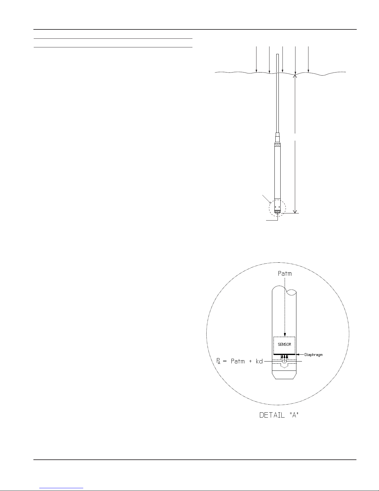
Water Line
P = Patm + kd
A
Patm
d
“A”
Pressure Diagram: See Detail A.
Pg = Pa - Patm.
To measure gauge pressure, atmospheric pressure is
subjected to one side of the system and the pressure to be
measured is subjected to the other. The result is that the
differential (gauge pressure) is measured. A tire pressure
gauge is a common example of this type of device.
Recall that as the level of submergence increases (in a
noncompressible uid), the pressure increases linearly.
Also, recall that changes in weather cause the absolute
atmospheric pressure to change. In water, the absolute
pressure (Pa) at some level of depth (d) is given as follows:
Pa = Patm + kd
where k is simply a constant
(i.e.: 2.307 feet of water = 1 PSI)
INW’s standard gauge submersible pressure devices utilize
a vent tube in the cable to allow the device to reference
atmospheric pressure. The resulting gauge pressure
measurement reects only the depth of submergence.
That is, the net pressure on the diaphragm is due entirely
to the depth of submergence.
Seametrics • 253.872.0284 Page 5 inwusa.com
Absolute pressure is given as Pa = Patm + kd
(where k is 2.307 feet of water)
Page 6
GENERAL INFORMATION
PT2X INSTRUCTIONS
Initial Inspection and Handling
Upon receipt of your smart sensor, inspect the shipping package for damage. If any damage is apparent, note the signs
of damage on the appropriate shipping form. After opening the carton, look for concealed damage, such as a cut cable.
If concealed damage is found, immediately le a claim with the carrier.
Check the etched label on the sensor to be sure that the proper range and type were provided. Also check the label
attached to the cable at the connector end for the proper cable length.
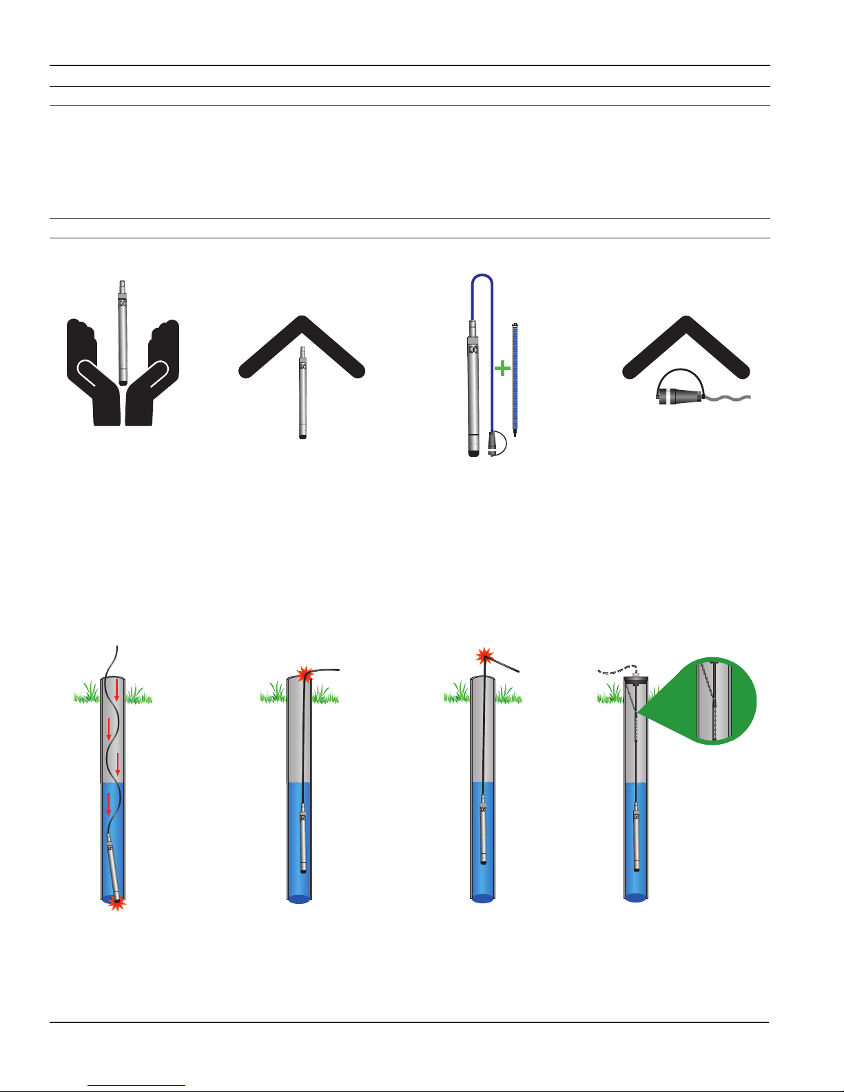
Do’s and Don’ts
Do handle sensor with
care
Do store sensor in a
dry, inside area when
not in use
Do install a desiccant
tube if using a gauge
sensor
Do install sensor so the
connector end is kept
dry
Don’t drop into well
Lower gently to prevent
damage
Seametrics • 253.872.0284 Page 6 inwusa.com
Don’t scrape cable
over edge of well
May nick or fray the
cable
Don’t bend cable sharply
May close off vent tube
and/or weaken internal
wires
Don’t support sensor
with the connector
Use a strain relief device
Page 7
INSTALLATION
PT2X INSTRUCTIONS
Connecting External Power
The PT2X comes with two 1.5V AA internal batteries.
If auxiliary power is desired, you can use a 6–16 VDC supply
that can provide 15 mA. Connect to Vaux++ (pin 1 - white)
and Ground (pin 5 - blue) or contact INW for auxiliary
power supplies.
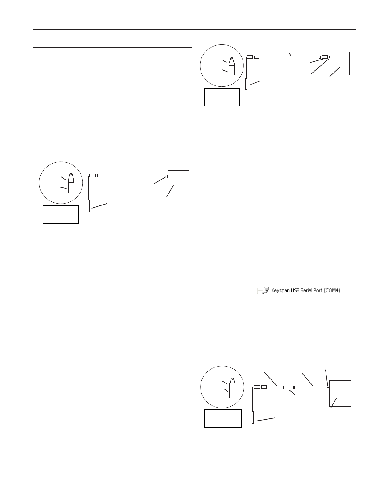
Connecting the PT2X to a Computer
Cabled sensors are terminated with a weather-resistant
connector. Cableless sensors are terminated with a weatherresistant connector that is inside a screw-cap. Connect the
weather-resistant connector to your computer’s USB port
as shown below.
USB to RS485
Adapter
Screwcap
Sensor
Sensor
Cableless
Conguration
USB Port
PC or Laptop
Computer
Connecting sensor to your computer using
INW’s USB to RS485 adapter.
Aqua4Plus and Aqua4Plus Lite communicate with the
sensor using the USB to RS485 adapter cable. This cable
requires drivers to be installed on your computer. If you
are connected to the Internet when you rst plug in the
cable, it will normally obtain and install the correct drivers
automatically. If this does not happen, or if you do not have
Internet connection, you can use Aqua4Plus or Aqua4Plus
Lite to install the drivers. In Aqua4Plus, select Install USB/
RS485 Drivers from the Utilities menu; in Aqua4Plus Lite,
select the same from the Program Conguration menu.
Select your operating system, and then click Install.
Alternate Connection Options
INW recommends connecting the sensor to your computer
using the INW USB cable. However, when using Aqua4Plus,
the sensor can also be connected using an RS232 serial
port or a USB-to-Serial cable, as described below. (Note:
Aqua4Plus Lite can only communicate using the INW USB
cable.)
Connecting via RS232 Serial Port
Connect the weather-resistant connector to your
computer’s serial port as shown below.
Interface Cable
Screwcap
Sensor
Cableless
Conguration
Sensor
RS485/RS232
Adapter
Serial Port
PC or Laptop
Computer
Connecting sensor to your computer using
an RS485/RS232 adapter and an interface cable.
Connecting with a USB/Serial Adapter
USB-to-Serial cables are readily available from many
electronics and computer stores, as well as numerous
sites on the Internet. INW has tested and recommends the
Keyspan USA-19HS. Install as follows:
• Plug into USB port.
• Install the drivers provided with the particular unit.
• Determine the port number to which the adapter is
assigned.
• Right-click on My Computer.
• From the popup menu, select Manage to open
the Computer Management window.
• On left panel, click on Device Manager.
• On right panel, double-click on Ports.
• A list of active COM ports will be displayed. Note
the COM number assigned to the adapter you
just installed.
For example:
• Close Manager.
• Connect to the sensor.
• On the Aqua4Plus software, select the COM port
noted above. (If you do not see your new COM port
in the dropdown box, open the Communications
dialog box from the Options menu. Increase the
Highest COM port number, up to a maximum of
15.)
USB Port
PC or Laptop
Computer
Screwcap
Sensor
Cableless
Conguration
Interface
Cable
USB-to-Serial
Adapter
RS232/RS485
Adapter
Sensor
Connecting sensor to your computer using
a USB to Serial adapter and an interface cable.
Seametrics • 253.872.0284 Page 7 inwusa.com
Page 8
INSTALLATION
PT2X INSTRUCTIONS
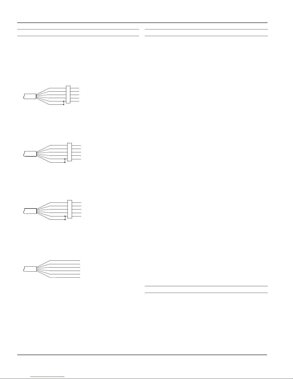
Cable Wiring
If you buy your cabled sensor with a connector installed
(the normal conguration), no further wiring is needed.
For reference purposes, the rst three diagrams below
show the pinout from the connector for various scenarios.
The nal diagram shows the pinout if you bought your
sensor without a connector for use with SDI-12.
White
Purple
Yellow
Brown
Blue
Shield
1
2
3
4
5
5-Pin
Connector
12 VDC+ (Vaux)
Modbus DModbus D+
Digital I/O (Not used)
12 VDC- (GND)
For Modbus® with rmware lower than 2.0
— with 5-pin connector
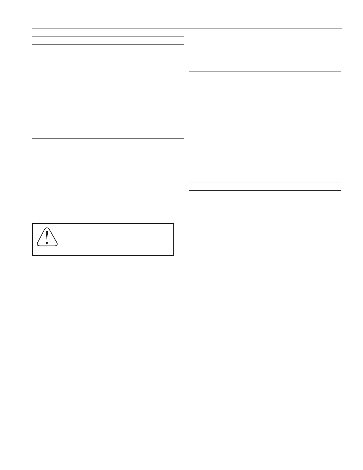
White
Purple
Yellow
Brown
Blue
Shield
1
2
3
4
5
5-Pin
Connector
12 VDC+ (Vaux)
Modbus DModbus D+
SDI-12 (Not used)
12 VDC- (GND)
For Modbus® with rmware 2.0 or higher
— with 5-pin connector
White
Purple
Yellow
Brown
Blue
Shield
1
2
3
4
5
5-Pin
Connector
12 VDC+ (Vaux)
Modbus D- (Not used)
Modbus D+ (Not used)
SDI-12 Signal
12 VDC- (GND)
For SDI-12 with rmware 2.0 or higher
— with 5-pin connector
White
Purple
Yellow
Brown
Blue
Shield
12 VDC+ (Vaux)
Modbus D- (Not used)
Modbus D+ (Not used)
SDI-12 Signal
12 VDC- (GND)
Earth ground
Installing Aqua4Plus or Aqua4Plus Lite Software
The PT2X comes with the Aqua4Plus or Aqua4Plus Lite host
software that is installed on your PC or laptop. Use this
software to program the datalogger, to retrieve data from
the logger, to view collected data, and to export data to
external les for use with spreadsheets or databases.
Refer to the software manuals for details on installing and
using Aqua4Plus or Aqua4Plus Lite.
Setting the Continuous Rate
The PT2X can take readings more often than once per
second. This is known as a “continuous rate.” Set the
continuous rate for the PT2X from the Congure Menu |
Sensor Continuous Rate.
Firmware Version Available Settings
1.0 and above Exactly 2, 4, or 8 readings per second
0.22, 0.23, 0.24 Approximately 2,3,4,5,6, or 10 readings per
second
0.18 Approximately 10 readings per second
To use the continuous rate during recording, enter a “c” or
a zero in the Polling Interval on the Logging Schedule.
Setting the Filter
The PT2X has the ability to apply ltering to incoming data
in order to smooth out minor variations in readings. This
lter can be from 1 (no ltering) to 8 (maximum ltering.)
Different versions of rmware have different ltering
options as shown below. For further information on PT2X
data ltering, see INW application note Filter Response on
PT2X Smart Sensor.
Firmware Version Filtering
1.3 and above Can be set from 1 (no ltering) to 8 (maximum
ltering) from the Advanced option on the
Congure Menu — defaults to 1. (Cannot be
reset from Aqua4Plus Lite.)
1.0 - 1.2 Filter is set to 1 (no ltering). Adjustable ltering
can be obtained by upgrading to a higher
rmware version.
0.24 Filter is permanently set to 1 (no ltering).
0.23 and lower Filtering is permanently set to 8 (maximum).
For SDI-12 with rmware 2.0 or higher
— without connector
Seametrics • 253.872.0284 Page 8 inwusa.com
Using the PT2X Without Aqua4Plus or Aqua4Plus Lite
Most users will use the PT2X with INW’s Aqua4Plus or
Aqua4Plus Lite software. However, the PT2X is quite
versatile, communicating via either Modbus® or SDI-12
interfaces, allowing you to do the following:
• Read a PT2X via Modbus® using your own software.
• Read a PT2X via SDI-12 protocol.
• Display readings from a PT2X on a panel meter.
If you want to use one of these methods, see page 14.
Page 9
INSTALLATION
PT2X INSTRUCTIONS
Battery Life Calculator
IMPORTANT NOTE for PT2X sensors with rmware 2.13 or
higher!
PT2Xs with rmware version 2.13 and higher have a battery
life calculator that is set at the factory when batteries are
rst put in the sensor. If the battery life calculator is not
reset, the remaining life information will be incorrect.
If you need to replace the batteries, see the Maintenance
section in this manual for replacement information and for
information on resetting the battery life calculator.
Installing the Sensor
The PT2X measures pressure. The most common application
is measuring liquid levels in wells and tanks. In order to do
this, the sensor must be installed below the water level at a
xed depth. The installation depth depends on the range
of the sensor. One (1) PSI is equal to approximately 2.31
feet of water. If you have a 5 PSI sensor, the range is 11.55
feet of water and the sensor should not be installed at a
depth below 11.55 feet. If the sensor is installed below its
maximum range, damage may result to the sensor and the
output reading will not be correct.
Note: If you are using an absolute sensor and
you want to enter a depth-to-water reference
after data is collected, then see Appendix
before proceeding.
• Lower the sensor to the desired depth.
• Fasten the cable to the well head using a weather
proof strain-relief system. When securing a vented
cable, make sure not to pinch the cable too tightly
or the vent tube inside the cable jacket may be
sealed off.
• Take a measurement to insure the sensor is not
installed below its maximum range.
Be sure the supplied cap is securely placed on the weatherresistant connector at the top of the cable. Do not install
such that the connector might become submerged with
changing weather conditions. The connector can withstand
incidental splashing but is not designed to be submerged.
For vented sensors, install the sensor so that the desiccant
tube will not ood or lie in water.
sensor is being installed in a uid environment other than
water, be sure to check the compatibility of the uid with
the wetted parts of the sensor.
Desiccant Use
On vented sensors a desiccant tube prevents moisture in
the air from being sucked into the vent tube, which can
cause erratic readings and sensor damage.
The desiccant tube is lled with blue silica gel beads. A
locking barb and a hydrophobic water lter are attached to
the end of the desiccant tube. This lter prolongs the life of
the desiccant as much as three times over a desiccant tube
without the lter.
Install the sensor so that the desiccant tube and cable
connector will not ood or lie in water.
The desiccant is a bright blue color when active and dry. See
Maintenance section for care and changing of desiccant.
Grounding Issues
It is commonly known that when using electronic
equipment, both personnel and equipment need to be
protected from high power spikes that may be caused by
lightning, power line surges, or faulty equipment. Without
a proper grounding system, a power spike will nd the path
of least resistance to earth ground—whether that path is
through sensitive electronic equipment or the person
operating the equipment. In order to ensure safety and
prevent equipment damage, a grounding system must be
used to provide a low resistance path to ground.
When using several pieces of interconnected equipment,
each of which may have its own ground, problems with
noise, signal interference, and erroneous readings may be
noted. This is caused by a condition known as a Ground
Loop. Because of natural resistance in the earth between
the grounding points, current can ow between the points,
creating an unexpected voltage difference and resulting
erroneous readings.
The single most important step in minimizing a ground loop
is to tie all equipment (sensors, dataloggers, external power
sources, and any other associated equipment) to a single
common grounding point. Seametrics recommends
connecting the shield to ground at the connector end.
The sensor can be installed in any position; however, when
it leaves the factory it is tested in the vertical position.
Strapping the sensor body with tie wraps or tape will
not hurt it. INW can provide an optional 1/4” NPT input
adapter which is interchangeable with the standard end
cone for those applications where it is necessary to directly
attach the sensor to a pipe, tank, or other pipe port. If the
Seametrics • 253.872.0284 Page 9 inwusa.com
Page 10
SETTINGS AND CALIBRATION
To adjust sensor offsets, calibration, depth-to-water,
elevation, and other various settings, select the Settings
and Calibration option on the Congure Menu (Aqua4Plus)
or click the Settings button (Aqua4Plus Lite). In the Settings
and Calibration window, click on the channel you want to
adjust. Specic instructions for each channel are displayed
in the right panel. Settings and calibration values can only
be changed when there is no data on the sensor. Be sure
to retrieve any data and then erase the data on the sensor
before proceeding.
The temperature channel rarely needs adjustment. If you
think your temperature channel needs calibrating, contact
your service representative.
Before leaving the factory, your PT2X has been inspected
using precision instruments. However, you may want to
change some of the settings for the pressure channel for
the following reasons:
• To set a specic zero-reference point for
submergence
• To return values as depth-to-water
• To return values as elevation in relation to sea-level
• To return values relative to a staff gauge
PT2X INSTRUCTIONS
Sample Setting and Calibration Window
Preparation
• Run Aqua4Plus Lite or Aqua4Plus and scan for
sensors.
• On the Sensor Map, click the sensor you want to
adjust.
• From Aqua4Plus Lite:
• Select the units you want to use for
measurements, i.e., psi, feet of water, inches of
mercury, etc. Set this from the Congure Menu |
Program Conguration | Set Computer Display
Units.
• Open the Settings and Calibration window by
clicking on the Settings button.
• From Aqua4Plus:
• Select the units you want to use for
measurements, i.e., psi, feet of water, inches of
mercury, etc. Set this from the Options Menu |
Display Units.
• Open the Settings and Calibration window from
the Congure Menu | Settings and Calibration.
Step-by-step instructions will be displayed on the right
side of the window.
The basic setting/calibration process for pressure channels
is as follows. See following pages for detailed instructions.
1. Select the Pressure channel.
2. Enter a Channel Label, if desired.
3. Select the desired type of setting. A picture will
display illustrating the type of selection. Available
types:
• Depth/Submergence
• Depth-to-Water
• Elevation
• Staff Gauge
4. Supply any requested information.
5. Within the Calculator, supply any requested
information.
6. Click the Measure button to get a current
measurement from the sensor.
7. Click the Apply button to accept the new slope and
offset.
8. Click the OK button, to save your changes to the
sensor.
Seametrics • 253.872.0284 Page 10 inwusa.com
Page 11

SETTINGS AND CALIBRATION
PT2X INSTRUCTIONS
Submergence
One-Point Calibration:
-- Computing Offset --
• Place sensor in the uid you are measuring at a precise
known level.
• In the Ref box for the rst point, enter this level or
pressure.
• Click rst Measure button.
• When readings have stabilized, click the Accept button in
the pop-up box.
-- Applying Offset --
• Click the Apply button to apply calculated offset.
• The calculated offset will be transferred to the offset eld
near the top of the window.
• Click OK to save the value to the sensor!!!
Two-Point Calibration:
-- Compute First Calibration Point --
• Place sensor in the uid you are measuring at a precise
known level.
• In the Ref box for the rst point, enter this level or
pressure.
• Click rst Measure button.
• When readings have stabilized, click the Accept button in
the pop-up box.
-- Compute Second Calibration Point --
• Place sensor in the uid you are measuring at a second
precise known level.
• In the Ref box for the second point, enter this level or
pressure.
• Click second Measure button.
• When readings have stabilized, click the Accept button in
the pop-up box.
-- Applying Slope and Offset --
• Click the Apply button to apply calculated values.
• The calculated slope and offset will be transferred to the
elds near the top of the window.
• Click OK to save the value to the sensor!!!
-- Verifying Settings --
• Using the Real Time Monitor, take a few readings to verify
it is reading as expected.
Depth-to-Water
When using the Depth-to-Water setting, you may want
to change the channel label at the top of the Settings
window to read “Depth” or “Depth-to-Water”.
Note: If you have a cableless sensor or want to enter a
depth-to-water reference after data collection for an
absolute cabled sensor, see Appendix.
Cabled Sensors Only
Important! Be sure to use the same units for all
measurements in this calculation. For example, if you have
the program set to display in Ft H2O then be sure to enter
the barometric pressure and depth-to-water readings in
Ft H2O.
-- Computing Offset --
• If you are using an absolute sensor, enter the current
barometric pressure in the Barometric box.
• Place the sensor in the well.
• Using a water level indicator or other measuring device,
determine the depth-to-water from the top of the well
(or other reference point).
• Enter this value in the DTW box.
• Click the Measure button.
• When readings have stabilized, click the Accept button
in the pop-up box.
-- Applying the Slope and Offset --
• Click the Apply button to apply the calculated values.
• The calculated slope and offset will be transferred to the
elds near the top of the window.
• Click OK to save the values to the sensor!!!
-- Verifying Settings --
• Using the Real Time Monitor, take a few readings to
verify it is reading as expected.
IMPORTANT NOTE!
When taking readings on an absolute sensor,
you will need to ADD the current barometric
pressure to get depth-to-water. See the
Barometric Compensation Utility Application
Note (LT-14304) for information on how the
Barometric Utility can help automate this
process.
IMPORTANT NOTE!
When taking readings on an absolute sensor,
you will need to SUBRACT the current
barometric pressure to get submergence. See
the Barometric Compensation Utility Application
Note (LT-14304) for information on how the
Barometric Utility can help automate this process.
Seametrics • 253.872.0284 Page 11 inwusa.com
Page 12

SETTINGS AND CALIBRATION
PT2X INSTRUCTIONS
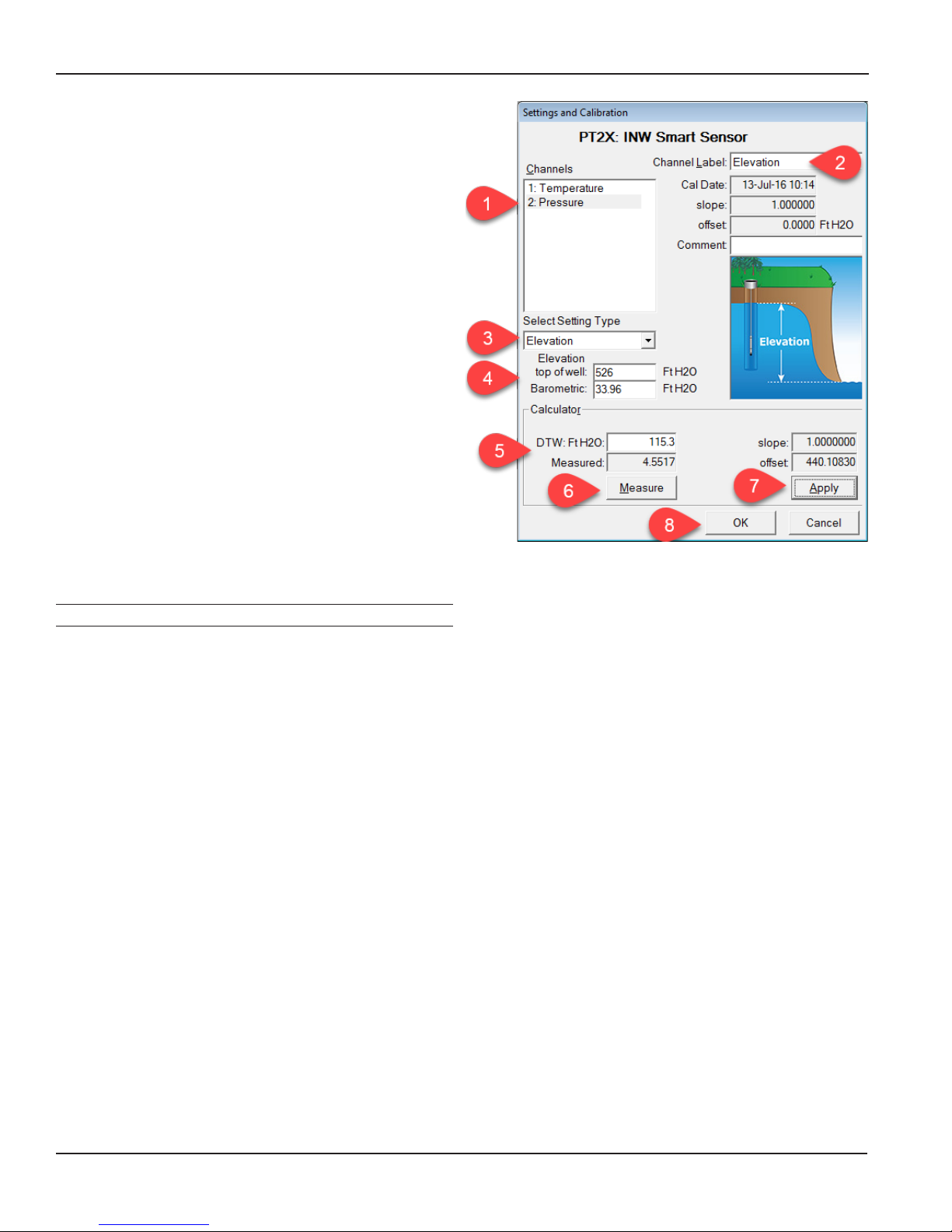
Elevation Above Sea Level
When using the Elevation setting, you may want to change
the channel label at the top of the Settings window to read
“Elevation”.
Important! Be sure to use the same units for all
measurements on this screen. For example, if you have the
program set to display in Ft H2O then be sure to enter
the elevation, barometric pressure, and depth-to-water in
Ft H2O.
-- Computing Offset --
• Enter the elevation of the top of the well (or other
reference point).
• If using an absolute sensor, enter the current barometric
pressure in the Barometric box.
• Place the sensor in the well.
• Using a water level indicator or other measuring device,
determine the depth-to-water from the top of the well (or
other reference point).
• Enter this value in the DTW box.
• Click the Measure button.
• When readings have stabilized, click the Accept button in
the pop-up box.
-- Applying Offset --
• Click the Apply button to apply the calculated offset.
• The calculated offset will be transferred to the offset eld
near the top of the window.
• Click OK to save the values to the sensor!!!
-- Verifying Settings --
• Using the Real Time Monitor, take a few readings to verify
it is reading as expected.
IMPORTANT NOTE!
When taking readings on an absolute sensor,
you will need to SUBRACT the current
barometric pressure to get elevation. See the
Barometric Compensation Utility Application
Note (LT-14304) for information on how the
Barometric Utility can help automate this process.
Staff Gauge
When using the Staff Gauge setting, you may want to
change the channel label at the top of the Settings window
to read “Staff Gauge”.
Important! Be sure to use the same units for all
measurements on this screen. For example, if you have the
program set to display in Ft H2O then be sure to enter the
barometric pressure and staff gauge readings in Ft H2O.
-- Computing Offset --
• If using an absolute sensor, enter the current barometric
pressure in the Barometric box.
• Place the sensor in the well.
• Note the current level on your staff gauge.
• Enter this value in the Staff box.
• Click the Measure button.
• When readings have stabilized, click the Accept button in
the pop-up box.
-- Applying Offset --
• Click the Apply button to apply the calculated offset.
• The calculated offset will be transferred to the offset eld
near the top of the window.
• Click OK to save the values to the sensor!!!
-- Verifying Settings --
• Using the Real Time Monitor, take a few readings to verify
it is reading as expected.
IMPORTANT NOTE!
When taking readings on an absolute sensor, you
will need to SUBRACT the current barometric
pressure to get a staff gauge reading. See the
Barometric Compensation Utility Application
Note (LT-14304) for information on how the
Barometric Utility can help automate this process.
Seametrics • 253.872.0284 Page 12 inwusa.com
Page 13

OPERATION
PT2X INSTRUCTIONS
Collecting Data with Aqua4Plus & Aqua4Plus Lite
Following is a brief overview on using Aqua4Plus/
Aqua4Plus Lite to collect data. Please refer to the software
instruction manuals for further details on conguring and
using Aqua4Plus/Aqua4Plus Lite.
Real Time Monitor
• Click Single to get a single reading.
• Click Start to get a reading once a second for 60
seconds.
• Click Stop to stop the reading.
Note: These are snapshot readings and are not recorded
on the sensor. On sensors with rmware versions lower
than 2.0, the pressure is displayed in the rst column and
temperature in the second. On sensors with rmware
versions 2.0 and higher, the temperature is displayed in the
rst column and pressure in the second.
Retrieving Data from the Sensor/Datalogger
• Click on the le you want to retrieve.
• Click the tool button.
• Select a le location.
• Click Save.
• Click Start.
Select the
data le to
retrieve.
Viewing Data
• Click the or tool button to view data as
a table.
• Click the tool button to view data as a graph.
• Navigate to the desired le, then click the Open
button.
The Real Time Monitor gives a snapshot of the
current readings on the sensor.
Setting up Data Recording
Click the tool button. A Logging Schedule Window will
open. Refer to the software instruction manuals for details
in describing your schedule. Click the Start button to save
the schedule to the sensor and begin recording.
Using the Logging
Schedule Window,
describe the test
steps for your
particular test.
The File Display
window displays
your data in a
tabular format.
The Graph
window displays
your data on an
X Y coordinate
graph.
Seametrics • 253.872.0284 Page 13 inwusa.com
Page 14

OPERATION/DIRECT READ MODBUS/SDI-12
PT2X INSTRUCTIONS
Exporting Data to .csv or .xls Files*
• Click the or tool button to view data as
a table.
• Click on the tool button.
• Select a le location and enter a name for the le.
• Select a le type.
• Click Save.
* When using Windows 10, les can only be exported in .csv format. They
can then be opened manually from Excel or any other spreadsheet or
database program
A Word About Units
Readings from the PT2X Smart Sensor can be displayed in
various units, such as PSI, Ft. H2O, or mm H2O for pressure,
or degrees Celsius or degrees Fahrenheit for temperature.
Select the units you want from the Options | Display Units
menu or from the Congure Menu | Program Conguration
| Set Computer Display Units.
DIRECT READ (MODBUS® OR SDI-12)
While the PT2X comes with INW’s easy to use Aqua4Plus
or Aqua4Plus Lite software, you can also use standard
Modbus® RTU or SDI-12 equipment to easily take readings,
so as to tie into your existing equipment or networks.
You may need to use Aqua4Plus/Aqua4Plus Lite to make
a few settings prior to directly reading the PT2X with your
equipment. These might include the units for the returned
values and/or the Modbus baud rate. These are described
in the following sections.
For Modbus direct read, you must have PT2X rmware 1.5
or higher. For SDI-12, you must have rmware 2.0 or higher.
Setting Units for Direct Read
By default, the PT2X uses the following units:
Temperature Degrees Celsius
Pressure PSI
If you want to change to different units, for example,
degrees Fahrenheit for temperature or feet of water for
pressure, set these units using Aqua4Plus/Aqua4Plus Lite.
• From Aqua4Plus select Direct Read Units from the
Congure | Advanced menu.
• From Aqua4Plus Lite select Set Direct Read Units
from the Sensor congure menu.
• On the popup box, click the down-arrows next to
the channel types you want to change, and then
select the units you want.
• Click OK.
Seametrics • 253.872.0284 Page 14 inwusa.com
Select the units for your direct read
measurements, whether Modbus or SDI-12.
Once set, these units are saved on the sensor and direct
readings, either via Modbus or via SDI-12, will return values
using these units. (Note: These settings do not affect the
units used on the Aqua4Plus/Aqua4Plus Lite display. Refer
to the software manual for details.)
Page 15

DIRECT READ MODBUS/SDI-12
PT2X INSTRUCTIONS
Power Consideration
If your sensor does not have internal batteries and is not
powered continuously by an auxiliary power supply, then
you must turn power on to the sensor at least two seconds
before a reading is to be taken to allow the sensor to warm
up.
Reading Via Modbus® RTU
Setting Baud Rate
Your PT2X comes congured to communicate at 38,400
baud, with 8 data bits, one stop bit, and no parity. The
sensor can also be set to 19,200 or 9600 baud, if needed for
your application. You must use Aqua4Plus, not Aqua4Plus
Lite, to make baud rate changes.
If needed, set your PT2X to the desired baud rate as follows:
• Click on the Congure menu, and then select
Advanced.
• From the yout menu, select Sensor Baud Rate. (You
may be asked for a password. Enter admin.)
• On the popup box, click the down-arrow, select the
baud rate you need, and then click OK.
Once you have changed the baud rate on the PT2X, you will
not be able to talk to it with Aqua4Plus until you change
the baud rate for Aqua4Plus, as follows:
Measurement Timing
When you request a reading via Modbus, the sensor wakes
up, returns the current values in the registers, and then
starts taking new readings and updating the registers.
After approximately 10 seconds, if no more readings have
been requested, the sensor goes back to sleep.
Because of this, the rst reading you get will be old. If you
are taking readings at intervals of less than 10 seconds,
simply ignore the rst reading — all remaining readings will
be current. On the other hand, if you are taking readings
at intervals of greater than 10 seconds, take a reading,
ignore it, wait one second, take another reading. Record
this second reading.
Data Format
The data is returned as 32-bit IEEE oating-point values,
highword rst, also referred to as big-endian or oat
inverse.
For further information and detailed Modbus examples,
see INW application note, “Reading INW Smart Sensors
Using Modbus RTU” available from our web site at inwusa.
com.
• Click the Options menu, and then select Baud Rate.
• On the popup box, click the down-arrow, select the
baud rate you need, and then click OK.
The current Aqua4Plus baud rate is displayed in the lower
right corner of the main Aqua4Plus window.
Taking Measurements
Reading Registers
Read measurements using Modbus function 03 – Read
Holding Registers. Readings are located in two registers
each, starting at address 62592. (PT2X register addressing
is zero based, i.e., starts at zero. If your equipment uses one
based addressing, you will need to add one to the register
addresses.)
Addresses for PT2Xs with rmware lower than 2.0
Zero based One based
Pressure 62592 62593
Temperature 62594 62595
Addresses for PT2Xs with rmware 2.0 or higher
Zero based One based
Temperature 62592 62593
Pressure 62594 62595
Seametrics • 253.872.0284 Page 15 inwusa.com
Page 16

OPERATION
PT2X INSTRUCTIONS
Reading Via SDI-12
Note: The default units setting for pressure is PSI. The default units setting for temperature is Celsius.
To change these, use the Direct Read Units in the Aqua4Plus/Aqua4Plus Lite Control Software.
Addressing
Default SDI-12 Address: 0
SDI-12 Command Nomenclature
<a> = Sensor address
{crc} = SDI-12 compatible 3-character CRC
<cr> = ASCII carriage return character
<lf> = ASCII line feed character
highlighted values indicate variable data
All SDI-12 requests consist
of a command followed by
a request for values. Some
software or equipment may
combine these, making the
second one unnecessary. Refer
to your software or equipment
documentation for details.
Request Response
<a>M1! <a>0021<cr><lf>
Address
Command
Request Response
Address
Time until
(in seconds)
response
<a>D0! <a>+7.15863<cr><lf>
Address
values read
Request for
Address
Returned
value(s)
SDI-12 Commands
Sensor Identication
<a>I! <a>13 INWUSA PT2X 213ssssssssss<cr><lf> Note: 213 will change to reect current rmware version.
Acknowledge Active, Address Query
<a>! <a><cr><lf>
?! <a><cr><lf>
ssssssssss = device serial number
Carriage Return
Linefeed
# of values to
be returned
Carriage Return
Linefeed
Change Address
<a>A<b>! <b><cr><lf> Change address to <b>
Request Measurement
<a>M! <a>0022<cr><lf> Request all measurements
<a>D0! <a>+22.0512+12.0512<cr><lf> Read temperature and pressure
<a>M1! <a>0021<cr><lf> Request temperature measurement only
<a>D0! <a>+22.0512<cr><lf> Read temperature
<a>M2! <a>0021<cr><lf> Request pressure measurement only
<a>D0! <a>12.0512<cr><lf> Read pressure
Seametrics • 253.872.0284 Page 16 inwusa.com
Page 17

OPERATION
Request Measurement with CRC
<a>MC! <a>0022<cr><lf> Request all measurements with CRC
<a>D0! <a>+22.0512+12.0512{crc}<cr><lf> Read temperature and pressure
<a>MC1! <a>0021<cr><lf> Request temperature measurement only with CRC
<a>D0! <a>+22.0512{crc} <cr><lf> Read temperature
<a>MC2! <a>0021<cr><lf> Request pressure measurement only with CRC
<a>D0! <a>12.0512{crc} <cr><lf> Read pressure
Concurrent Measurement
<a>C! <a>0022<cr><lf> Request all measurements
<a>D0! <a>+22.0512+12.0512<cr><lf> Read temperature and pressure
<a>C1! <a>0021<cr><lf> Request temperature measurement only
<a>D0! <a>+22.0512<cr><lf> Read temperature
PT2X INSTRUCTIONS
<a>C2! <a>0021<cr><lf> Request pressure measurement only
<a>D0! <a>12.0512<cr><lf> Read pressure
Concurrent Measurement with CRC
<a>CC! <a>0022<cr><lf> Request all measurements with CRC
<a>D0! <a>+22.0512+12.0512{crc}<cr><lf> Read temperature and pressure
<a>CC1! <a>0021<cr><lf> Request temperature measurement only with CRC
<a>D0! <a>+22.0512{crc} <cr><lf> Read temperature
<a>CC2! <a>0021<cr><lf> Request pressure measurement only with CRC
<a>D0! <a>12.0512{crc} <cr><lf> Read pressure
For further information and SDI-12 examples, see INW application note, “PT2X SDI-12 Interface Specication” available
from our web site at inwusa.com.
Seametrics • 253.872.0284 Page 17 inwusa.com
Page 18

MAINTENANCE
PT2X INSTRUCTIONS
Removing Debris from End Cone
At times mud, silt, or other debris may foul the water inlets
to the pressure element. The end cone can be removed to
clean out the debris.
Twist Open Housing
1. Gently twist off end cone portion only - do not twist
off pressure element!
2. Remove debris. Do not poke anything into the
sensor. This can damage the sensor element and
void the warranty.
3. Replace and retighten the end cone.
Pressure element
Water inlet
End cone
Gently twist off the end cone and carefully remove debris
Set Screw Housing
1. Remove the two set screws at the bottom of the
housing tube, using a 1/16” allen wrench.
2. Gently remove the end cone.
3. Remove debris. Do not poke anything into the
sensor. This can damage the sensor element and
void the warranty.
4. Replace the end cone and secure with set screws.
Desiccant Tubes
On vented sensors, inspect the desiccant tube at least once
every two months. The desiccant tube prevents moisture
in the air from being sucked into the vent tube, which can
cause erratic readings and sensor damage.
The desiccant tube is lled with blue silica gel beads. A
locking barb and a hydrophobic water lter are attached to
the end of the desiccant tube. This lter prolongs the life of
the desiccant as much as three times over a desiccant tube
without the lter.
Install the sensor so that the desiccant tube and cable
connector will not ood or lie in water.
The desiccant is a bright blue color when active and dry.
As moisture is absorbed the color will begin to fade,
becoming a light pink, which indicates full saturation and
time to replace. Replacement desiccant and hydrophobic
lters can be purchased from Seametrics.
To Change the Desiccant:
• Pulling gently remove the black tube tting from
the clear desiccant tube.
• Using needle-nose pliers, remove the dark gray
foam plug. Do not discard the plug.
• Dump out the old desiccant beads and rell with
new desiccant beads – tapping desiccant tube
frequently during relling to ensure that the beads
are fully seated in tube.
• Push the foam plug back into the tube.
• Reinsert the black tting.
Pressure element
Water inlet
Set screw
End cone
Remove end cone by removing set screws.
Gently clean out debris.
Seametrics • 253.872.0284 Page 18 inwusa.com
Page 19

MAINTENANCE
PT2X INSTRUCTIONS
Sensor
There are no user-serviceable parts, other than the
batteries. If problems develop with sensor stability or
accuracy, contact INW. If the transducers have been
exposed to hazardous materials, do not return them
without notication and authorization.
Cable
Cable can be damaged by abrasion, sharp objects, twisting,
crimping, crushing, or pulling. Take care during installation
and use to avoid cable damage. If a section of cable is
damaged, it is recommended that you send your sensor
back to replace the cable harness assembly.
End Connections
The contact areas (pins & sockets) of the connectors will
wear out with extensive use. If your application requires
repeated connections other types of connectors can be
provided. The connectors used by INW are not submersible,
but are designed to be splash-resistant.
Changing Batteries
Battery Type: Two 1.5V AA batteries—Lithium or Alkaline
(lithium recommended)
IMPORTANT!
Because changing the batteries involves
opening the water-tight seal, this must be
done in a clean, dry environment to avoid
contamination or moisture damage to the
circuitry.
IF USING ALKALINE BATTERIES
—PREVENT BATTERY LEAKAGE!
PT2X sensors are typically shipped with
lithium batteries. If, however, you are using
alkaline batteries, be aware that under some
circumstances alkaline batteries can leak,
causing damage to the sensor. To prevent
leakage, the following is recommended. (Does
not apply to lithium batteries.)
• Change the batteries at least every 18
months.
• If the sensor will not be deployed for 3
months or more, remove the batteries.
Battery Life Calculator (Firmware 2.13 or higher)
When changing batteries, it is important to reset the
Battery Life Calculator. If the battery life calculator is not
reset, the remaining life information will be incorrect.
Access the Battery Life Calculator from the Congure
Menu - Battery Information and Reset. If you have put in
new batteries, checkmark the box “I have just put in fresh
batteries.” Click Save and Close.
Seametrics • 253.872.0284 Page 19 inwusa.com
Be sure to reset the Battery Life Calculator
when changing batteries!
Page 20

MAINTENANCE
PT2X INSTRUCTIONS
Tips
• Never place a tool on the sensor body, it is very
thin and will deform causing leaks at o-ring seals
and potentially crushing the circuit board!
• Always twist the sensor body off the top cap
assembly rather than twisting the top cap assembly
off of the sensor body.
• For cabled sensors, always clamp the sensor on the
swaged area when applicable, the shoulder above
it will allow you to press down without the worry of
the sensor slipping out of the clamping device.
• If the sensor body is slippery or you are unable to
grip it hard enough to twist, try a piece of rubber
cabinet liner for additional friction.
There is a black, compressible square ring near the top of
the sensor. This ring acts as a spring to lock the cable in.
This needs to be compressed in order to allow removal
of the top cap. Once this ring is compressed, a gentle
counterclockwise twist is all that is needed to remove the
cable from the sensor body. Compressing the black square
ring does take force, twisting does not.
HousingTop cap
By Hand—cabled version only
1. Tightly grasp the top cap in one hand.
2. Brace your hand against something such as a
table or the ground. (Do not allow the cable to be
pinched against the brace.)
Continue to Removing the Housing on the next page.
With Vise—recommended method
Cabled Sensor
1. If possible, use a set of soft jaws as shown to
prevent marring the surfaces of the top cap
assembly.
2. Place the sensor in a vise clamping gently on the
swaged area. You do not need to clamp the vise
very hard.
Continue to Removing the Housing on the next page.
Swage Knurling Black square ring
Cabled Sensor
Top cap
Knurling Black square ring
Housing
Cableless Sensor
Care must be taken to compress the black square ring
before attempting to twist the housing. Forceful twisting
of the housing can permanently damage the sensor.
Securing the Sensor
In order to compress the black square ring, the sensor
must be secured so that you can apply downward pressure
to compress the ring. This can be done by holding in your
hand, using a vise, or using pliers, as follows.
Cabled Sensor—gripping on swage
Cableless Sensor
1. If possible, use a set of soft jaws as shown to
prevent marring the surfaces of the top cap
assembly.
2. Remove the cableless top cap.
3. Place the sensor in a vise clamping gently on the
knurled area. You do not need to clamp the vise
very hard.
Continue to Removing the Housing on the next page.
Seametrics • 253.872.0284 Page 20 inwusa.com
Cableless Sensor—gripping on knurled area
Page 21

MAINTENANCE
PT2X INSTRUCTIONS
With Pliers or Vise Grips—good for eld use
Cabled Sensor
1. Grasp the pliers on the swaged area (do not grab
the knurled diameter).
2. Find a hard edge and place the tips or side of the
jaws of the pliers onto this edge as shown. This
will allow you to press down with your weight to
compress the square ring.
Continue to Removing the Housing in next column.
Removing the Housing
1. With your free hand, grasp the sensor body. Press
down to compress the square ring. Twist gently.
Once the body begins to twist, you can stop the
compression action.
2. Finish gently twisting until the sensor body is
removed.
3. Carefully disconnect the wiring connector inside
from the circuit board in the top cap.
Replacing Batteries and Resealing Sensor
1. Gently pull wiring to one side in order to allow
batteries to fall out. Shake gently if needed.
2. Replace batteries with button (+) facing open end.
3. Reinstall wiring connector — it only goes in one
way, so make sure not to force it.
Cabled Sensor
Cableless Sensor
1. Leave the cableless cap on in order to protect the
pins inside.
2. Grasp the pliers on the knurled area tightly being
careful to avoid grabbing the knurled cap.
3. Find a hard surface and place the cableless cap
down onto it. This will allow you to press down with
your weight to compress the square ring.
Continue to Removing the Housing in next column.
Pull wires gently to the side to allow battery removal
Connector connected properly
Cableless Sensor
Seametrics • 253.872.0284 Page 21 inwusa.com
Page 22

MAINTENANCE
4. Hold the top cap assembly at 90° to the housing
opening as shown. Depress the spring with your
ngertip and tuck the wiring into the cutaway on
the circuit board with your thumb to protect it while
being installed back into the housing.
Wires tucked into slot and spring tucked into housing
5. Rotate the top cap assembly into the opening in the
housing being very careful not to nick or pinch any
wires.
PT2X INSTRUCTIONS
Push top cap in before twisting and locking
6. Gently press down until the assembly stops
and then twist it into place. It will click in and
decompress the gasket when it is fully engaged.
Properly completed—black ring uncompressed
Seametrics • 253.872.0284 Page 22 inwusa.com
Page 23

APPENDIX: DTW REFERENCE
PT2X INSTRUCTIONS
Entering DTW Reference after Data Collection
(Using the Barometric Compensation Utility)
Note: Aqua4Plus versions prior to 1.9.10 and Aqua4Plus Lite
versions prior to 2.1.4 do not have the depth-to-water option
in the Barometric Compensation utility. To enter depth-towater information for absolute sensors after data collection
in earlier versions, see the “Compensating INW Absolute
Sensor Readings on Cableless Sensors” application note or
install a newer version of the software. Both the application
note and the current software are available on our web site
at inwusa.com.
If using a cableless sensor, i.e., without a direct read cable,
you cannot use the automatic depth-to-water offset
provided in Aqua4Plus/Aqua4Plus Lite. There may also
be instances where you do have a direct read cable on an
absolute sensor but want to enter a depth-to-water offset
after data collection.
The Barometric Compensation Utility uses barometric data
to compensate the data readings from an absolute sensor
in order to give a true pressure or level measurement and
also has the option to enter a depth-to-water offset after
the data has been collected.
2. Set the logging schedule on the Barometric unit.
Remember to check-mark Set Sensor Clock on
the Logging Schedule.
3. Set the logging schedule on the Pressure/Level
sensor. Remember to check-mark Set Sensor
Clock on the Logging Schedule.
4. Deploy the sensor. Note that the sensor
displacement may change the depth-to-water,
especially in small diameter wells. Take that into
consideration when taking your depth-to-water
reading. You may want to take the reading prior
to deploying the sensor, depending on how fast
or slow your well returns to equilibrium after
deploying sensor.
5. If you are going to manually enter a depth-to-water
measurement after data collection, then use an
alternate water level measuring device, such as a
dip meter, and carefully obtain the current depth-
to-water from the top of the well or other specic
location. Record this value and the exact time
in your eld notes. You will need this later when
adjusting the data after export.
Data Retrieval and Compensation
TIPS:
• When starting the logging, be sure to check-mark
the box Set Sensor Clock. This will ensure that
sensors are set to the same time.
• For best results in most situations, there should
be at least one barometric reading within 60
minutes of each sensor reading. In areas where the
barometric pressure changes rapidly, set the same
recording frequency for both the barometric and
1. When done collecting data, retrieve the data from
the pressure/level sensors and the barometric
sensor.
2. Open the Barometric Compensation Utility.
(Aqua4Plus: on the Utility Menu. Aqua4aPlus Lite:
on the Program Conguration Menu.) The following
dialog box will open:
submerged sensors.
Setup
(Cabled sensors can be deployed any time before Step 5.
Cableless sensors should be deployed at Step 4.)
1. Preparing for depth-to-water offset on pressure/
level sensor (for Cableless sensors or cabled sensors
where you want to manually enter a depth-to-water
after data collection)
• Open the Settings and Calibration Window
Barometric Compensation File Selection Box
• Under Select Setting Type, select Depth/
Submergence.
• Verify that the slope is NOT negative. If it is, that
means someone has entered a depth-to-water
offset. You will need to manually set the Slope to
1 and the Offset to 0.
• If the slope is not negative, but a calibration
slope and/or offset had been entered, this is ne.
The program will take these into consideration
3. First, select one or more absolute data les to
be converted. Click the top Browse button and
navigate to the le(s) you want to convert. To select
one le, simply double-click on the le name. To
select two or more les, click on the rst le, then
hold down the Ctrl key and click on each of the
other les you want to convert. Then click OK.
and no changes need to be made here.
Seametrics • 253.872.0284 Page 23 inwusa.com
Page 24

APPENDIX: DTW REFERENCE
PT2X INSTRUCTIONS
4. Next, select the barometric le you wish to use
for the compensation. Click on the lower Browse
button and navigate to the le you want to use.
Double-click on the le name.
5. If you do NOT want to enter a manual depth-towater reading, skip to the next step, otherwise,
checkmark the box “I want to provide a depth-towater reference”. One of the following boxes will
display, depending on whether you are converting
one or many data les.
Enter Reference for a Single Sensor
Enter Reference for Multiple Sensors
Viewing the Compensated Data
1. To view your newly compensated les, click on the
Open button . A File Open box will be displayed.
File Open Dialog Box
2. On the le type box, click the down arrow and select
“Aqua4Plus Compensated Files.” The box will then
list your compensated les. (If you select “Aqua4Plus
Data Files” instead, original data les will be listed.)
Double-click on the le you want to open. Your data
will display in the File Display window.
Columns represent the following:
For each sensor, enter the date/time and measurement
you took previously. If you are converting several
les, you have the option to enter depth-to-water
offsets for each sensor or to checkmark the box in
the Skip column, if not needed for a particular sensor.
Click OK to continue.
6. To begin the conversion, click OK.
7. Aqua4Plus/Aqua4Plus Lite will take each record in
the absolute data le, apply the depth-to-water
offset (if applicable) and the barometric reading
closest in time to that reading, and then create a
new, converted le. The original data les will have
an extension of .a4d. The compensated les will
have the same le names but with an extension of
.a4b. A compensated le will be created for each
original data le.
Rec#: Record number in the original data
le
Date/Time: Date and time of sample from
original data le
Pressure: Barometrically compensated
pressure
Temperature: Temperature
If the barometric le being used does not have a
reading within one hour of the date/time for a record
in the data le, that record(s) will be displayed in red.
3. To view your data as a graph, click the Graphing
button . Graphs will show the compensated
pressure values. (Refer to the graphing section of
the software instruction manual for details on using
graphing features.)
Seametrics • 253.872.0284 Page 24 inwusa.com
Page 25

APPENDIX: DTW REFERENCE
4. To export your data to a coma separated value le
or an Excel le, click the Export button . Exports
will show general le information and calibration
values for both the original data le and the
barometric le that was used to do the conversion.
The data will be displayed in the following columns.
Rec#: Record number in the
original data le
Date/Time: Date and time of sample
from original data le
Pressure: Barometrically
compensated pressure
Temperature: Temperature
Sensor Pressure: Pressure from the original
data le (absolute
pressure)
Barometric Date/Time: The time of the reading
in the barometric le that
was used for each line in
the data le.
PT2X INSTRUCTIONS
Exported Data from the Compensated File
Seametrics • 253.872.0284 Page 25 inwusa.com
Page 26

TROUBLESHOOTING
Problem Probable Causes Things to try…
PT2X INSTRUCTIONS
Software will not
Loose cable Make sure all cable connections are secure
communicate with
sensor
Contacts in connector loose Be sure all wires are securely fastened inside the
USB driver not installed See Connecting the PT2X to a Computer in
Incorrect USB or COM port selected If using Aqua4Plus, be sure USB is selected in
SEE ALSO ERRATIC READINGS BELOW
Erratic readings Poor connection due to moisture between
contacts in connector
Loose or broken wires in connector Repair or return for evaluation and repair
Damaged cable, cracked or fraying Replace cable
round connector
the Installation section or see the USB/RS485
Adapter Installation application note on our
web site.
the dropdown box on the tool bar or the correct
COM port if using an alternate connection
method. (Aqua4Plus Lite automatically uses only
the USB connection.)
Dry thoroughly. Be sure desiccant is fresh (see
Maintenance section).
Oscillating readings
over time (usually
0.5 to 1.5 feet of
water)
Zero readings when
pressurized
Moisture in the unit Return for evaluation and repair
Damaged transmitter Return for evaluation and repair
Plugged vent tube (if using a vented unit) Be sure desiccant tube is installed. Test by
gently applying a small amount of pressure
to the end of the desiccant tube and seeing
if this affect the transmitter reading. If it does
not, then the vent tube is plugged. Return for
evaluation and repair.
Actual water level changes in the aquifer
itself in response to barometric pressure
changes. This effect can occur in tight
You will need to record barometric pressure as
well as the water level pressure and compensate
the data
formations where the transmitter will
immediately pick up barometric changes
but the the aquifer will not.
Poor connection due to moisture between
contacts in connector
Dry thoroughly. Be sure desiccant is fresh (see
Maintenance section).
Loose or broken wires in connector Repair or return for evaluation and repair
Damaged cable, broken, cracked, or fraying Replace cable
No apparent damage upon visual inspection Return for evaluation and repair
Seametrics • 253.872.0284 Page 26 inwusa.com
Page 27

SEAMETRICS LIMITED WARRANTY
PT2X INSTRUCTIONS
The limited warranty set forth below is given by Seametrics, with respect to Seametrics and INW brand products purchased in the
United States of America.
Seametrics warrants that products manufactured by Seametrics, when delivered to you in new condition in their original containers
and properly installed, shall be free from defects in material and workmanship. Seametrics products are warranted against
defects for a period of two (2) years from date of installation, with proof of install date. If no proof of install date can be
provided, warranty period will be two (2) years from date of shipment from Seametrics, as dened on Seametrics’ invoice.
Seametrics’ obligation under this warranty shall be limited to replacing or repairing the part or parts, or, at Seametrics’ option, the
products, which prove defective in material or workmanship. The following are the terms of Seametrics’ limited warranty:
a. Buyer must give Seametrics prompt notice of any defect or failure and satisfactory proof thereof.
b. Any defective part or parts must be returned to Seametrics’ factory or to an authorized service center for inspection.
c. Buyer will prepay all freight charges to return any products to Seametrics’ factory, or another repair facility. as designated by
Seametrics.
d. Defective products, or parts thereof, which are returned to Seametrics and proved to be defective upon inspection, will be
repaired to factory specications.
e. Seametrics will deliver repaired products or replacements for defective products to the buyer (ground freight prepaid) to the
destination provided in the original order.
f. Products returned to Seametrics for which Seametrics provides replacement under this warranty shall become the property
of Seametrics.
g. This limited warranty covers all defects encountered in normal use of Seametrics products, and does not apply to the
following cases:
i. Loss of or damage to Seametrics product due to abuse, mishandling, or improper packaging by buyer
ii. Failure to follow operating, maintenance, or environmental instructions prescribed in Seametrics’ instruction manual
iii. Products not used for their intended purpose
iv. Alterations to the product, purposeful or accidental
v. Electrical current uctuations
vi. Corrosion due to aggressive materials not approved for your specic product
vii. Mishandling, or misapplication of Seametrics products
viii. Products or parts that are typically consumed during normal operation
ix. Use of parts or supplies (other than those sold by Seametrics) which cause damage to the products, or cause
abnormally frequent service calls or service problems
h. A new warranty period shall not be established for repaired or replaced material, products, or supplied. Such items shall
remain under warranty only for the remainder of the warranty period on the original materials, products, or supplies.
i. In the event that equipment is altered or repaired by the buyer without prior written approval by Seametrics, all warranties
are void. Damage caused by equipment or accessories not manufactured by Seametrics may void the product’s warranty.
j. SOFTWARE: The Seller grants the user a non-exclusive license to use Seametrics’ software, according to the following
limitations and conditions:
i. The user may install the software on one or more desktop or laptop computers.
ii. All title and intellectual rights to the software are owned by Seametrics.
iii. No copies may be made or distributed except as described above.
iv. The user may not modify or reverse-engineer the software.
THE FOREGOING WARRANTY IS IN LIEU OF ALL OTHER WARRANTIES, WHETHER ORAL, WRITTEN, EXPRESSED, IMPLIED OR STATUTORY.
NO IMPLIED WARRANTY, INCLUDING ANY IMPLIED WARRANTY OF MERCHANTABILITY OR FITNESS FOR A PARTICULAR PURPOSE,
APPLIED TO THE PRODUCTS AFTER THE APPLICABLE PERIOD OF THE EXPRESS LIMITED WARRANTY STATED ABOVE, AND NO OTHER
EXPRESS WARRANTY OR GUARANTY, EXCEPT AS MENTIONED ABOVE, GIVEN BY ANY PERSON OR ENTITY WITH RESPECT TO THE
PRODUCTS, SHALL BIND SEAMETRICS. SEAMETRICS SHALL NOT BE LIABLE FOR LOSS OF REVENUES, OR PROFITS, OR INCONVENIENCES,
EXPENSE FOR SUBSTITUTE EQUIPMENT OR SERVICE, STORAGE CHARGES, LOSS OF DATA, OR ANY OTHER SPECIAL, INCIDENTAL, OR
CONSEQUENTIAL DAMAGE CAUSED BY THE USE OR MISUSE OF, OR INABILITY TO USE THE PRODUCTS, REGARDLESS OF THE LEGAL
THEORY ON WHICH THE CLAIM IS BASED, AND EVEN IF SEAMETRICS HAS BEEN ADVISED OF THE POSSIBILITY OF SUCH DAMAGES. IN NO
EVENT SHALL RECOVERY OF ANY KIND AGAINST SEAMETRICS BE GREATER IN AMOUNT THAN THE PURCHASE PRICE OF THE PRODUCT
SOLD BY SEAMETRICS AND CAUSING THE ALLEGED DAMAGE. WITHOUT LIMITING THE FOREGOING, YOU ASSUME ALL RISK OF LIABILITY
FOR LOSS, DAMAGE, OR INJURY TO YOU AND YOUR PROPERTY AND TO OTHERS AND THEIR PROPERTY ARISING OUT OF USE OR MISUSE
OF, OR INABILITY TO USE THE PRODUCTS NOT CAUSED DIRECTLY BY THE NEGLIGENCE OF SEAMETRICS.
SOME STATES DO NOT ALLOW LIMITATIONS ON THE DURATION OF AN IMPLIED WARRANTY, SO THE ABOVE LIMITATIONS MAY NOT
APPLY TO YOU. SIMILARLY, SOME STATES DO NOT ALLOW THE EXCLUSION OR LIMITATIONS OF CONSEQUENTIAL DAMAGE, SO THE
ABOVE LIMITATION OR EXCLUSION MAY NOT APPLY TO YOU. THIS LIMITED WARRANTY GIVES YOU SPECIFIC LEGAL RIGHTS; HOWEVER,
YOU MAY ALSO HAVE OTHER RIGHTS WHICH MAY VARY FROM STATE TO STATE.
Seametrics • 253.872.0284 Page 27 inwusa.com
Page 28

Seametrics • 19026 72nd Avenue South • Kent, Washington 98032 • USA
(P) 253.872.0284 • (F) 253.872.0285 • 1.800.975.8153 • inwusa.com
LT-14310r21.1-20161216
12/16/16
 Loading...