


9 001:2008
CERTIFIED COMPANY
ISO
ISO
Flow Meters & Controls
Municipal/Industrial Magmeter Instructions
9001:2008
CERTIFIED COMPANY
iMAG
PROUDLY
MADE
IN THE
USA

TABLE OF CONTENTS
General Information
General Information, Features ............................................................................................................. Page 1
Specications
Specifications, Dimensions, Flow Range ................................................................................................. Page 3
Installation and Grounding
Positioning the Meter,
Straight Pipe Recommendations, Full Pipe Recommendations, Fittings,
Calibration, Chemical Injection, Installing Gaskets............................................................................... Page 6
Tightening Flange Bolts
, Metal Pipe Installations, Plastic Pipe Installations ........................................ Page 7
Straight Pipe Recommendations ..................................................................................................... Page 8
Full Pipe Recommendations ............................................................................................................. Page 9
Inputs/Outputs and Operation
Remote Sensor Cable Installation ....................................................................................................... Page 10
External Power and Wiring .................................................................................................................. Page 11
Battery Power, Pulse Output, Analog Output, Hart Communication .................................................... Page 12
Digital Output, Serial Communication, Cable Control Wiring, K-Factors for High Speed Digital ......... Page 13
Output Applications .............................................................................................................................. Page 14
Changing Flow Meter Settings ............................................................................................................ Page 15
Troubleshooting
Problem, Probable Cause, Things to Try ............................................................................................. Page 15
TABLES, DIAGRAMS & CHARTS
Features ..................................................................................................................................................Page 1-2
Specications ..........................................................................................................................................Page 3
Flow Range, Accuracy, Dimensions .........................................................................................................Page 4-5
Metal Pipe Installation, Plastic Pipe Installation ......................................................................................Page 7
Straight Pipe Recommendations ............................................................................................................. Page 8
Full Pipe Recommendations ....................................................................................................................Page 9
Control Cable Wiring ................................................................................................................................Page 13
K-factors for High Speed Digital Output (High Frequency).......................................................................Page 13
Display Operation .................................................................................................................................... Page 15
Troubleshooting .......................................................................................................................................Page 16

GENERAL INFORMATION
The iMAG-Series is the most economical anged electromagnetic
owmeter on the market. It is used in 3” to 12” pipe in municipal
or industrial water, waste and reclaimed water, pump stations
and packaged plant applications. The iMAG has no moving
parts and electrodes are designed to discourage fouling. This
magmeter requires no maintenance in applications where
debris would impede mechanical meters. There are no parts to
wear out. Minimal straight pipe requirements allow iMAG-Series
meters to be used in piping congurations where there is little
space between the meter and an elbow.
iMAG-Series meters are rated IP68 for applications where the
meter may be under water up to a depth of 10 feet (3 meters)
for prolonged periods of time.
Rate and total indication are standard. Rate and total units and
pulse output are settable via the front panel touch key pad by
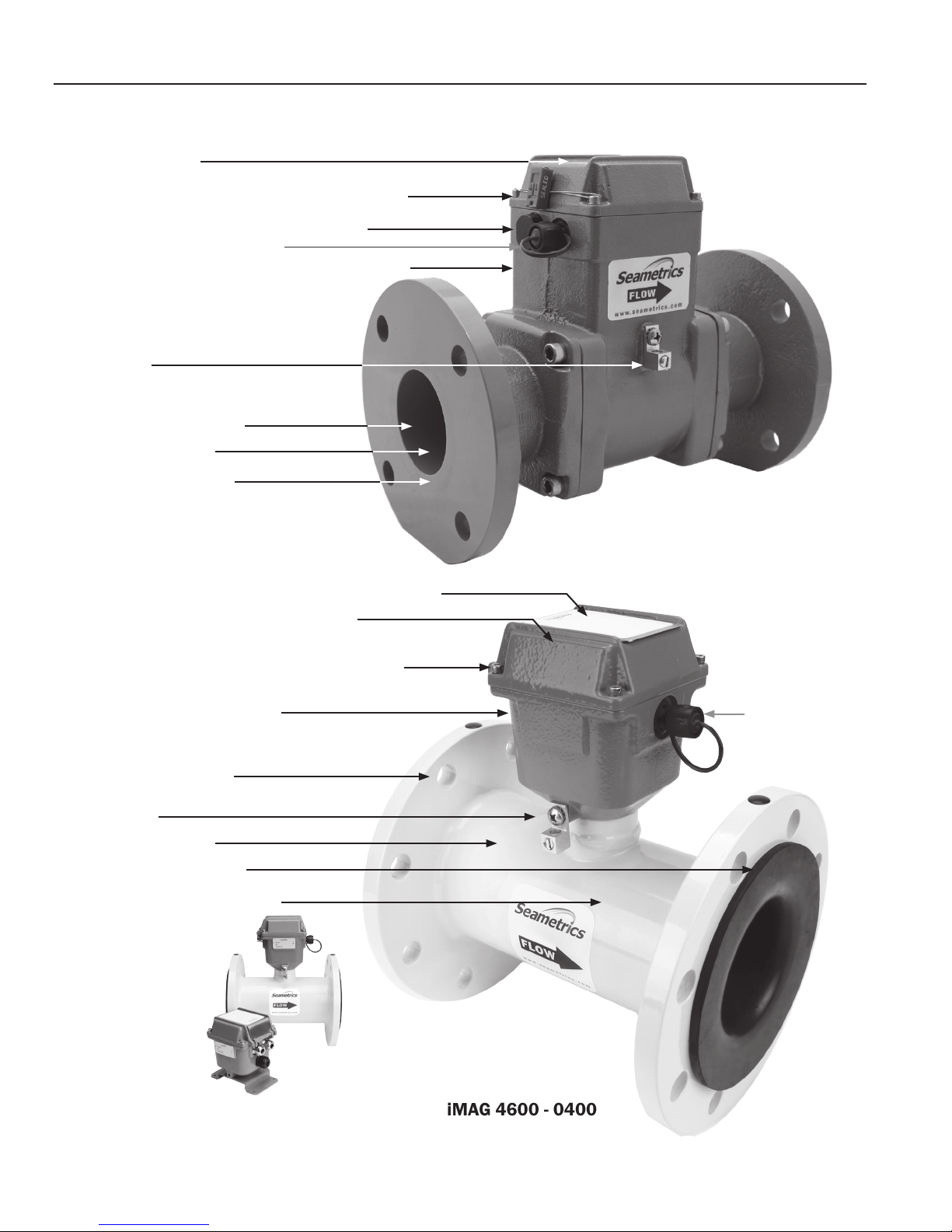
FEATURES
Conguration Port (For Factory Use Only)
the user. Bi-directional ow is standard. Forward, reverse and
net ow can be read from the display. If forward and reverse
ow data needs to be sent to another device, Modbus output
is required.
The iMAG 3600 and 4600 can be externally powered with 9-36
Vdc at 30 mA average. The 4600 is also available in a battery
powered version.
The standard 20-foot (6 meter) cable also provides outputs for
use with a variety of Seametrics and other displays and controls
for remote reading, data logging and telemetry applications.
4-20mA passive current loop and high frequency outputs
are optional on the externally powered models. Pulse output
is standard on the battery powered model. The iMAG 3600
remote display meter can be supplied with an optional internal
AC power supply.
Multifunction Display
Light Sensor Keypad
Protective Cover with Magnetic Seal
Page 1
GENERAL INFORMATION
FEATURES Continued
Rate and total indicator
Security seal & cross-drilled screws (2) for tamper-evidence
Power and Output cable port access, tamper-sealed
Conguration Port (For Factory Use Only)
Powder-coated ductile cast iron body & electronics housing
Equalization lug
Glass lled molded plastic liner
316SS electrodes (Inside)
Flanges, 150 lb. ANSI pattern
Rate and total indicator with protective cover and keypad sensors
Powder-coated ductile cast iron electronics housing
Security seal & cross-drilled screws (2) for tamper-evidence
Power and Output cable port access
Flanges, 150 lb. ANSI pattern
Equalization lug
316SS electrodes (Inside)
Santoprene/Polypropylene Liner
Welded steel epoxy-coated ow tube
iMAG 4600 - 300
Conguration Port
(For Factory Use Only)
iMAG 3600-0400
(Remote indicator)
Page 2
iMAG 4600 - 0400
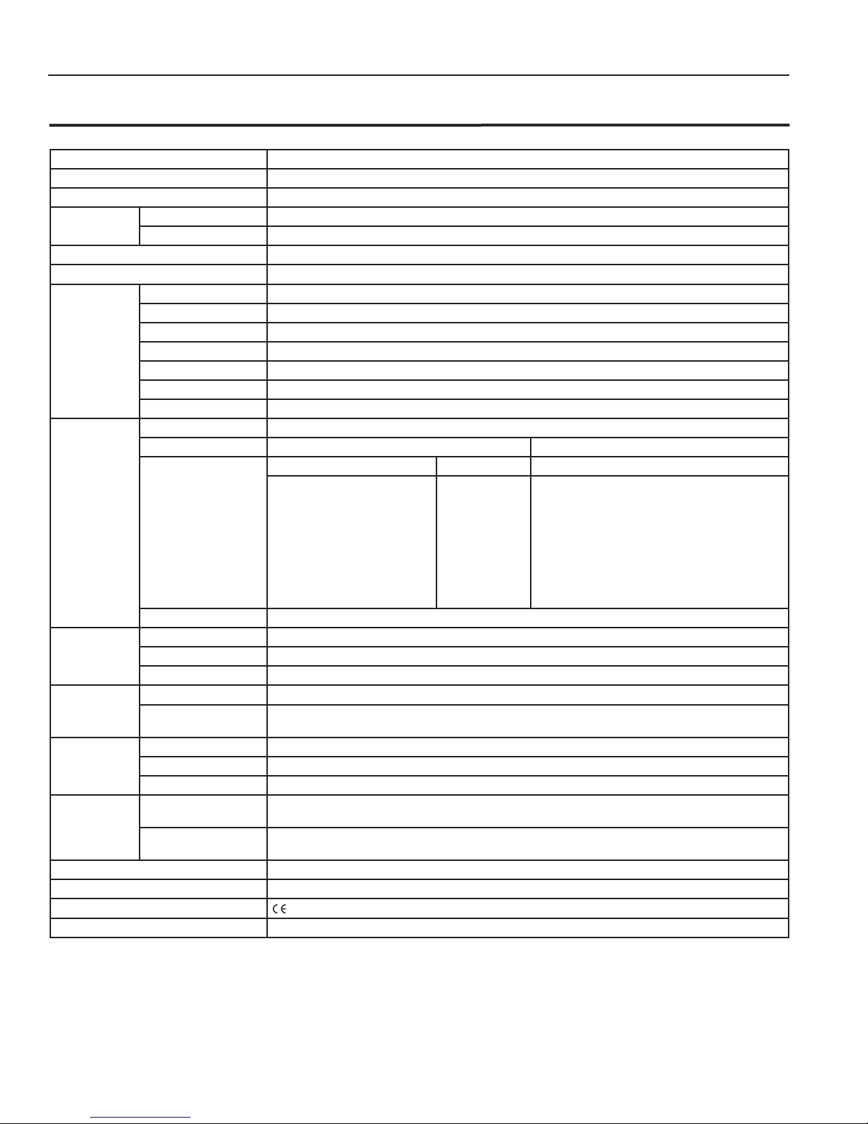
SPECIFICATIONS
SPECIFICATIONS*
Pipe Sizes 3”,4”, 6”, 8”, 10”, 12”
Flanges 150 lb. ANSI pattern
Pressure 150 psi (10.3 bar) working pressure
Temperature Operating 10˚ to 130˚ F (-12˚ to 54˚ C)
Storage -40˚ to 158˚ F (-40˚ to 70˚ C)
Accuracy +/- 1% of reading +/- 0.025% of full-scale ow from low ow cutoff to maximum ow rate of 10 m/sec
Low Flow Cutoff 0.5% of maximum ow rate
Materials Body (3” Only) Ductile cast iron, powder-coated
Body (4”-12”) Welded steel, epoxy-coated
Liner (3” Only) Noryl®
Liner (4”-12”) Santoprene/Polypropylene
Electronics Housing Ductile cast iron, powder-coated
Electrodes 316 stainless steel
O-ring (3” Only)
Display Type 128x64 dot-matrix LCD
Digits 5 Digit Rate 8 Digit Total
Units
Please Note:
All iMAG meters are factory set
for gallons per minute (GPM)
rate and gallons total. If other
units are required, they can be
programmed in the eld.
Bi-directional
1
Power DC Power 9-36 Vdc @ 250 mA max, 30 mA average
2
3
Pulse Frequency
Output
AC Power
Battery
Signal Current sinking pulse, isolated, 36 Vdc at 10 mA max
Pulse Rates User-scalable from 0.1 to 99,999.9 volume units/pulse. Pulse width is one-half of pulse period with
Options 4-20mA Current Loop Isolated, passive, 24Vdc, error less than +/- 0.1% of pulse/frequency output
Digital Output Isolated, open collector, 24 Vdc, 650 Ω maximum loop resistance
Serial Communications Isolated, asynchronous serial RS485 (Recongurable for RS232 or 3.3V CMOS), Modbus RTU protocol
Cable Control Cable Six-conductor water-blocked cable, polyurethane jacket, 20ft (6m) standard length for power, pulse
Remote Display Cable
(iMAG 3600)
Conductivity >20 microSiemens/cm
Empty Pipe Detection Hardware/software, conductivity-based
Regulatory
Environmental IP68 to 10ft (3m) depth
EPDM
Rate Volume Units Rate Time Units Total Volume Units
Gallons
Liters
Barrels (42 gallon)
Cubic Feet
Cubic Meters
Million Gallons
Mega Liters
Imperial Gallons
Million Imperial Gallons
Second
Minute
Hour
Day
Gallons
Gallons x 1000
Million Gallons
Liters
Kilo Liters
Mega Liters
Barrels (42 gallon)
Cubic Meters
Cubic Meters x 1000
Cubic Feet
Cubic Feet x 1000
Million Cubic Feet
Imperial Gallons
Imperial Gallons x 1000
Million Imperial Gallons
Forward Total, Reverse Total, Net Total
85-264Vac, 50/60Hz, 0.12A
Two lithium 3.6V ‘D’ batteries, replaceable. See chart on page 11 for battery life expectancy.
minimum pulse width of 2.5 ms, 200 pulses/sec max, 10 pulses/sec max battery option
frequency or optional outputs (optional lengths up to 100’ available)
33ft (10m) standard length (optional lengths up to 100’ available)
(EN 61326) pending, NSF-61 on 3” ONLY
*Specications subject to change. Please consult our website for the most current data (www.seametrics.com).
1
If forward and reverse ow data needs to be sent to another device, either the -ADDX, -DDDX or Modbus output is required.
2
iMAG3600 only, iMAG4600 requires external AC power supply
3
iMAG4600 only
Page 3
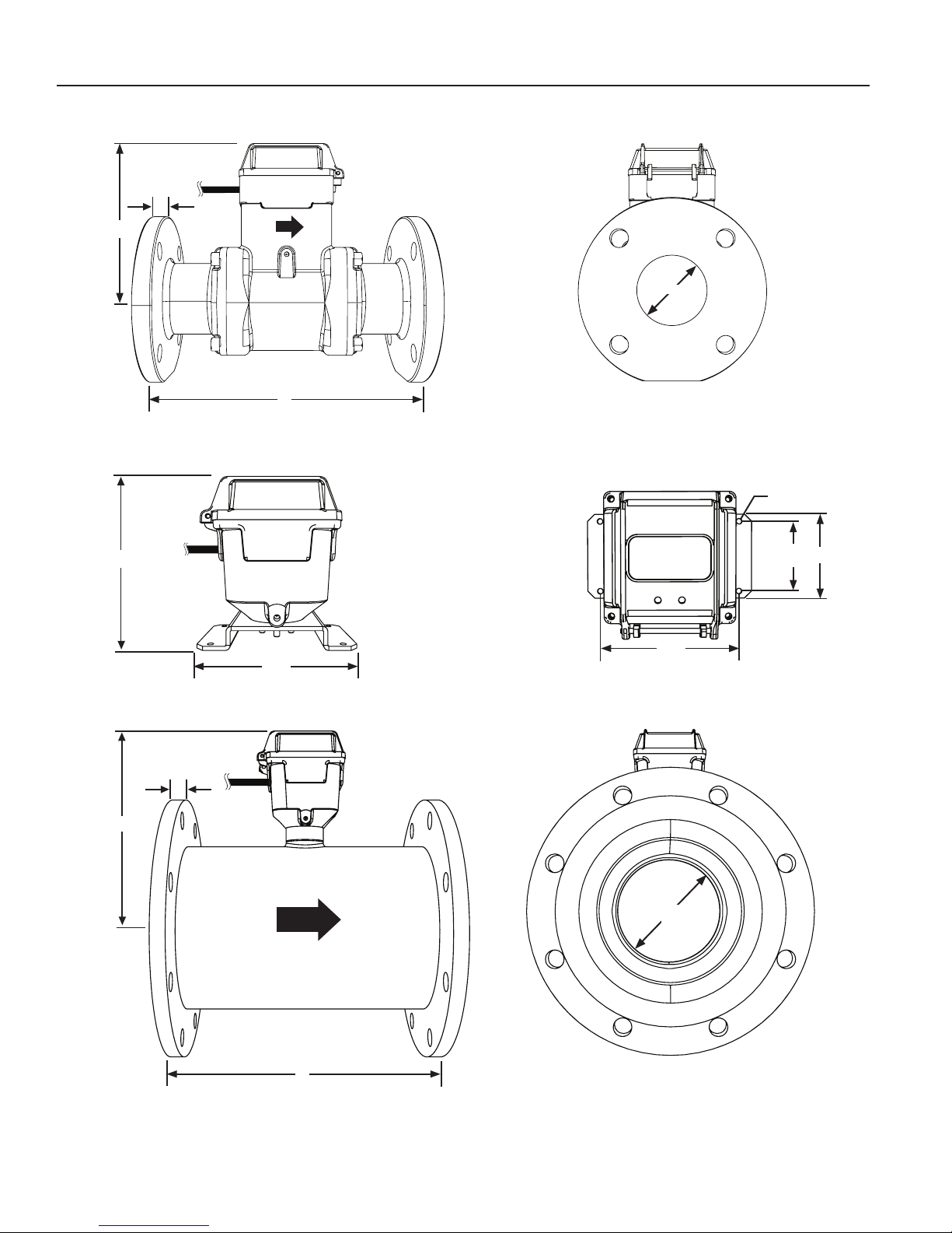
SPECIFICATIONS
DIMENSIONS
H
Cable Exit
T
(Metal Flange)
L
(Including Rubber Gaskets)
iMAG4600 - 0300 Shown
ID
iMAG3600 Remote Shown
.20” Dia.
5.62”
H
Cable Exit
T
(Metal
Flange)
Cable Exit
5.27”
iMAG4600 - 0400 to 1200
Shown
4.38”
ID
2.5”
3”
L
(Including Rubber Gaskets)
Page 4
 Loading...