


FT500-Series
FLOW COMPUTER
INSTRUCTIONS
• FT520
• FT522
F T 5 0 0 - S E R I E S F L O W C O M P U T E R I N S T R U C T I O N S

Page 1
GENERAL INFORMATION, FEATURES, DIMENSIONS, SPECIFICATIONS
FEATURES
Setting Keys
Cover Screws*
Indicator Lights
The FT500-Series is a batching flow processor with additional
output controls. It is designed for use with Seametrics flow
meters and flow sensors, as well as other manufactuer’s
products which have frequency output proportional to flow.
In addition to batch functions, the FT500-Series indicates
flow rate, and other data in large 3/8” (9.66 mm) digits on
an easily-read, backlit display. Units of measure are user
selectable, and range from milliliters per second to millions
of gallons per day. The unit can be 110 Vac powered with a
standard 3-wire cord (included), 220 Vac powered (optional),
or DC powered through an internal terminal strip (battery not
included).
An analog output of 4-20 mA is available both in active and
passive loop configuration, and in 0-5 Vdc or 0-10 Vdc outputs,
and can be used in applications such as flow rate logging. Two
programmable pulse scaled outputs are also standard, and
can be used, for example, to provide proportional chemical
feed with a pulse-responsive metering pump.
The housing is supplied with two brackets for wall-mount
applications, or the top/bottom housings can be easily
separated and reassembled for panel-mount.
*Can be ordered cross-drilled for seal wire
Display
115 Vac, 50/60 Hz @ 125 mA, (220 Vac optional), 12 Vdc @ 750 mA
32˚ - 130˚ F (0˚ - 55˚ C)
Precision cast aluminum, NEMA 4X, panel or wall mount configuration
Two form C (SPDT) relays, 115 Vac 6A max
100 mA at 60 Vac/Vdc, opto-isolated, open-collector
Non-volatile EEPROM with auto-backup
12 Vdc, 10 mA
Totalizer = 8 digit Rate = 5 digit, backlit
Volume = Gallons, cubic feet, cubic meters, millions of gallons, milliliters, fluid ounces, pounds, liters
Time = Seconds, minutes, hours, days
4-20 mA passive opto-isolated; 4-20 mA active; 0-5 Vdc, or 0-10 Vdc
1-1000 Hz, ESD protected, interfaces to current sinking sensor output
NEMA 4X
Non-volatile EEPROM, auto-backup
Power
Temperature
Enclosure
Batch Outputs
Max Pulse Output
Memory Type
Sensor Power
Display
Units
Analog Output
Sensor Input
Environmental
Setup Memory
SPECIFICATIONS*
*Specifications subject to change • Please consult our website for current data (www.seametrics.com).
6.42"
6.42"
1/2" NPT
5.67"
DIMENSIONS
4.65"
1/2" NPT
5.67"
•
•
SEN1
–G
SEN2
Alternate
DC power
Customer Supplies
1A Fuse
Pulse 1
Pulse 2
Pulse Outputs
(for metering pumps)
Regeneration Outputs
AC Power
Relay 1
Relay 2
Main power fuse
250mA
Line
Neutral
Ground
Ribbon connector
from display board
Resume
Start/Stop
Remote
Controls
NO
COM
NC
NO
COM
NC
Resume
COM
BATCH
+12
Power
Signal
Ground
RED
WHITE
BLACK
Meter
Dry contact
0-5 V or
0-10 V or
4-20 mA
Analog Switch*
Analog Header
A
+
-
B
Active
Passive
Jumpers
A
P
5V
10V
4-20mA
An Output
110 Vac
Jumpers
220 Vac
Jumper
*Consult Seametrics before
changing from factory pr eset
Batch Control Connection (if used). Connect the valve or
other device(s) to be controlled for star ting and stopping the
batch to the appropriate relay terminals. Note: if the staged
shutoff (“prewarn”) will not be used, connect to relay one
only. Relay 1 remains energized for the entire batch cycle. If
a staged shutoff is desired, connect the main valve to Relay
2 (early shutoff) and the low-flow valve to Relay 1.
Monitor Alarm Connection (if used). Connect the alarm
devices to the appropriate relay terminals. Note that the
relays have both normally-open (NO) and normally-closed
(NC) contacts.
Analog Connection (if used). This output can be configured
4-20 mA, 0-5 V or 0-10 V by placing a jumper in the correct
position on the analog header. The analog switch next to
the header selects active (powered) or passive (unpowered)
output. NOTE: Consult factory to change internal firmware
when changing switch position. When using the 12 Vdc
powered input you may only select passive output.
Power Connection. Connect AC or DC power as desired
to the appropriate terminals. For safety, if using AC power,
be sure to connect the ground terminal provided to a good
earth ground. If using 12 Vdc, use a 12 Vdc 500 mA power
supply. Replace the front panel, taking care to reconnect
the ribbon cable if it has been disconnected. When power
is switched on, the display should light up immediately with
meaningful letters or digits.
5.50"
gasket
PANEL
CUTOUT
5.50"
6.03"
6.03"
1/4" holes (4 required)
.375"
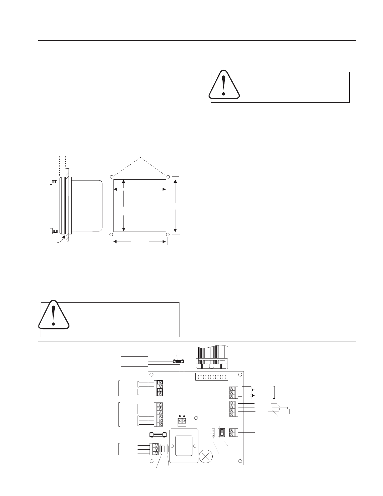
INSTALLATION, REPAIR, CONNECTIONS
Page 2
Caution: Always disconnect power to the
unit before opening the teminal cover. Do
not reconnect power until all connections
have been made and the teminal cover has
been replaced.
PANEL CUT-OUT
Wall Mounting. Using the four screws provided, attach
the two foot brackets to the sides of the enclosure. Then
attach the unit to any secure surface by inserting screws
through the mounting holes in the foot brackets.
Panel Mounting. Follow the dimensions given for “Panel
Cutout”. Be sure to include the four corner screw holes.
After cutting and drilling, place the front plate on the front
side of the panel with its gasket against the panel, and the
remainder of the square housing on the back side. Slide
the screws through the four holes drilled in the panel, and
into the threaded holes in the housing. Tighten until the
gasket is firmly compressed against the panel.
Expose Terminals. Remove the four screws which hold the
front plate to the lower housing flange. Remove front plate.
The display board is attached to this front plate. It is also
connected to the power board by a ribbon cable. This cable
can be disconnected while making connections. Connections
can be made inside the enclosure, or the terminals can be
unplugged by gentle tugging for easier access.
Caution: When the control is powered up, relay or analog outputs may be present. If this
could be a hazard, wait to make external connections until programming is complete.
Repair
The only field-repairable component on the FT520 is the
fuse. If failure is due to a cause other than a blown fuse,
it is necessary to replace the entire board stack. Contact
your distributor for information.
Connections
Sensor Connection. Follow the “Connections” diagram to
connect either two or three wires from the flow meter or
flow sensor.
 Loading...