


d
C
FT430/440/450
Rate/Total Indicator
Instructions
o
m
e
i
p
f
PROUDLY
MADE
IN THE
USA
i
t
r
e
C
ISO
9001:2008
a
n
y
Optional Protective Cover Closed

TABLE OF CONTENTS
General Information
General Information ...................................................................................................................................................Page 3
Specications ................................................................................................................................................................Page 3
Features ...........................................................................................................................................................................Page 4
Pulse Output Functions .............................................................................................................................................Page 4
Installation
Wall Mount .....................................................................................................................................................................Page 5
Meter Mount .................................................................................................................................................................Page 5
Panel Mount ..................................................................................................................................................................Page 5
Connection Diagrams
FT450 Standard .............................................................................................................................................................Page 6
FT430/3-Wire Mechanical Meter ...........................................................................................................................Page 6
Connections for FT430-139 or FT440-139 —115Vac Option ......................................................................Page 7
FT440/3-wire Mechanical/Dual Scaled Pulse Output ....................................................................................Page 7
FT440/EX Magmeter ...................................................................................................................................................Page 8
FT440-139/EX Magmeter .........................................................................................................................................Page 8
Settings
K-Factor ...........................................................................................................................................................................Page 9
Changing Flow Indicator Settings .........................................................................................................................Page 9
Menu Navigation .........................................................................................................................................................Page 9
FT440 Secondary Menu Functions .......................................................................................................................Page 11
FT430/440/450 INSTRUCTIONS
Troubleshooting
Problems .........................................................................................................................................................................Back
Probable Causes ...........................................................................................................................................................Back
Things to Try ..................................................................................................................................................................Back
Seametrics • 253.872.0284 Page 2 seametrics.com

GENERAL INFORMATION
FT430/440/450 INSTRUCTIONS
The FT430/440/450 ow computers are microcontroller-
based indicator/transmitters that interface with pulse
output ow sensors to compute and display ow rate, ow
total, and also generate output signals representing ow.
The FT430 and FT450 have one scaled pulse output and
one pulse pass through. The FT440 has two scaled pulse
Pulse and 4-20mA analog outputs can be used to signal
external devices, e.g. certain metering pumps and water
treatment controls. Alternatively, one or more pulse
outputs can be congured as alarm outputs. These ow
computers can be password protected to prevent resetting
the total or changing conguration settings.
outputs. Galvanic isolation is provided for most pulse
outputs.
The FT430/440/450 meters are available in wall and meter
mount congurations. The FT430 and FT440 models
The FT450 is battery powered while the FT430 may be
powered by an external DC power source or an optional
internal AC power supply*. The FT440 is a “two-wire” or
can also be panel mounted. Some congurations can
be converted from wall to meter or meter to wall after
installation if needed. Consult factory for details.
“loop powered” device, meaning that it is powered by the
4-20 mA loop circuit itself. An optional internal AC power
supply* is available for the FT440 with dual 24 and 12VDC
outputs to power both the loop and sensors requiring
more power than the loop can supply.
Order the FT440 only if a 4-20mA output signal is a
requirement and the FT450 if internal battery power is
needed. Otherwise the FT430 offers the most exibility.
*Internal power supply is available for the wall mount option only.
Specications*
FT440 FT450FT430
Power
Display
Units Rate Units
Outputs Pulse Output 1 Scaled pulse output, high alarm output or low alarm output. Optoisolated on FT430 and FT440.
Set P Range 0.1 - 99999.9 units/pulse 0.1 - 99999.9 units/pulse 0.1 - 99999.9 units/pulse
Input 5V pulse or contact closure 5V pulse or contact closure
Input Range 0.75
K-Factor Range .001 - 999999.999 .001 - 999999.999 .001 - 999999.999
Flow Alarm Output
Range
Operating Temperature 0˚ to 55˚ C (-32˚ to 131˚ F) 0˚ to 55˚ C (-32˚ to 131˚ F) 0˚ to 55˚ C (-32˚ to 131˚ F)
Non-Operating
Temperature
Environmental NEMA 4X, IP67 NEMA 4X, IP67 NEMA 4X, IP67
Regulatory
Rate 5-digit autorange 5-digit autorange 5-digit autorange
Total 8-digit 8-digit 8-digit
Total Units
Pulse Output 2 Pulse pass through
Loop Power
Output
7-30Vdc, 4mA
Gallons/Second/Minute/Hour/Day, Liter/Second/Minute/Hour/Day, Cubic Feet/Second/Minute/Hour/Day, Cubic Meters/
Second/Minute/Hour/Day, Miner’s Inch, Mega Liters/Day, Million Gallons/Day, Fluid Oz/Second/Minute/Hour/Day
Gallon, Gallon x 1000, Liters, Mega Liter, Cubic Meter, Acre Feet, Cubic Feet,
Cubic Feet x 1000, Million Gallon, Miner’s Inch Day, Acre Inch, Fluid Ounce
N/A 4-20mA Loop N/A
2
- 2000Hz 0.752 - 2000Hz 0.752 - 550Hz
0.1 - 99999.9 0.1 - 99999.9 0.1 - 99999.9
-40˚ to 75˚ C (-40˚ to 158˚ F) -40˚ to 75˚ C (-40˚ to 158˚ F) -40˚ to 75˚ C (-40˚ to 158˚ F)
Mark Mark Mark
7-30Vdc, 4mA (4-20 mA when
loop-powered)
Scaled pulse output, high alarm
output or low alarm output.
1
Lithium “C”, 3.6Vdc, replaceable. Life is
~5 years depending on usage.
1
Pulse pass through
Micropower GMR Sensor
(square wave)
* Specications subject to change • Please consult our website for current data (www.seametrics.com).
1 Scaled output pulses have a xed width of 100ms. Maximum pulses per second is 6.5Hz
2 For pulse frequencies <1 Hz, increase setting in SET F menu to 3 or higher.
Seametrics • 253.872.0284 Page 3 seametrics.com
GENERAL INFORMATION
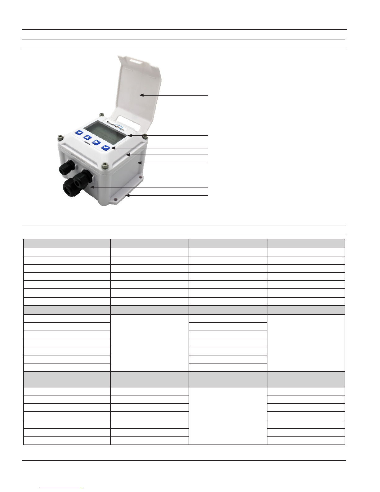
Features
FT430/440/450 INSTRUCTIONS
Protective Cover (Optional)
Display
Setup Keys*
Electronics Module
Lower Housing
Cable Gland Strain Relief
Wall-Mount Brackets
* Includes password protection for tamper
prevention when needed
Pulse Output Function Table
PULSE OUTPUT 1 (SCALED) FT430 FT440 FT450
TYPE Current sinking Current sinking Current sinking
MAX. VOLTAGE 45 Vdc 45 Vdc 3.6 V
MAX. CURRENT 100 mA 100 mA 100 mA
MAX. FREQUENCY 6.5 Hz 6.5 Hz 6.5 Hz
PULSE WIDTH 100 ms 100 ms 100 ms
ISOLATION 300 V 300 V
CONFIGURABLE AS ALARM YES (High or Low) YES (High or Low) YES (High or Low)
PULSE OUTPUT 2 (SCALED) FT430 FT440 (Note 2) FT450
TYPE
MAX. VOLTAGE 45 Vdc
MAX. CURRENT 100 mA
MAX. FREQUENCY 6.5 Hz
PULSE WIDTH 100 ms
ISOLATION 300 V
CONFIGURABLE AS ALARM YES (High or Low)
PULSE OUTPUT 2 (PASS-
Not Available
FT430 FT440 FT450
Current sinking
THROUGH)
TYPE Current sinking
MAX. VOLTAGE 45 Vdc 3.6 V
MAX. CURRENT 10 mA 100 mA
MAX. FREQUENCY
PULSE WIDTH SAME AS SENSOR INPUT SAME AS SENSOR INPUT
ISOLATION 300 V
CONFIGURABLE AS ALARM NO NO
NOTE 1: 150 V effective isolation when using Seametrics micropower sensors. • NOTE 2: With 2000 ohm or lower pull-up resistance.
2000 Hz
NOTE 2
Not Available
NOTE 1
Not Available
Current sinking
550 Hz
NOTE 1
Seametrics • 253.872.0284 Page 4 seametrics.com

INSTALLATION
3.374
4.77 (121.2)
(110)
#10
.10"
.50"
FT430/440/450 INSTRUCTIONS
Screw
4.10 (104.1)
4.35 (110.5)
2.50
(63.5)
4.10
(104.1)
#10
Screw
0.10 (2.5)
0.78
.78"
(19.8)
4.33
Dimensions are in Inches (Millimeters)
Wall Mount. To mount an FT430/440/450 indicator to
the wall, hold the unit in the desired position, mark the
holes in the mounting feet, drill and mount with screws.
A meter-mounted indicator can be converted to a wall
mount using an adapter mounting kit. Contact distributor
for information.
Meter Mount. If the FT430/440/450 indicator was ordered
as a meter mount model, the housing is already mounted
directly to the ow sensor and needs no further installation.
An FT430/440 module can be converted from a wall-
mount to a meter-mount using the mounting kit (contact
distributor) that includes a lower housing and associated
hardware and installs as follows:
0.50
(12.7)
3.37
(85.6)
Meter Mount
Sensor Wires
Sensor Wires
Panel Mount. Using the “Panel Cutout” drawing as a guide,
cut a hole in the panel. Place the FT430/440 indicator on
the panel and mark the holes, drill, and mount with the
supplied screws and washers.
3.56 (90.4)
1. Remove the strain relief through which the ow
sensor cable runs.
2. Cut the cable to about 6” in length. Carefully strip
the cable jacket to expose the three colored wires
(red, white, and black) inside.
3. Route the wires through the threaded connector
pre-installed in the bottom of the housing.
4. Start the threaded connector into the female thread
on the top of the ow sensor. Be sure to match the
oblong shape on the bottom of the housing to the
depression on the top of the ow sensor.
5. Using an ordinary screwdriver inserted in one side
of the slot (see drawing), tighten the screw as much
as possible.
6. Strip the wire ends, make the connections to the
indicator as shown in Connections Diagrams, and
then use the cover screws to attach the indicator to
the top of the housing.
Seametrics • 253.872.0284 Page 5 seametrics.com
Panel Cutout
2.4 (61) TYP
3.5 (88.9) TYP
(PANEL CUTOUT)
3.56
(90.4)
.218 (5.5)
Connections. To connect the ow computer to a ow
sensor or an external device such as a chemical metering
pump, follow the Standard Connections diagrams on the
following pages.

CONNECTION DIAGRAMS
Sensor
FT450 Standard Connections
FT430/440/450 INSTRUCTIONS
Caution: Do not apply
external power to the FT450.
BLACK
WHITE
RED
Micropower
Flow Sensor
POWER
SENSOR
S
_
+
_
+
ENGD
FT450
Pulse
Pass-thru
Lithium C,
3Vdc
Replaceable
_
S
+
Battery
_
PULSE
OUT 2
_
+
+
_
PULSE
OUT 1
_
+
+
Pulse Responsive
Metering Pump
Current Sinking
Polarity-Sensitive
Connections for FT430/3-Wire Mechanical Meter
POWER
_
SENSOR
S
_
+
ENGD
_
+
+
_
S
+
_
7-45Vdc
+
Supply
BLACK
WHITE
RED
FT430
Pulse
Pass-thru
_
PULSE
OUT 2
_
+
+
_
PULSE
OUT 1
_
+
+
Pulse Responsive
Metering Pump
Flow
Seametrics • 253.872.0284 Page 6 seametrics.com

CONNECTION DIAGRAMS
Power Source
POWER
SENSOR
ENGD
+
_
_
+
S
PULSE
OUT 2
PULSE
OUT 1
+
_
+
_
RED
WHITE
BLACK
+
_
9-30 Vdc
Loop Power
Supply
Flow
Sensor
FT440
Electronic
Metering Pumps
_
+
S
_
+
_
+
_
+
4-20mA
Device
+
_
Connections for FT430-139 or FT440-139 —115Vac Option
4-20mA
+
Device
Dashed line shows (-) terminal connection
if 4-20mA device is not used (e.g. FT430)
FT430/440/450 INSTRUCTIONS
12V
_
Device
_
+
POWER
_
_
+
+
ENGD
_
SENSOR
S
+
FT430/FT440
_
PULSE
OUT 2
+
PULSE
OUT 1
_
+
L
N
G
FT430-139
FT440-139
(Dual Power Supply)
Lower Housing
Connections for FT440/3-wire Mechanical/ Dual Scaled Pulse Out
BLACK
WHITE
GREEN
_
24Vdc
+
To 115Vac
12Vdc
_
+
Seametrics • 253.872.0284 Page 7 seametrics.com

CONNECTION DIAGRAMS
Red
Connections for FT440/EX Magmeter
FT430/440/450 INSTRUCTIONS
+
4-20mA
_
Device
Status
Zero
Adj
LED
Option
1
Reverse
-
Output
Only
+
2
Max 6mA
30Vdc
12-24Vdc
Output
Power
Forward
3
-
+
4
5
-
+
6
_
+
_
+
White
Green
Black
Red
Connections for FT440-139/EX Magmeter
Black
_
9-30 Vdc
Power Supply
+
_
12 Vdc
Power Supply
+
Red
FT440
POWER
_
_
+
+
SENSOR
S
ENGD
_
+
_
S
_
S
_
PULSE
OUT 2
+
PULSE
OUT 1
_
+
_
L
N
G
FT440-139
(Dual Power Supply)
Lower Housing
BLACK
WHITE
GREEN
_
24Vdc
+
12Vdc
To 115Vac
Power Source
_
_
+
+
Zero
Adj
Reverse
-
Output
+
Max 6mA
30Vdc
Forward
Output
-
+
12-24Vdc
-
Power
+
EX Magmeter
4-20mA
+
Device
Status
LED
Option
1
Only
2
3
4
5
6
_
+
_
+
Dashed line shows (-) terminal connection
if 4-20mA device is not used
POWER
_
_
+
+
White
Green
Black
Red
SENSOR
ENGD
_
_
S
s
+
_
PULSE
OUT 2
+
PULSE
OUT 1
_
+
FT440
Seametrics • 253.872.0284 Page 8 seametrics.com

0.00
0
SETTINGS
10031295
MF81T-P200
K: 53.6
FT430/440/450 INSTRUCTIONS
K-Factor
At a minimum, every FT430/440/450 ow computer must
be programmed with the “K-factor”. (This is the number of
pulses that the meter produces per gallon of ow.) If you
wish to read in units other than gallons, see below.
The K-factor on any Seametrics ow sensor tting or in-
line meter can be found on the model-serial label. The
line reading K = xxxx gives the desired number. For depth-
adjustable sensors (110, 210, 150, 250 models), use the
calculator on our website.
Fixed Depth Meter
Find Your K-Factor Here
Menu Navigation
The left/right keys are used to move through the menus
and position the cursor during data entry. The up arrow is
used to scroll through the available values that are to be
entered. (examples: numerical values for K factor entry or
selection of units from the available options) The enter key
(represented on the keypad by the check mark) is used to
save selected entries and in conjunction with the exit tab to
move between menu screens. As one navigates the menus
the current parameter setting is shown and instructions are
displayed for how to change the selected parameter.
MAIN MENU
R UNITSET K T UNIT SET D
086238.235
PRESS TO SET NUMBER
OF PULSES RECEIVED PER
GALLON OF FLOW
SET P RESET EXIT
All menu screens consist of two rows of tabs surrounding a
dialog box that lets you view and change setup parameters.
Changing Flow Indicator Settings
THE HOME SCREEN
GPD
MID
The HOME Screen, shown above, is the normal screen
which displays TOTAL ow volume and ow RATE. The Four
buttons below the LCD display are used to access menu
screens for viewing and changing setup parameters.
SET K
R UNITSET K T UNIT SET D
086238.235
PRESS TO SET NUMBER
OF PULSES RECEIVED PER
GALLON OF FLOW
SET P RESET EXIT
View or change the K factor. The K factor is the number of
pulses the ow sensor provides for every gallon of ow.
(Note that the decimal is xed at three places. If you only
have two decimal places for your K-factor, enter a zero for
the third digit. If unable to set K-factor, the unit is "locked"
to prevent tampering. Please contact your distributor for
assistance.)
R UNIT
R UNITSET K T UNIT SET D
FLOW RATE = GPD
PRESS TO SET UNITS
FOR DISPLAY
Seametrics • 253.872.0284 Page 9 seametrics.com
SET P RESET EXIT
View or change the ow rate units

SETTINGS
FT430/440/450 INSTRUCTIONS
T UNIT
R UNITSET K T UNIT SET D
TOTAL = GALLONS
PRESS TO SET UNITS
FOR DISPLAY
SET P RESET EXIT
View or change the total volume units
SET D
R UNITSET K T UNIT SET D
000
PRESS TO CHOOSE
NUMBER OF DECIMAL PLACES
IN TOTAL DISPLAY
SET P RESET EXIT
View or change the number of decimals displayed in the
total volume display
SET P OR SET A
R UNITSET K T UNIT SET D
00000.0 GALLONS
PRESS TO SET NUMBER OF
GALLONS TOTALIZED PER
PULSE SENT OUT PULSE1
RESET
R UNITSET K T UNIT SET D
PRESS TO RESET TOTAL
SET P RESET EXIT
Reset the total ow volume to zero. This tab is not available
when the -64 non resettable total option is ordered
EXIT
R UNITSET K T UNIT SET D
PRESS TO EXIT MENU AND
RETURN TO FLOW DISPLAY
SET P RESET EXIT
Return to the home screen, enter a submenu, or accept a
parameter change
The Exit menu also allows access to the secondary menu,
as described on the next page.
SET P RESET EXIT
The factory setting will show Set P which allows one to
view or change the volume of ow totalized per pulse sent
to pulse out 1. The units for Set P follow the units selected
for the rate display. (With EXIT highlighted, pressing the
up arrow four times will allow pulse out 1 to be an alarm.
The alarm can be set to trigger on either a high or low ow
condition as determined by the user.)
SET 20 (FT440 ONLY)
R UNITSET K T UNIT SET D
00000.0 GALLONS
PRESS TO SET THE FLOW
RATE AT WHICH 20 mA
(MAX) OUTPUT IS DESIRED
SET P RESET EXIT
Input the ow rate at which 20 mA (max) output is desired
SET 20
NOTE: To conserve battery life on battery
powered units, the display screen goes
into sleep mode (black screen) after
approximately 3 minutes of non-use. Push
any button to reactivate display.
Seametrics • 253.872.0284 Page 10 seametrics.com

SETTINGS
The FT440 Secondary Menu Functions
FT430/440/450 INSTRUCTIONS
When using the FT440, a secondary menu is available with
further options. Enter the secondary menu by pressing the
up arrow four times while EXIT is highlighted.
OUTPMAIN INPP CODE
SCROLL TO SELECT A
SUBMENU AND CHANGE
FEATURES
EXIT
OUTP
OUTPMAIN INPP CODE
PRESS TO SET ALARMS,
PULSE OUT, AND 4-20 mA
EXIT
View or change the function of Set P tab on the main menu.
INP
OUTPMAIN INP P CODE
PRESS TO SET F, J, REED
AND PULSE INDICATOR
EXIT
View or change the lter (set F), jitter (set J), enable reed
mode. Use the lter setting if the display is jumping
excessively due to ow conditions. Use the jitter setting to
enter a time delay to handle start up conditions. Jitter units
are seconds.
PCODE
OUTPMAIN INP P CODE
PRESS TO SET PASSCODE
AND CHANGE PROTECTED
FEATURES
EXIT
The P/A tab changes the function of the outputs. Default
is scaled pulse out for both outputs. Either output can be
changed to alarm high or alarm low. If alarm options are
selected menu tabs for setting the alarms will be displayed
on the main menu (alarm 1) or the secondary menu (alarm
2) If the alarm options are selected a Set H (hysteresis) tab
is available. The hysteresis entry is a % value. The value
denes the % change required for a change in alarm state
to occur.
The factory setting will show Set P2 which allows one to
view or change the volume of ow totalized per pulse
sent to pulse out 2. The units for Set P2 follow the units
selected for the rate display. If P2 is selected as an alarm
the menus will change to Set A2 and a Set H (hysteresis)
tab is available. The hysteresis entry is a % value. The value
denes the % change required for a change in alarm state
to occur.
Set 4 input the ow rate at which 4 mA (min) output is
desired.
ADJ L allows the adjustment of the 4 mA and 20 mA values
so that one can tune performance of the FT440 to match
the installed system values. The adjustment units range
from 0-32. Positive values adjust the setting incrementally
larger and negative values adjust the setting incrementally
lower.
Enter the pass code for access to protected features.
Protected Features
To enter the protected features use the left/right arrow
keys to navigate to the Pcode tab, found in the secondary
menu. Press the enter key and then enter the pass code.
The protected menu, shown below, will now be displayed.
The tabs have the following functions:
Set CD Enter a user created numerical pass code.
Lock Lock menu functions to prevent unauthorized
changes.
E/D R Disable or enable the total volume reset
function.
PCNT Keeps a running tally of the number of times
the pass code has been used.
Seametrics • 253.872.0284 Page 11 seametrics.com

TROUBLESHOOTING
Problem Probable Causes Things to try…
Display blank No power to the unit Check for minimum 12 Vdc at power terminals
Short in sensor circuit Disconnect sensor, see if display returns (zero ow
rate)
Battery dead or loose (FT450 only) Wiggle battery, replace if over three years old
Display is in sleep mode Push any button to reactivate display. (Display goes
to sleep after about 3 minutes of non-use.)
Display missing pixels Damaged display module Contact distributor for return/replacement
Display showing meaningless
characters
Display reads normally but ow
rate incorrect
Display reads normally but
incorrect pulse output
Display reads normally, but no
(or incorrect) 4-20mA output
(FT440 only)
Display reads zero when there
is ow
Unit's microcontroller crashed Disconnect and reconnect power. If problem
repeats, contact distributor for return/replacement.
Battery nearly dead Replace battery
Wrong K-factor or time base
Enter correct K-factor from meter, tting, or manual
entered
Wrong pulse output setting Use "Set P" to correct pulse output setting
Polarity reversed on pulse output
Reverse leads
terminals
Wrong 4mA setting or wrong 20mA
setting
Inadequate loop power supply
voltage
Polarity incorrect in 4-20mA loop
Use "Set 4" to correct target minimum ow rate.
Use "Set 20" to correct target top ow rate.
Check voltage (For 4-20mA applications, 24 Vdc is
recommended)
Compare to Connections diagram
circuit
Flow sensor failed Consult ow sensor manual for how to test
Break in ow sensor circuit Check for continuity with multimeter
Flow sensor not battery-compatible Check ow sensor model number for "micropower
option"
Display reads ow rate when
there is none
Long ow sensor wire, running
parallel to power wires
Flow sensor malfunction See ow sensor manual to check
Flow "jitter" (oscillating slosh) reads
as ow
Totalizer does not always
Break in power to meter The totalizer's memory is only updated every 15
appear to display the total ow
Seametrics • 19026 72nd Avenue South • Kent, Washington 98032 • USA
(P) 253.872.0284 • (F) 253.872.0285 • 1.800.975.8153 • seametrics.com
Reroute wire or change to shielded wire
Consult factory for "anti-jitter" setting
minutes. If power is lost, the totalizer will retain the
value last written but will not be updated to reect
any ow between the last write and the time the
power was lost.
LT-14235r2.3 20160912
9/12/16
 Loading...