

FT400 Flow Computer
DISCONTINUED
Instructions
SpecificationsGeneral Information
The SeaMetrics FT400 is a compact digital flow monitor
with user-programmed output features. Combined with
an IP Series insertion flow sensor or a WT turbine meter,
it is ideal for flow rate and total indication, chart recording, and proportional chemical feed. It is available in wall
or panel-mount enclosures, or in a round cast-aluminum
housing mounted directly on a SeaMetrics meter. For
wall-mounting, the non-metallic enclosure is splashproof
and has a clear cover. The housing for panel mounting
is standard 1/4 DIN-sized, with gasketed front panel and
membrane switches.
An eight-digit totalizer is resettable, unless ordered with
non-reset option. Programming prompts simplify set up
by indicating the next step. Pulse output is a programmable 0.1 second open-collector transistor pulse, which
is compatible with electronic metering pumps, PLC's,
computer input cards, and SeaMetrics controls. An optional 4-20 mA output feature is front-panel programmable in standard flow rate units.
Features
Power 11-28 VDC, 20mA max.
24-28 VDC
Flow Sensor Power 8 Volts DC, 50 mA maximum
Temperature 0° C to 70° C
Display Custom 8-digit LCD,
0.4" digits
Totalizer 8-digit resettable
(non-reset optional)
Rate Indication 8-digit with autorange
K Factor Range .050 - 1999.999
Pulse Output Range 0.1 - 99,999.9 gallons per
pulse
Pulse Output 0.1-second open-collector
transistor, 100 mA, 60 VDC
maximum
Analog Output
(Optional) 4-20 mA isolated 24 VDC, 500
Ohm maximum
Analog Output
Resolution 500 counts full scale
Sensor Output 100 mA, 60 VDC maximum
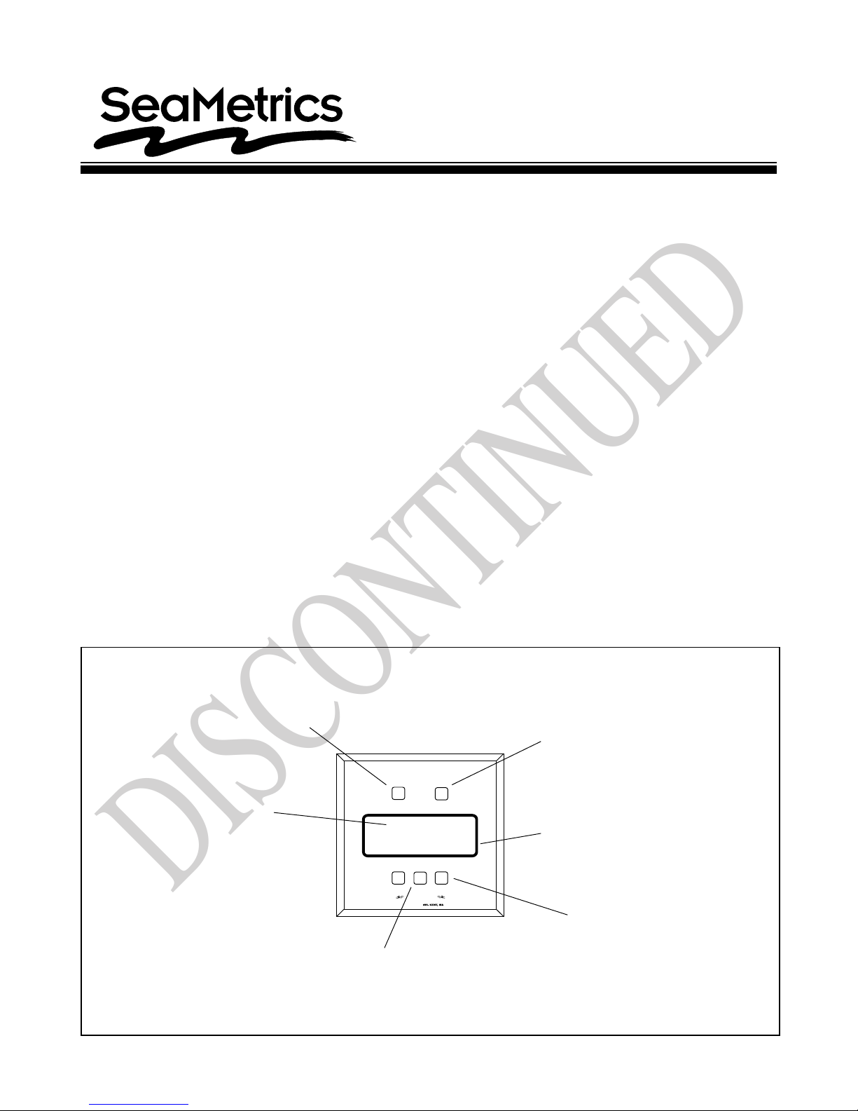
ResetTotalizertoZero
(Non-resettableoptional)
Promptsappear
whenprogram
buttonispushed.
"SETP"means
setpulseoutput
ingallonsper
pulse.
Otherprompts:
•SETK(meterfactor)
•SET20mA(optional)
•SETDP(totalizer)
FT400
RESET RATE/TOTAL
SETP
400.0
PROGRAM
Seaflow
-
+
Presstochange
settings:
•K-factor
•PulseOutput
•4-20mA(optional)
SwitchesbetweenRateand
TotalDisplays(Alsorespondsto
magnetoutsideenclosure)
Selectable
decimal
point
Buttonsincrease
ordecreasesetting
PUB -19081-1095
Page 1 0f 4

Installation
DISCONTINUED
FT400W: Wall Mounting. Four 3/16" screw holes are
located at the bottom of the front cover screw holes . Mark
the locations through the holes, then drill. Slip screws
down the holes and tighten.
FT400P: Panel Mounting. Use the dimensions on the
back page for making the panel cutout. Locate the dov etail mounting bracket groo v es on the side and the top of
the unit. After cutting out the panel, break an y sharp or
rough edges, then slip the panel gasket in place behind
the FT400 bezel and slide the unit through the panel
hole. Install the mounting brackets in their dovetail
grooves, with the slots of the clamping screws facing
out. Tighten the scre ws to pull the unit tightly against the
panel and compress the gasket slightly.
Connections
FT400M: This unit is pre-wired with 18 ft. of four-con-
ductor cable. See diagram for color coding of the leads.
If desired, the cable supplied can be removed, and connections can be made inside the unit, following the Connections diagram.
Standard Unit:
(+ )
Red
Black
Green
White
With Analog Option:
Red
Black (-) 12VDC to power supply
Blue (+ ) 4-20 mA
Orange
12VDC to power supply
(-) 12VDC to power supply
(+ ) pulse output
(-)
pulse output
(+ )
12VDC to power supply
(-) 4-20 mA
Sensor Out terminals are provided for passing on the
signal from a flow sensor to a second electronic device .
They do no need to be connected unless using such a
device.
FT400P: All of the instructions for the FT400W apply
except those regarding access to terminals. T o reach the
terminals, remove the four screws which hold the back
cover of the housing in place .
Analog Output Board. The optional 4-20 mA output
uses a third printed circuit board which plugs into the
terminal connection board. This board is pre-wired at the
factory with a jumper, so that powering the FT400
automatically provides power to the current loop. If an
isolated 4-20 mA output is required (see Connections) it
is necessary to remove the jumper and rewire as shown
in “Analog Output - Isolated”.
Programming
Caution: If pulse output is being
used to control an external device,
!
programming is completed. If malfunction or incorrect programming of the pulse output could
cause personal injury or property damage, separate safeguards must be installed to pre vent such
injury or damage.
Set K-Factor. To begin programming, press the PROGRAM key. The prompt SET K should appear. The Kfactor is the number of pulses per v olume unit. This number is provided with SeaMetrics meters, in pulses per
gallon. If the FT400 is to read in other units , the n umber
provided with the meter must be converted. The FT400
will then totalize in the selected units, and the rate reading will be in those units per minute. The rate is alwa ys in
units per minute. It is not possible to totalize in one unit
and read rate in units per hour or per second.
such as a metering pump, do not
connect the pulsed device until
FT400W: This unit is ordinarily supplied without prewiring. To reach the terminals, remove the front clear
cover, then remove the front panel. Turn the front panel
over, with the circuit boards still attached. Follow the
Connections diagram.
Note the polarity of the Pulse Output terminals. Be sure
to observe proper polarity when connecting to an electronic metering pump. If the pump does not respond to
the pulse output, try switching polarity.
2 of 4
To enter the K-factor, press the “+” or “-” keys until the
desired number is reached.
Set Pulse Output. Pressing PROGRAM a second time
brings up the prompt SET P. This setting controls the
pulse output, if it is being used. It is set in units per pulse.
For e xample, if the FT400 is reading in gallons, a setting
of 2.00 means that a pulse will occur every 2 gallons.
Settings may be as small as 0.1, which means that there
is a pulse every 0.1 units.
 Loading...