

Seagate ST400FM0012, ST200FM0012, ST100FM0012, ST400FM0052, ST200FM0052 Product Manual
...
Product Manual
PulsarTM.2 SATA
ST400FM0012
ST200FM0012
ST100FM0012
ST400FM0052
ST200FM0052
ST100FM0062
100666808
Rev. B
April 2012

Revision history
Revision Date Sheets affected or comments
Rev. A 10/19/11 Initial release.
Rev. B 04/16/12 fc, 1, 3, 5-9, 20 & 40.
© 2012 Seagate Technology LLC. All rights reserved.
Publication number: 100666808, Rev. B. April 2012
Seagate Technology and the Wave logo are registered trademarks of Seagate Technology LLC in the
United States and/or other countries. Pulsar and SeaTools are either trademarks or registered trademarks
of Seagate Technology LLC or one of its affiliated companies in the United States and/or other countries.
The FIPS logo is a certification mark of NIST, which does not imply product endorsement by NIST, the
U.S., or Canadian governments. All other trademarks or registered trademarks are the property of their
respective owners.
No part of this publication may be reproduced in any form without written permission of Seagate
Technology LLC. Call 877-PUB-TEK1(877-782-8351) to request permission.
When referring to drive capacity, one gigabyte, or GB, equals one billion bytes and one terabyte, or TB,
equals one trillion bytes. Your computer’s operating system may use a different standard of measurement
and report a lower capacity. In addition, some of the listed capacity is used for formatting and other
functions, and thus will not be available for data storage. Actual quantities will vary based on various
factors, including file size, file format, features and application software. Actual data rates may vary
depending on operating environment and other factors. The export or re-export of hardware or software
containing encryption may be regulated by the U.S. Department of Commerce, Bureau of Industry and
Security (for more information, visit www.bis.doc.gov), and controlled for import and use outside of the U.S.
Seagate reserves the right to change, without notice, product offerings or specifications.

Contents
Seagate Technology Support Services . . . . . . . . . . . . . . . . . . . . . . . . . . . . . . . . . . . . . . . . . . . . . . . . . . 1
1.0 Introduction. . . . . . . . . . . . . . . . . . . . . . . . . . . . . . . . . . . . . . . . . . . . . . . . . . . . . . . . . . . . . . . . . . . 3
1.1 About the Serial ATA interface . . . . . . . . . . . . . . . . . . . . . . . . . . . . . . . . . . . . . . . . . . . . . . 4
2.0 Drive specifications . . . . . . . . . . . . . . . . . . . . . . . . . . . . . . . . . . . . . . . . . . . . . . . . . . . . . . . . . . . . 5
2.1 Specification summary tables . . . . . . . . . . . . . . . . . . . . . . . . . . . . . . . . . . . . . . . . . . . . . . . 5
2.2 Formatted capacity . . . . . . . . . . . . . . . . . . . . . . . . . . . . . . . . . . . . . . . . . . . . . . . . . . . . . . . 7
2.2.1 LBA mode . . . . . . . . . . . . . . . . . . . . . . . . . . . . . . . . . . . . . . . . . . . . . . . . . . . . . . 7
2.3 Default logical geometry for ATA based systems . . . . . . . . . . . . . . . . . . . . . . . . . . . . . . . . 7
2.4 Performance, Recording and interface technology. . . . . . . . . . . . . . . . . . . . . . . . . . . . . . . 7
2.4.1 Interface technology . . . . . . . . . . . . . . . . . . . . . . . . . . . . . . . . . . . . . . . . . . . . . . 7
2.4.2 Recording technology . . . . . . . . . . . . . . . . . . . . . . . . . . . . . . . . . . . . . . . . . . . . . 7
2.4.3 Performance. . . . . . . . . . . . . . . . . . . . . . . . . . . . . . . . . . . . . . . . . . . . . . . . . . . . . 8
2.5 Physical characteristics . . . . . . . . . . . . . . . . . . . . . . . . . . . . . . . . . . . . . . . . . . . . . . . . . . . 8
2.6 Access time . . . . . . . . . . . . . . . . . . . . . . . . . . . . . . . . . . . . . . . . . . . . . . . . . . . . . . . . . . . . . 9
2.7 Time to Ready . . . . . . . . . . . . . . . . . . . . . . . . . . . . . . . . . . . . . . . . . . . . . . . . . . . . . . . . . . . 9
2.8 Power specifications . . . . . . . . . . . . . . . . . . . . . . . . . . . . . . . . . . . . . . . . . . . . . . . . . . . . . 10
2.8.1 Power consumption . . . . . . . . . . . . . . . . . . . . . . . . . . . . . . . . . . . . . . . . . . . . . . 10
2.9 Power dissipation . . . . . . . . . . . . . . . . . . . . . . . . . . . . . . . . . . . . . . . . . . . . . . . . . . . . . . . 16
2.9.1 Conducted noise . . . . . . . . . . . . . . . . . . . . . . . . . . . . . . . . . . . . . . . . . . . . . . . . 17
2.9.2 Voltage tolerance . . . . . . . . . . . . . . . . . . . . . . . . . . . . . . . . . . . . . . . . . . . . . . . . 17
2.10 Environmental specifications. . . . . . . . . . . . . . . . . . . . . . . . . . . . . . . . . . . . . . . . . . . . . . . 18
2.10.1 Temperature . . . . . . . . . . . . . . . . . . . . . . . . . . . . . . . . . . . . . . . . . . . . . . . . . . . 18
2.10.2 Temperature gradient. . . . . . . . . . . . . . . . . . . . . . . . . . . . . . . . . . . . . . . . . . . . . 18
2.10.3 Humidity . . . . . . . . . . . . . . . . . . . . . . . . . . . . . . . . . . . . . . . . . . . . . . . . . . . . . . . 18
2.10.4 Altitude . . . . . . . . . . . . . . . . . . . . . . . . . . . . . . . . . . . . . . . . . . . . . . . . . . . . . . . . 18
2.10.5 Shock . . . . . . . . . . . . . . . . . . . . . . . . . . . . . . . . . . . . . . . . . . . . . . . . . . . . . . . . . 18
2.10.6 Vibration . . . . . . . . . . . . . . . . . . . . . . . . . . . . . . . . . . . . . . . . . . . . . . . . . . . . . . . 19
2.11 Electromagnetic immunity . . . . . . . . . . . . . . . . . . . . . . . . . . . . . . . . . . . . . . . . . . . . . . . . . 19
2.12 Reliability . . . . . . . . . . . . . . . . . . . . . . . . . . . . . . . . . . . . . . . . . . . . . . . . . . . . . . . . . . . . . . 20
2.12.1 Annualized Failure Rate (AFR) and Mean Time Between Failures (MTBF). . . . . 20
2.12.2 Reliability specifications. . . . . . . . . . . . . . . . . . . . . . . . . . . . . . . . . . . . . . . . . . . 20
2.13 Agency certification . . . . . . . . . . . . . . . . . . . . . . . . . . . . . . . . . . . . . . . . . . . . . . . . . . . . . . 21
2.13.1 Safety certification . . . . . . . . . . . . . . . . . . . . . . . . . . . . . . . . . . . . . . . . . . . . . . . 21
2.13.2 Electromagnetic compatibility . . . . . . . . . . . . . . . . . . . . . . . . . . . . . . . . . . . . . . 21
2.13.3 FCC verification . . . . . . . . . . . . . . . . . . . . . . . . . . . . . . . . . . . . . . . . . . . . . . . . . 22
2.14 Environmental protection . . . . . . . . . . . . . . . . . . . . . . . . . . . . . . . . . . . . . . . . . . . . . . . . . 23
2.14.1 European Union Restriction of Hazardous Substances (RoHS) Directive . . . . . 23
2.14.2 China Restriction of Hazardous Substances (RoHS) Directive . . . . . . . . . . . . 23
2.15 Corrosive environment . . . . . . . . . . . . . . . . . . . . . . . . . . . . . . . . . . . . . . . . . . . . . . . . . . . 23
3.0 Configuring and mounting the drive . . . . . . . . . . . . . . . . . . . . . . . . . . . . . . . . . . . . . . . . . . . . . . 24
3.1 Handling and static-discharge precautions. . . . . . . . . . . . . . . . . . . . . . . . . . . . . . . . . . . . 24
3.2 Configuring the drive . . . . . . . . . . . . . . . . . . . . . . . . . . . . . . . . . . . . . . . . . . . . . . . . . . . . . 25
3.3 Serial ATA cables and connectors . . . . . . . . . . . . . . . . . . . . . . . . . . . . . . . . . . . . . . . . . . 25
3.4 Drive mounting . . . . . . . . . . . . . . . . . . . . . . . . . . . . . . . . . . . . . . . . . . . . . . . . . . . . . . . . . 25
3.5 Cooling . . . . . . . . . . . . . . . . . . . . . . . . . . . . . . . . . . . . . . . . . . . . . . . . . . . . . . . . . . . . . . . 27
4.0 Serial ATA (SATA) interface . . . . . . . . . . . . . . . . . . . . . . . . . . . . . . . . . . . . . . . . . . . . . . . . . . . . . 28
4.1 Hot-Plug compatibility. . . . . . . . . . . . . . . . . . . . . . . . . . . . . . . . . . . . . . . . . . . . . . . . . . . . 28
4.2 Serial ATA device plug connector pin definitions . . . . . . . . . . . . . . . . . . . . . . . . . . . . . . . 29
4.3 Supported ATA commands . . . . . . . . . . . . . . . . . . . . . . . . . . . . . . . . . . . . . . . . . . . . . . . . 30
4.3.1 Identify Device command . . . . . . . . . . . . . . . . . . . . . . . . . . . . . . . . . . . . . . . . . 32
4.3.2 Set Features command . . . . . . . . . . . . . . . . . . . . . . . . . . . . . . . . . . . . . . . . . . . 39
4.3.3 S.M.A.R.T. commands . . . . . . . . . . . . . . . . . . . . . . . . . . . . . . . . . . . . . . . . . . . . 40
i Pulsar.2 Product Manual, Rev. B

Pulsar.2 Product Manual, Rev. B ii

List of Figures
Figure 1. Typical 400GB model startup and operation current profile . . . . . . . . . . . . . . . . . . . . . . . . . . 14
Figure 2. Typical 200GB model startup and operation current profile . . . . . . . . . . . . . . . . . . . . . . . . . . 14
Figure 3. Typical 100GB model startup and operation current profile . . . . . . . . . . . . . . . . . . . . . . . . . . 15
Figure 4. 400GB models (6Gb) DC current and power vs. input/output operations per second . . . . . . 16
Figure 5. 200GB models (6Gb) DC current and power vs. input/output operations per second . . . . . . 16
Figure 6. 100GB models (6Gb) DC current and power vs. input/output operations per second . . . . . . 17
Figure 7. Attaching SATA cabling . . . . . . . . . . . . . . . . . . . . . . . . . . . . . . . . . . . . . . . . . . . . . . . . . . . . . 25
Figure 8. Mounting configuration dimensions . . . . . . . . . . . . . . . . . . . . . . . . . . . . . . . . . . . . . . . . . . . . 26
Figure 9. Air flow . . . . . . . . . . . . . . . . . . . . . . . . . . . . . . . . . . . . . . . . . . . . . . . . . . . . . . . . . . . . . . . . . . 27
Pulsar.2 Product Manual, Rev. B iii


Seagate Technology Support Services
For information regarding online support and services, visit:
http://www.seagate.com/www/en-us/about/contact_us/
Available services include:
• Presales & Technical support
• Global Support Services telephone numbers & business hours
• Authorized Service Centers
Warranty terms will vary based on type of warranty chosen: “Managed Life” or “Usage Based”.
Consult your Seagate sales representative for warranty terms and conditions.
For information regarding data recovery services, visit http://www.i365.com
For Seagate OEM and Distribution partner portal, visit https://direct.seagate.com/portal/system
For Seagate reseller portal, visit http://spp.seagate.com
Pulsar.2 Product Manual, Rev. B 1

2 Pulsar.2 Product Manual, Rev. B

1.0 Introduction
This manual describes the functional, mechanical and interface specifications for the following Seagate
PulsarTM.2 model drives:
ST400FM0012 ST200FM0012 ST100FM0012
ST400FM0052 ST200FM0052 ST100FM0062
These drives provide the following key features:
• Multi-Level Cell (MLC) NAND Flash storage.
• High instantaneous (burst) data-transfer rates (up to 600MB/s).
• Parallel flash access channels.
• State-of-the-art on-the-fly error-correction algorithms.
• Native Command Queueing with command ordering to increase performance in demanding applications.
• Highly integrated hardware functions.
• Power loss data protection.
• Data Set Management with Trim Support.
• Silent operation.
• SeaTools diagnostic software performs a drive self-test that eliminates unnecessary drive returns.
• Support for S.M.A.R.T. drive monitoring and reporting.
• Supports latching SATA cables and connectors.
• Worldwide Name (WWN) capability uniquely identifies the drive.
Pulsar.2 Product Manual, Rev. B 3

1.1 About the Serial ATA interface
The Serial ATA interface provides several advantages:
• Easy installation and configuration with true plug-and-play connectivity. It is not necessary to set any jumpers or other configuration options.
• Thinner and more flexible cabling for improved enclosure airflow and ease of installation.
• Scalability to higher performance levels.
The Serial ATA interface connects each drive in a point-to-point configuration with the Serial ATA host adapter.
If two drives are attached on one Serial ATA host adapter, the host operating system views the two devices as
if they were both “masters” on two separate ports.
Note. The host adapter may, optionally, emulate a master/slave environment to host software where two
devices on separate Serial ATA ports are represented to host software as a Device 0 (master) and
Device 1 (slave) accessed at the same set of host bus addresses. A host adapter that emulates a
master/slave environment manages two sets of shadow registers. This is not a typical Serial ATA
environment.
The Serial ATA host adapter and drive share the function of emulating parallel ATA device behavior to provide
backward compatibility with existing host systems and software. The Command and Control Block registers,
PIO and DMA data transfers, resets, and interrupts are all emulated.
The Serial ATA host adapter contains a set of registers that shadow the contents of the traditional device registers, referred to as the Shadow Register Block. All Serial ATA devices behave like Device 0 devices. For additional information about how Serial ATA emulates parallel ATA, refer to the “Serial ATA: High Speed Serialized
AT Attachment” specification. The specification can be downloaded from www.serialata.org.
4 Pulsar.2 Product Manual, Rev. B
2.0 Drive specifications
Unless otherwise noted, all specifications are measured under ambient conditions, at 25°C, and nominal
power. For convenience, the phrases the drive and this drive are used throughout this manual to indicate the
following drive models:
ST400FM0012 ST200FM0012 ST100FM0012
ST400FM0052 ST200FM0052 ST100FM0062
Product data communicated in this manual is specific only to the model numbers listed in this manual. The data
listed in this manual may not be predictive of future generation specifications or requirements. If you are
designing a system which will use one of the models listed or future generation products and need further
assistance, please contact your Customer Technical Support Engineer or our global support services group as
shown in See “Seagate Technology Support Services” on page 1.
2.1 Specification summary tables
The specifications listed in the following table is for quick reference. For details on specification measurement
or definition, see the appropriate section of this manual.
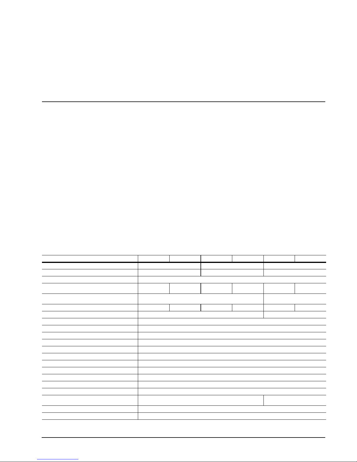
Table 1: Drive specifications summary for 400, 200 and 100 GB models
Drive specification ST400FM0012 ST400FM0052 ST200FM0012 ST200FM0052 ST100FM0012 ST100FM0062
Formatted GB (512 bytes/sector)* 400 200 100
Guaranteed logical block addresses (LBAs) 781,422,768 390,721,968 195,371,568
Emulated Bytes per LBA 512
Sustained 128KB sequentialread/write data transfer rate
(MB/s max)
Peak 128KB sequential read/write data transfer rate
(MB/s max)
Sustained 4KB Random read/write command rate (IOPs) 40,000/11,000 40,000/15,000 40,000/5500 40,000/15,000 40,000/2800 40,000/12,000
Peak 4KB Random read/write command rate (IOPs) 40,000/15,000 40,000/12,000
Flash Memory Type NAND MLC
I/O data-transfer rate (MB/s max) 600
Height (mm max) 7.00 mm (0.276 in)
Width (mm max) 70.10 mm (2.760 in)
Length (mm max) 100.45 mm (3.955 in)
Weight (max) 100 g (0.220 lb)
Average latency 206 μs
Power-on to ready (sec max) 14 sec
Standby to ready (sec max) 13 sec
Average LBA access time (μs typ) ~227 μs read; ~120 μs write
Data Retention (typical minimum at 40°C) 3 months
Sustainable 4KB Random IOPs for 5 year Endurance
(65%/35% R/W 70% Duty Cycle)
Startup current (typical) 12V / 5V (peak) 0.34 / 0.47 amps
Voltage tolerance (including noise) 12V ± 5% / 5V ± 5%
370/140 370/200 370/70 370/200 370/35 370/190
370/200 370/190
23,000 22,000
Pulsar.2 Product Manual, Rev. B 5
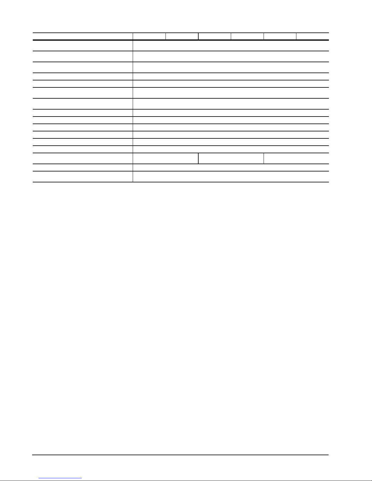
Drive specification ST400FM0012 ST400FM0052 ST200FM0012 ST200FM0052 ST100FM0012 ST100FM0062
Case temperature
Temperature gradient (°C per hour max)
Relative humidity
Relative humidity gradient 20% per hour max
Wet bulb temperature (°C max) 28
Altitude, operating
Altitude, nonoperating
(below mean sea level, max)
Operational Shock (max at 0.5ms) 1000 Gs
Non-Operational Shock (max at 0.5ms) 1000 Gs
Vibration, random operating 20–2000 Hz: 11.08 Grms
Vibration, random nonoperating 20–2000 Hz: 11.08 Grms
Nonrecoverable read errors, max 1 LBA per 10
Annualized Failure Rate (AFR) 0.44%
Warranty **
Lifetime Power cycles 50,000
Supports Hotplug operation per
Serial ATA Revision 2.6 specification
Managed Life
Usage Based
0° to 60°C (operating)
–40° to 70°C (nonoperating)
20°C (operating)
20°C (nonoperating)
5% to 95% (operating)
5% to 95% (nonoperating)
–60.96 m to 3048 m
(–200 ft. to 10,000+ ft.)
–60.96 m to 12,192 m
(–200 ft to 40,000+ ft)
16
bits read
Managed Life
Usage Based
Yes
Managed Life
Usage Based
*One GB equals one billion bytes when referring to drive capacity. Accessible capacity may vary depending on operating environment and
formatting.
**Warranty terms will vary based on type of warranty chosen: “Managed Life” or “Usage Based”. Consult your Seagate sales representative
for warranty terms and conditions.
6 Pulsar.2 Product Manual, Rev. B

2.2 Formatted capacity
Model Formatted capacity* Guaranteed LBAs Emulated LBA Size (Bytes)
ST400FM0012
ST400FM0052
ST200FM0012
ST200FM0052
ST100FM0012
ST100FM0062
*One GB equals one billion bytes when referring to drive capacity. Accessible capacity may vary depending on operating environment and
formatting.
400GB 781,422,768
200GB 390,721,968
100GB 195,371,568
512
2.2.1 LBA mode
When addressing these drives in LBA mode, all blocks (LBAs) are consecutively numbered from 0 to n–1,
where n is the number of guaranteed LBAs as defined above.
See Section 4.3.1, "Identify Device command" (words 60-61 and 100-103) for additional information about 48bit addressing support of drives with capacities over 137GB.
2.3 Default logical geometry for ATA based systems
Cylinders Read/write heads Sectors per track
16,383 16 63
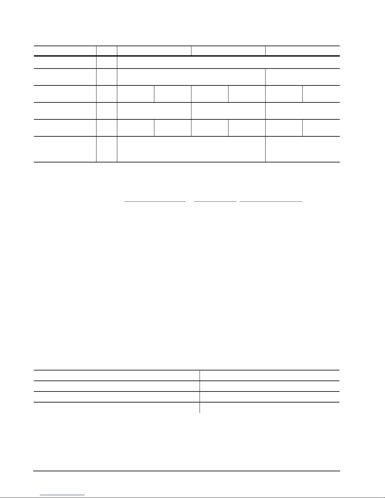
2.4 Performance, Recording and interface technology
2.4.1 Interface technology
ST400FM0012 ST400FM0052 ST200FM0012 ST200FM0052 ST100FM0012 ST100FM0062
Interface
Interface Speeds
Supported
Maximum Burst
Transfer Rate
Hot Plug Support
Native Command
Queuing Support
Trim Support
Lifetime Endurance
Management
2.4.2 Recording technology
Flash Memory Type NAND MLC
Emulated LBA Size (Bytes) 512
Native Programmable Page size (User Bytes) 8192
Default transfer alignment offset 0
Typical Data Retention with Power removed (at 40°C) 3 months
Serial ATA (SATA-II)
6Gb/s, 3Gb/s, 1.5Gb/s
600MB/s
Yes
Yes
Yes
Yes
No
Yes
No
Yes
No
Pulsar.2 Product Manual, Rev. B 7
2.4.3 Performance
Notes ST400FM0012 ST400FM0052 ST200FM0012 ST200FM0052 ST100FM0012 ST100FM0062
Maximum Burst Transfer
Rate
Peak sequential 128KB
read/write data transfer rate
(MB/s max)
Sustained sequential
128KB read/write data
transfer rate (MB/s)
Peak 4KB random
read/write command
rate (IOPs)
Sustained 4KB random
read/write command
rate (IOPs)
Sustainable 4KB Random
combined IOPS for 5 year
Endurance
(65%/35% R/W, 70% Duty
Cycle)
[1] 370/200 370/190
[1] 370/140 370/200 370/70 370/200 370/35 370/190
[2] 40,000/15,000 40,000/12,000
[2] 40,000/11,000 40,000/15,000 40,000/5500 40,000/15,000 40,000/2800 40,000/12,000
[3] 23,000 22,000
600MB/s
[1] Testing performed at Queue Depth = 32, Sequentially Preconditioned drive, using IOMeter 2006.7.27.
[2] Testing performed at Queue Depth = 32, Randomly Preconditioned drive, using IOMeter 2006.7.27.
[3] Testing performed at Queue Depth = 32, Non-Preconditioned drive, using IOMeter 2006.7.27.
Note. IOMeter is available at http://www.iometer.org/ or http://sourceforge.net/projects/iometer/.
IOMeter is licensed under the Intel Open Source License and the GNU General Public License. Intel
does not endorse any IOMeter results.
Peak performance is defined as the typical best case performance that the product will be able to
achieve when the product is preconditioned as mentioned and host commands are aligned on 4KB
boundaries.
Sustained performance is defined as the typical worst case performance that the product will be able to
achieve when the product is preconditioned as mentioned and host commands are aligned on 4KB boundaries. For models that support Lifetime Endurance Management, write values also take into account the worst
case performance throttling that may occur to ensure the product meets specified reliability specifications.
Due to the nature of Flash memory technologies there are many factors that can result in values different than
those stated in this specification. Some discrepancies can be caused by bandwidth limitations in the host
adapter, operating system, or driver limitations. It is not the intent of this manual to cover all possible causes of
performance discrepancies.
When evaluating performance of SSD devices, it is recommended to measure performance of the device in a
method that resembles the targeted application using real world data and workloads. Test time should also be
adequately large to ensure that sustainable metrics and measures are obtained.
2.5 Physical characteristics
Maximum height 7.00 mm (0.276 in)
Maximum width 70.10 mm (2.760 in)
Maximum length 100.45 mm (3.955 in)
Max weight 100 g (0.220 lb)
8 Pulsar.2 Product Manual, Rev. B
2.6 Access time
Access measurements are taken with nominal power at 25°C ambient temperature. All times are measured
using drive diagnostics. The specifications in the table below are defined as follows:
• Page-to-page access time is an average of all possible page-to-page accesses in both directions for a
sequentially preconditioned drive.
• Average access time is a true statistical random average of at least 5000 measurements of accesses
between programmable pages, less overhead, on a randomly preconditioned drive.
*Typical access times (μs) Read Write
Page-to-page 60 120
Average 227 120
Average latency: 206
Note. These drives are designed to provide the highest possible performance under typical conditions.
However, due to the nature of Flash memory technologies there are many factors that can result in
values different than those stated in this specification.
2.7 Time to Ready
400GB 200GB 100GB
Power-on to Ready for non-Media related Commands (sec) 3 (max)
Power-on to Ready for Media related commands (sec) 14 (max)
Standby to Ready (sec) 13 (max)
Ready to power removal (sec) 3 (max)
Power-on to Ready for non-media related commands is defined as the time that it will take the drive to respond
from the application power until it is ready to accept commands from the host that do not require access to the
flash media. In some cases the drive may accept media access commands during this time, but the commands
will not be completed or status returned to the host until the media can be accessed safely. Commands such
as Check Power and Identify are examples of non-media related commands.
Power-on to Ready for media related commands is defined as the time that it will take the drive to respond from
the application power until it is ready to accept commands from the host that require access to the flash media.
Commands such as FPDMA Read Extended and FPDMA Write Extended are examples of media related commands. This value includes the time needed to charge the Power Loss Data Protection Circuit to a level that is
adequate to protect customer data from unexpected power loss
Pulsar.2 Product Manual, Rev. B 9

2.8 Power specifications
The drive receives DC power (+12V / +5V) through a native SATA power connector. See Figure 7 on page 25.
2.8.1 Power consumption
Power requirements for the drives are listed in the table on page 9. Typical power measurements are based on
an average of drives tested, under nominal conditions, at 35°C ambient temperature.
• Startup power
Startup power is measured from the time of power-on to the time that the drive reaches operating condition
and can process media access commands.
• Peak operating mode
During peak operating mode, the drive is tested in various read and write access patterns to simulate the
worst-case power consumption.
• Idle mode power
Idle mode power is measured with the drive powered up and ready for media access commands, with no
media access commands having been received from the host.
• Standby mode
During Standby mode, the drive accepts commands, but not be able to immediately access the media
because the drive electronics are in a partial power-down mode.
10 Pulsar.2 Product Manual, Rev. B
 Loading...