

User and maintenance manual
for generating sets
R34
0
U
33504081101NE_0_1

CALIFORNIA
Proposition 65 Warning
Diesel engine exhaust and some of its
constituents are known to the State of
California to cause cancer, birth
defects, and other reproductive harm.
If this product contains a gasoline engine
WARNING
The engine from this product contains
chemicals known to the State of California to
cause cancer, birth defects or other
reproductive harm
The state of California requires the above two warnings.

1. Preface ............................................................................................................................................................................................ 3
1.1. General recommendations ................................................................................................................................................. 3
1.2. Pictograms and their meanings .......................................................................................................................................... 4
1.3. Instructions and safety regulations ..................................................................................................................................... 8
1.3.1 General advice ................................................................................................................................................................... 8
1.3.2 Risks related to exhaust gases and fuels ........................................................................................................................... 9
1.3.3 Risks related to toxic products ......................................................................................................................................... 10
1.3.4 Risk of fire, burns and explosion ...................................................................................................................................... 10
1.3.5 Risks related to electrical networks .................................................................................................................................. 11
1.3.6 Dangers presented by electric currents (first aid) ............................................................................................................. 11
1.3.7 Risks related to moving the set ........................................................................................................................................ 11
1.4. Identifying sets ................................................................................................................................................................. 12
2. General description ........................................................................................................................................................................ 14
2.1. Description ....................................................................................................................................................................... 14
2.2. Technical specifications ................................................................................................................................................... 17
2.3. Fuel and consumables ..................................................................................................................................................... 19
2.3.1 Specifications ................................................................................................................................................................... 19
2.3.1.1. Oil grades ............................................................................................................................................................ 19
2.3.1.2. Specifications of coolants .................................................................................................................................... 20
3. Installation ...................................................................................................................................................................................... 21
3.1. Unloading ......................................................................................................................................................................... 21
3.1.1 Safety during unloading ................................................................................................................................................... 21
3.1.2 Instructions for unloading ................................................................................................................................................. 21
3.1.2.1. Slings .................................................................................................................................................................. 21
3.1.2.2. Fork lift truck ........................................................................................................................................................ 22
3.2. Fluid retention ................................................................................................................................................................... 22
3.3. Choice of location ............................................................................................................................................................. 24
3.4. Electricity .......................................................................................................................................................................... 25
3.5. Special arrangements ...................................................................................................................................................... 26
4. Trailer ............................................................................................................................................................................................. 27
4.1. Trailer linkage ................................................................................................................................................................... 27
4.2. Check before towing ......................................................................................................................................................... 27
4.3. Operation ......................................................................................................................................................................... 28
4.4. Unhitching the trailer ........................................................................................................................................................ 28
4.5. Implementation for installation .......................................................................................................................................... 29
4.6. Break transmission adjustment ........................................................................................................................................ 29
4.7. Faults and repairs ............................................................................................................................................................. 31
4.8. Electrical connection diagram ........................................................................................................................................... 32
4.9. Complete wheels technical information ............................................................................................................................ 32
5. Preparation before operating the set ............................................................................................................................................. 33
5.1. Installation checks ............................................................................................................................................................ 33
5.2. Checks after starting the generating set ........................................................................................................................... 33
6. Using the generator set .................................................................................................................................................................. 33
6.1. Pre-Start Inspection .......................................................................................................................................................... 33
6.2. Generator set with TELYS control panel .......................................................................................................................... 35
6.2.1 Control panel presentation ............................................................................................................................................... 35
6.2.1.1. View of the front panel ......................................................................................................................................... 35
6.2.1.2. Description of the screen ..................................................................................................................................... 37
6.2.1.3. Description of the pictograms in zone 1 .............................................................................................................. 38
6.2.1.4. Description of the pictograms in zone 2 .............................................................................................................. 39
6.2.1.5. Description of the pictograms in zone 3 .............................................................................................................. 40
6.2.1.6. Display of messages in zone 4 ............................................................................................................................ 43
6.2.2 Starting ............................................................................................................................................................................. 47
6.2.3 Switching off ..................................................................................................................................................................... 48
6.2.4 Alarms and faults ............................................................................................................................................................. 48
6.2.4.1. Viewing alarms and faults ................................................................................................................................... 48
6.2.4.2. Activation of an alarm or fault .............................................................................................................................. 49
6.2.4.3. Activation of an alarm and a fault ........................................................................................................................ 50
6.2.4.4. Engine fault codes display ................................................................................................................................... 51
6.2.4.5. Horn reset ........................................................................................................................................................... 52
1/285

6.3.
Generator set with KERYS control panel .......................................................................................................................... 53
6.3.1 Presentation of the KERYS............................................................................................................................................... 53
6.3.1.1. Operating conditions ............................................................................................................................................ 53
6.3.1.2. Conformity to legal and regulatory requirements ................................................................................................. 54
6.3.2 Description of the KERYS ................................................................................................................................................. 55
6.3.2.1. Identification of the hardware components .......................................................................................................... 55
6.3.2.2. Identification of the software components ............................................................................................................ 58
6.3.3 Description of the Man Machine Interface (IHM / MMI) ..................................................................................................... 59
6.3.3.1. The Man Machine Interface ................................................................................................................................. 59
6.3.3.2. Navigation in the screens ..................................................................................................................................... 62
6.3.4 Configurations ................................................................................................................................................................... 67
6.3.4.1. Operating principle ............................................................................................................................................... 67
6.3.4.2. Legends ............................................................................................................................................................... 68
6.3.4.3. Configuration in solo generating set..................................................................................................................... 68
6.3.4.4. Power plant configuration (Several generating sets in parallel) ........................................................................... 71
6.3.5 Connections of the generating sets .................................................................................................................................. 78
6.3.5.1. Recommendations before the connections .......................................................................................................... 78
6.3.5.2. Connections according to the configurations ....................................................................................................... 78
6.3.5.3. Earthing system (Standard only) .......................................................................................................................... 79
6.3.5.4. Facility power outlet ............................................................................................................................................. 83
6.3.5.5. Connecting cable between the generating sets (power plant) ............................................................................. 84
6.3.5.6. Power ................................................................................................................................................................... 85
6.3.5.7. Client terminal block ............................................................................................................................................. 85
6.3.6 Operation and setting menus ............................................................................................................................................ 86
6.3.6.1. Layout of the menus ............................................................................................................................................ 86
6.3.6.2. Setting of regional parameters ............................................................................................................................. 87
6.3.6.3. Information on the KERYS ................................................................................................................................... 89
6.3.6.4. Operating menus ................................................................................................................................................. 91
6.3.7 Rental configurations ........................................................................................................................................................ 93
6.3.7.1. Choice of application configuration ...................................................................................................................... 93
6.3.8 Use ................................................................................................................................................................................. 102
6.3.8.1. Choice of priority generating set in power plant (if equipped) ............................................................................ 102
6.3.8.2. Starting, tests and stop ...................................................................................................................................... 108
6.3.8.3. Rental options .................................................................................................................................................... 115
7. Maintenance schedule .................................................................................................................................................................. 117
7.1. Reminder of use .............................................................................................................................................................. 117
7.2. Engine ............................................................................................................................................................................. 117
7.3. Alternator ........................................................................................................................................................................ 118
8. Battery .......................................................................................................................................................................................... 119
8.1. Storage and transport ..................................................................................................................................................... 119
8.2. Battery setting into service .............................................................................................................................................. 120
8.3. Check .............................................................................................................................................................................. 120
8.4. Load preconization .......................................................................................................................................................... 121
8.5. Faults and remedies ....................................................................................................................................................... 122
9. Appendix ...................................................................................................................................................................................... 123
9.1. Appendix A – Engine user and maintenance manual ..................................................................................................... 123
9.2. Appendix B - Alternator user and maintenance manual .................................................................................................. 209
9.3. Appendix C - Common spare parts ................................................................................................................................. 269
9.4. Appendix D - List of John Deere - Volvo and Perkins fault codes ................................................................................... 271
2/285

1. Preface
1.1. General recommendations
Thank you for choosing an electrical generating set from our company.
This manual has been designed to help you operate and maintain your electrical generating set correctly.
The information contained in this manual is taken from technical data available at the time of print. In line with our policy of
continually improving the quality of our products, this information may be amended without warning.
Read the safety instructions attentively in order to prevent any accidents, faults or damage. These instructions must always be
followed.
You are likely to encounter several warning symbols in this manual.
This symbol indicates an immediate danger to human health and life in case of exposure. Failure to follow
the corresponding advice entails serious consequences for human health and life in case of exposure.
Danger
This symbol draws attention to the potential risks to human health and life in case of exposure. Failure to
follow the corresponding advice entails serious consequences for human health and life in case of exposure.
Warning
This symbol indicates a dangerous situation if the warning is not heeded.
Failure to follow the corresponding advice risks resulting in minor injury of personnel or damage to any other
object in case of exposure.
Important
In order to obtain optimum efficiency and the longest possible life for the electrical generating sets, maintenance operations must be
carried out according to the periods indicated in the attached preventative maintenance tables. If the electrical generating set is
used under dusty or unfavourable conditions, some of these periods will be shorter.
Ensure that all repairs and adjustments are carried out by personnel who have received appropriate training. Dealers have this
qualification, and can answer all of your questions. They can also supply you with spare parts and other services.
The left and right sides can be seen from the back of the electrical generating set (the radiator is at the front).
Our electrical generating sets have been designed so that damaged or worn parts can be replaced by new or reconditioned parts
thereby reducing the out of action period to a minimum.
For any replacement of parts, contact your nearest dealer for our company who will have the necessary equipment and can offer
properly trained and informed staff to carry out maintenance, parts replacement and even total reconditioning of generating sets.
Contact your local dealer for the available repair manuals and to make the necessary arrangements for training personnel in
implementation and maintenance.
Some user and maintenance manuals for the engines fitted to generating sets cover control units and
include the start-up and shutdown procedures for the engines.
As the generating sets are fitted with control units that are specific to the generating sets, only the
information that appears in the documentation for the generating sets' control units should be taken into
consideration.
In addition, according to the manufacturing criteria of the generating sets, some engines may be fitted with
specific electrical wiring different to that described in the engine documentation.
Important
3/285

1.2. Pictograms and their meanings
Safety notices are clearly mounted on the equipment to draw the operator's or maintenance technician's attention to the potential
dangers and explain the action to be taken in the interest of safety. These notices are reproduced in this publication for ease of
identification by the operator.
Replace any notice that is missing or illegible.
Caution: danger
Publications delivered
with the generating set
must be referred to
Caution: risk of explosion
Caution: risk of
electric shock
Protective clothing
must be worn
Naked flames and
unprotected lights
prohibited.
No smoking
Caution: toxic
materials
Eyes and ears must be
protected
Entry prohibited to nonauthorised persons
Caution:
pressurised fluids
Periodic maintenance
must be carried out
Jet washing prohibited
Caution: high
temperature, risk
of burns
Battery level must be
checked
Earth
Caution: rotating
or moving parts
(risk of getting
caught in the
machinery)
Lifting point must be
used
Caution: corrosive
product
Fork pockets for
lifting
Retention tank level
high
Important: refer to the documentation accompanying the generating set.
Important: emission of toxic exhaust gases. Do not use in a confined or badly
ventilated area.
Figure 1.1 : Pictograms and their meanings
4/285

WARNING: DANGER
This symbol warns of a safety hazard. The presence of this symbol indicates a risk
of injury.
Observe the safety instructions and precautions for use.
Important:
Carefully read the instructions supplied with the generating set before using or
servicing the equipment.
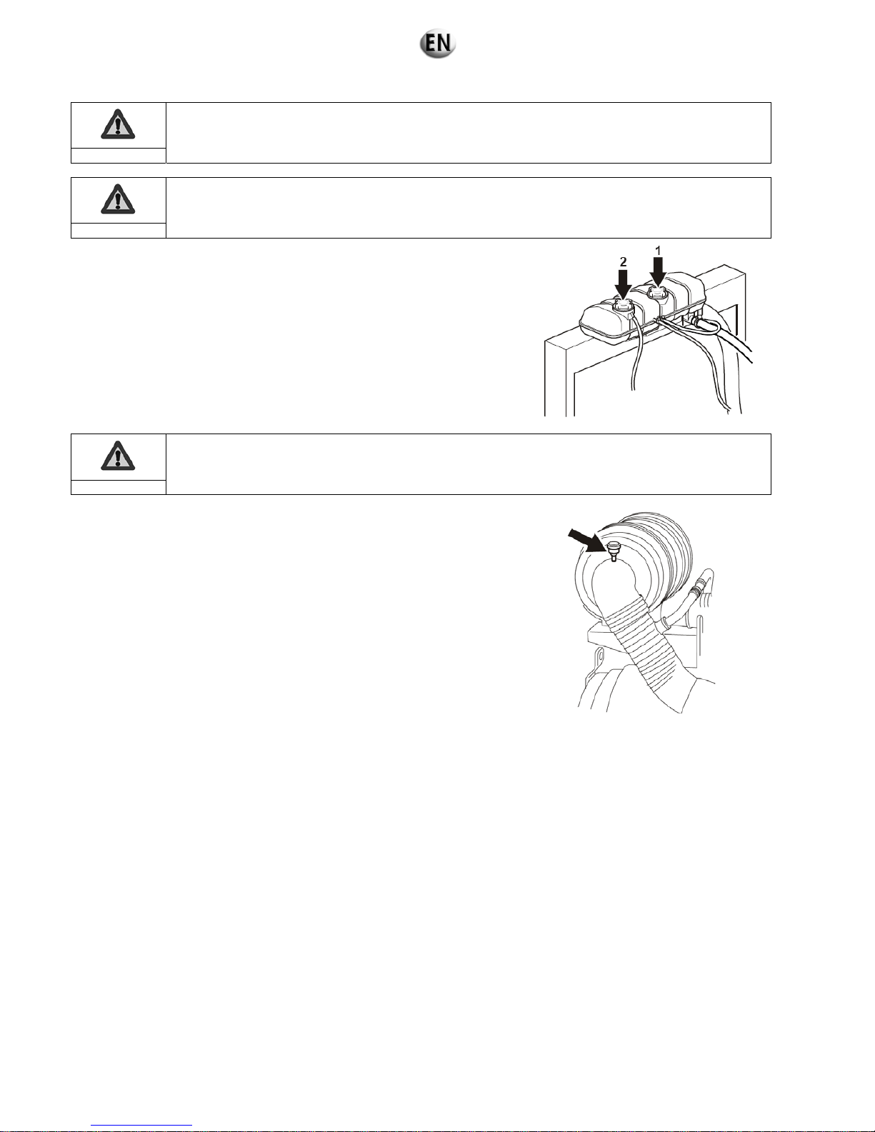
WARNING: DANGER
Risk of electrocution
Do not touch the cables or connections when the generating set is in
operation.
Switch off the generating set for maintenance operations.
DANGER
Use diesel fuel only.
The fuel is highly flammable, handle with care. Do not smoke near the
generating set or expose it to a naked flame or sparks.
Shut down the generating set engine before filling the fuel tank. Fill with fuel
outside.
To prevent fire risks, clean the generating set regularly. Wipe away any dirt
and traces of grease or fuel.
WARNING: DANGER
The exhaust gases from the engine are toxic and can affect health or even
cause death.
Use the generating set outdoors only, in well ventilated areas, or fit an exhaust
extension to discharge the exhaust gases outside.
Figure 1.2 : Pictograms and their meanings
5/285

WARNING: DANGER
Hot coolant can cause serious burns.
Switch off the engine. Do not remove the filler cap until it is completely cold.
Do not open the radiator when it is hot.
DANGER
Rotating parts can cause serious injury.
Do not operate the generating set with the doors open.
Do not remove the enclosures.
Shut down the generating set before any maintenance or servicing
operation.
DANGER
Avoid any contact with the exhaust pipes, turbochargers and silencers.
Keep flammable materials away from hot parts.
Wait for the machine to cool down completely before touching it.
WARNING: DANGER
The gas from the battery electrolyte is explosive. Keep the batteries away
from any flames.
The battery electrolyte (sulphuric acid) is toxic. Risk of poisoning.
Figure 1.2 (continued) : Pictograms and their meanings
6/285

WARNING: DANGER
A poor earth connection can lead to serious injuries or death.
Always connect the earth terminal of the generating set to an external earth
terminal.
WARNING
Voltage selector
This function should be used by qualified persons only.
WARNING
Adjust the output voltage correctly before connecting a load.
WARNING
The voltage selector must not be used when the generating set is operating.
Figure 1.2 (continued) : Pictograms and their meanings
7/285

1.3. Instructions and safety regulations
THESE SAFETY GUIDELINES ARE IMPORTANT
If you do not understand or have any questions about any point in this manual, contact your dealer who will explain it to you or give
you a demonstration. A list of risks and precautionary measures to take follows. You should also refer to any local and national
regulations that apply in accordance with your own jurisdiction.
KEEP THIS MANUAL
This manual contains important instructions which must be followed when installing or carrying out maintenance on a generating set
or batteries.
1.3.1 General advice
Use
The operating and safety instructions must be made known to operating personnel. They will be regularly updated.
Read and understand the manuals provided with the generating set, pump unit or lighting column properly. The manufacturer's
instructions must remain at the disposal of technicians, if possible in situ.
The facility must be operated under the direct or indirect supervision of a person appointed by the operator, who is familiar with
the operation of the facility, and the dangers and drawbacks of the products used or stored in the facility.
Do not wear loose clothing, or get close to machines in operation. Note that the fans are not clearly visible when the engine is
running.
Warn personnel present to keep their distance during operation.
Do not run the generating set, pump unit or lighting column without refitting the protective covers and closing all the access
doors.
Never let a child touch the generating set, pump unit or lighting column, even when shut down.
Avoid operating the generating set, pump unit or lighting tower in the presence of animals (disturbance, scares, etc.).
Engage the parking brake when the generating set or lighting tower on its trailer is installed on the operating site. When
chocking the trailer on a slope; ensure that there is nobody in the path of the trailer.
Never start the engine without an air filter or exhaust.
Engine with turbocharger: never start the engine without fitting the air filter. The compressor wheel rotating inside the
turbocharger may cause serious bodily injury. Foreign objects in the inlet pipe may cause mechanical damage.
Engine with air preheating (starting components): never use a starting spray or any other similar starter assistance product.
Upon contact with the starting component, an explosion may occur in the inlet tube, causing bodily injury.
Do not touch the lighting column lights when they are switched on.
Maintenance
Follow the maintenance table and its instructions.
Always use tools in good condition which are suited to the work to be done. Ensure you have understood the instructions before
beginning any operation.
Goggles should be worn when carrying out maintenance operations and watches, bracelets etc. should be removed.
Fit only original parts.
Disconnect the battery and the pneumatic starter (if fitted) before undertaking any repairs, to prevent the engine from starting
accidentally. Fit a panel over the controls to prevent any attempt to start.
Only use the correct crankshaft turning techniques for turning the crankshaft manually. Do not try to turn the crankshaft by
pulling it or levering the fan. This method may cause serious bodily or material damage, or damage the vanes of the fan,
reducing the service life of the fan.
Clean off any trace of oil, fuel or coolant using a clean cloth.
Do not use a soapy solution containing either chlorine or ammonia, as these two chemicals prevent bubble formation.
Never use petrol or other inflammable substances to clean the parts. Use only approved cleaning solvents.
Do not use a high pressure cleaner for cleaning the engine and equipment. The radiator, hoses, electrical components, etc. may
be damaged.
Avoid accidental contact with parts at high temperatures (exhaust manifold, exhaust).
Before any maintenance operation on a lighting column light, cut the electrical power supply and wait for the bulbs to cool down.
Consumables
Observe regulations in force concerning use of fuel before using your generating set, pump unit or lighting tower.
Under no circumstances use seawater or any other corrosive or electrolytic product in the cooling circuit.
8/285

Environment
The operator must take the necessary measures to comply with the aesthetics of the site of use. The whole site must be
maintained in a good state of cleanliness.
The premises must be kept clean, and be regularly cleaned so as to avoid accumulation of dangerous materials or pollutants
and dust, which could ignite or cause an explosion. The cleaning equipment must be suited to the risks posed by the products
and dust.
The presence of dangerous or combustible materials inside premises housing combustion devices shall be limited to the
operating requirements.
Facilities must be operated under the constant supervision of a qualified person, who must regularly check that the safety
devices are operating correctly and ensure that the combustion devices have the correct fuel supply.
Apart from the combustion devices, it is prohibited to use fire in any form. This restriction must be clearly displayed.
Spreading of waste water, sludge and waste is prohibited.
The fuels to be used must correspond to those featured in the declaration file and the specifications recommended by the
combustion device manufacturer.
The fuel is considered to remain in the same physical state as when it is introduced into the combustion chamber.
Burning of waste in the open air is prohibited.
Always protect your hands when checking for leaks. Pressurised liquids may penetrate body tissue and cause serious damage.
Risk of blood contamination.
Drain and dispose of engine oil in a specially provided container (fuel distributors can collect your used oil).
Except by special agreement, once closed, the gas supply main unit must only be re-opened by the gas distributor. However,
the user may access it under certain conditions. Check these for each site.
1.3.2 Risks related to exhaust gases and fuels
The carbon monoxide present in exhaust gases may cause death if the concentration levels in the air
breathed are too high.
Always use generating sets, pump units or lighting towers in a well-ventilated place where gases cannot
accumulate.
In case of indoor use:
Be sure to evacuate exhaust gases outdoors.
Provide appropriate ventilation so that personnel present are not affected.
Danger
Observe the local regulations in force for generating sets, pump units or lighting towers, as well as local regulations for use of
fuel (petrol, diesel fuel and gas) before using your generating set, pump unit or lighting tower.
Fuel filling should be carried out when the engine is off (except for generating sets with an automatic filling system).
Engine exhaust gases are toxic: do not run the generating set, pump unit or lighting column in unventilated premises. If installed
in a ventilated room, additional requirements for fire and explosion protection must be observed.
A leaking burnt gas exhaust may increase the sound level of the generating set, pump unit or lighting column. To check on its
efficiency, regularly examine the burnt gas exhaust.
Pipes must be replaced as soon as their condition demands it.
9/285
1.3.3 Risks related to toxic products
The corrosion inhibitor contains alkali.
Do not swallow it.
This substance should not come into contact with the
eyes. In the event of contact with the eyes, rinse
immediately with plenty of water for at least 15
minutes.
Avoid prolonged or repeated contact with the skin. In
the event of contact with the skin, wash thoroughly
with water and soap. CONSULT A DOCTOR
IMMEDIATELY. KEEP THE PRODUCT OUT OF
THE REACH OF CHILDREN.
The anti-rust product is toxic and dangerous if
absorbed. Avoid all contact with the skin and eyes.
Read the instructions on the packaging.
Glycol is a toxic product and dangerous if absorbed.
Avoid all contact with the skin and eyes. Read the
instructions on the packaging.
Warning
Caution: fuels and oils are dangerous to inhale. Ensure proper ventilation, and use a protective mask.
Never expose the equipment to liquid splashes or rainfall, and do not place it on wet ground.
The battery electrolyte is harmful to skin and especially eyes. If splashes get into eyes, rinse immediately with running water
and/or a 10% diluted boric acid solution.
Wear protective eyewear and strong base resistant gloves for handling the electrolyte.
1.3.4 Risk of fire, burns and explosion
The engine should not be operated in environments containing explosive products. As not all of the
electrical and mechanical components are shielded, there is a risk of sparks forming.
Danger
Make sure not to create sparks or flames, and not to smoke near the batteries, as the electrolyte gases are highly flammable
(especially if the battery is charging). Their acid also poses a risk to the skin, and in particular to the eyes.
Never cover the generating set, pump unit or lighting tower with any material during operation or just after shutdown (wait for the
engine to cool).
Do not touch hot parts such as the exhaust pipe, or put combustible materials on it.
Keep all flammable or explosive materials (e.g. petrol, oil, cloth, etc.) out of the way when the set is running.
Proper ventilation is required for your generating set, pump unit or lighting column to work properly. Without this ventilation, the
engine would very quickly rise to an excessively high temperature, causing accidents or damage to the equipment and to
surrounding property.
Do not remove the radiator cap if the engine is hot and the coolant is pressurised, due to risks of burns.
Depressurise the air, oil and cooling circuits before removing or disconnecting all the fittings, pipes or connected components.
Watch out for the possible presence of pressure when disconnecting a device from a pressurised system. Do not try to find
pressure leaks by hand. Oil at high pressure can cause bodily damage.
Some preservative oils are flammable. Also, some are dangerous to inhale. Ensure proper ventilation. Use a protective mask.
Hot oil causes burns. Avoid contact with hot oil. Check that the system is no longer pressurised before carrying out any
procedures. Never start or run the engine with the oil filler cap off (oil may splash out).
Never coat the generating set, pump unit or lighting column with a thin layer of oil to protect it from rust.
Never top up the oil or coolant if the generating set, pump unit or lighting column is running, or if the engine is hot.
A generating set can only operate when stationary, and cannot be installed on a vehicle or other mobile equipment, without a
prior study taking into account the various specific features of using the generating set.
10/285

1.3.5 Risks related to electrical networks
The electrical equipment supplied with the generating set complies with standard NF C15.100 (France), or with the standards of
the countries in question.
The earth connection must be installed in accordance with the standards in force in each country in question, and with the
neutral system sold.
Read the manufacturer's identification plate carefully. The values for voltage, power, current and frequency are shown. Check
that these values match the supply use.
Never accidentally touch stripped cables or loose connections.
Never handle a generating set with wet hands or feet.
Maintain electrical wires and connections in good condition. Using equipment in poor condition can lead to electrocution and
damage to equipment.
Always disconnect the power to the equipment or facility (generating set voltage, battery voltage and network voltage) before
any operation.
The electrical connections must be made in accordance with current standards and regulations in the country of use.
Do not use faulty, poorly insulated or provisionally connected wires.
Never reverse the positive and negative terminals on batteries when connecting them. This could cause severe damage to the
electrical equipment. Follow the wiring diagram supplied by the manufacturer.
The generating set should not be connected to any other power sources, such as the mains supply network. In specific cases
where there is to be a connection to existing electrical networks, this must only be installed by a qualified electrician, who should
take the operating differences of the equipment into account, according to whether the mains supply network or generating set
is being used.
Protection against electric shocks is ensured by an assembly of specific equipment. If this needs to be replaced, it should be by
components with identical nominal values and specifications.
If the protective plates (blanking covers) need to be removed to route cables, the protector (blanking cover) must be refitted
when the operations are finished.
Due to high mechanical stresses, use only strong flexible wiring with rubber sheathing, compliant with IEC 245-4, or equivalent
wiring.
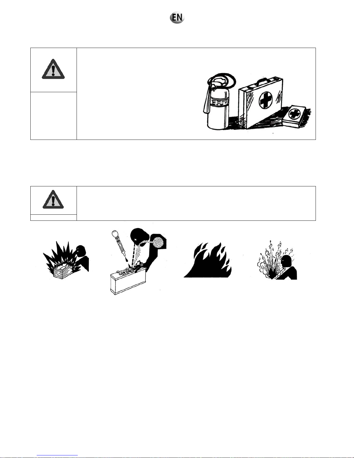
1.3.6 Dangers presented by electric currents (first aid)
First aid
In the event of an electric shock, shut off the power immediately and activate the
emergency stop on the generating set or lighting column. If the voltage has not yet
been cut off, move the victim out of contact with the live conductor as quickly as
possible. Avoid direct contact both with the live conductor and the victim's body. Use
a dry plank of wood, dry clothes or other non-conductive materials to move the victim
away. The live wire may be cut with an axe. Take great care to avoid the electric arc
that will be generated by this.
Begin emergency procedures
Resuscitation
If breathing has stopped, begin artificial respiration at once in the same place the accident took place unless the victim or operator's
life could be endangered by this.
In the event of cardiac arrest, carry out cardiac massage.
1.3.7 Risks related to moving the set
To unload the generating sets, pump units or lighting columns from their transport support brackets under optimum safety and
efficiency conditions, you must ensure that the following points are observed:
The lifting machinery or equipment is suited to the work required, in good condition and with sufficient lifting capacity.
The slings are positioned in the rings provided for this operation, the forklift arms are resting fully underneath all of the base
frame cross-beams, or the lifting bars are inserted in the apertures provided for this purpose in the base to lift the entire
generating set (according to models).
For completely safe working conditions and to prevent damage to the components fitted on the upper edge of the set, pump unit
or lighting column, the generating set, pump unit or lighting column must be lifted up with an adjustable boom. All the chains and
cables must be parallel with each other, and as perpendicular as possible with the upper edge of the generating set, pump unit
or lighting column.
If other equipment fitted on the generating set, pump unit or lighting column alters its centre of gravity, special lifting devices
may be necessary to maintain correct balance and completely safe working conditions.
The ground must be able to withstand the load of the generating set, pump unit or lighting column and its lifting machinery
without stress (otherwise, put down beams of sufficient strength in a stable configuration).
Position the generating set, pump unit or lighting column as close as possible to its place of use or transport, in a clear space
with free access.
Never perform work on a generating set, pump unit or lighting tower just hanging from a lifting device.
11/285

1.4. Identifying sets
Generating sets and their components are identified by means of identification plates.
The precise rules for identifying each major component (engine, alternator etc.) are set out in each manufacturer's documents
contained in this manual.
Examples of identification plates
Generating set
Engines
Figure 1.2 : Examples of identification plates
12/285

Alternator
Cabinet
Figure 1.3 : Examples of identification plates
13/285

2. General description
2.1. Description
Overview
1 Control unit 4 Protective grilles
2 External emergency stop 5 Chassis
3 Expansion bottle 6 Circuit breakers
Figure 2.1 : General description of the generating set
3
4
2 1
5
6
14/285
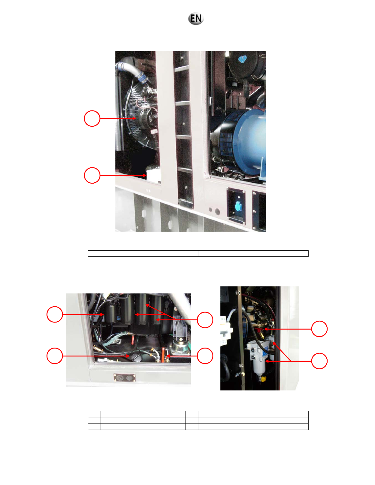
7 Battery charge alternator 8 Starter batteries
Figure 2.1 (continued): General description of the generating set
9 Coolant filter 12 External fuel supply combined tap (optional)
10 Filling with fuel 13 Circuit breaker
11 Oil filters 14 Interchangeable fuel pre-filters
Figure 2.1 (continued) : General description of the generating set
9
10
11
12
14
13
7
8
15/285

Sockets ( voltage 208/120V )
16/285

2.2. Technical specifications
Range / Generating set type RENTAL POWER / R340U
Weights and Dimensions
Dimensions with standard tank
Dimensions l x w x h:
4475 mm x 1410 mm x 2690 mm
Weight:
3830 kg dry weight 4300 kg in operating configuration
Hood:
M228C
Noise level:
80 dB à 1 m (0.70)
70 dB à 7 m (0.70)
Dimensions with high autonomy tank
Dimensions l x w x h:
4527 mm x 1410 mm x 2780 mm
Weight:
4520 kg dry weight 5888 kg in operating configuration
Hood:
M228C-DW
Noise level
:
80 dB à 1 m (0.70)
70 dB à 7 m (0.70)
Output
Voltage Hz Phase Load factor
Max current (A)
Emergency
Emergency power
1
kW / kVA
Prime power
2
kW / kVA
480/277 V 60 3 0.8 453 301.6 / 377 274.2 / 342.7
380/220 V 60 3 0.8 573 301.6 / 377 274.2 / 342.7
220/127 V 60 3 0.8 989 301.6 / 377 274.2 / 342.7
208/120 V 60 3 0.8 1046 301.6 / 377 274.2 / 342.7
(1) ESP: Stand-by output available for emergency use under variable charge up to 200hrs per year as per lSO 8528-1, no
overload available under these service conditions.
(2) PRP: Main output available continuously under variable load for an unlimited time period per year as per ISO 8528-1, an
overload of 10% one hour every 12 hours is available, as per ISO3046-1.
Engine data
Manufacturer / model VOLVO TAD941GE
Type Turbo
Cylinder configuration 6 L
Cubic capacity 9.36 L
Rotation speed 1800 Rpm
Max emergency/prime power at nominal speed 344 / 313 kW
Adjustment type Electrical
Fuel consumption
110 % (emergency power) 79.2 L/h
100 % main power 70.8 L/h
75 % main power 52.8 L/h
50 % main power 37.0 L/h
17/285
Fuel
Fuel type Diesel
Standard fuel tank 470 L
High autonomy fuel tank 1368 L
Lubrication
Oil capacity with filter 35 L
Min. Oil pressure 0.7 bar
Nominal oil pressure 6 bar
Oil consumption (100 % load) 0,06 L/h
Oil sump capacity 28 L
Type of lubricant Genlub
Cooling
Engine capacity with radiator 41 L
Max coolant temperature 103 °C
Fan power 17.8 kW
Ventilator air flow 7.2 m3/s
Refrigerant type Gencool
Thermostat 82-92°C
Alternator data
● Compliant with NEMA MG21 standards, UTE NF C51.111,
VDE 0530, BS 4999, IEC 34.1, CSA
● The alternator is protected against short circuits
● Vacuum impregnation, epoxy winding, IP23 protection rating
Type LEROY SOMER LSA462VL12
Number of phases 3
Power factor (cos Phi) 0.8
Number of poles 4
Excitation type AREP
Voltage regulator R450
Short-circuit current 3 IN
Number of bearings 1
Coupling Direct
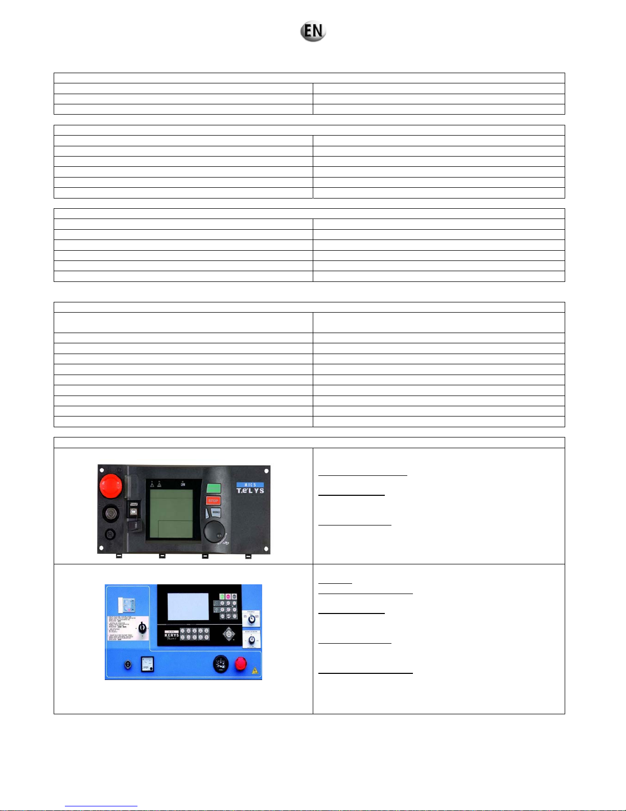
Control unit(s)
TELYS
Standard specifications:
Voltmeter, Ammeter, Frequency meter
Alarms and faults
:
Oil pressure, Water temperature, Start failure, Overspeed,
Alternator min/max, Battery voltage min/max, Emergency stop
Engine parameters
:
Timer, Oil pressure, Water temperature, Fuel level, Engine
speed, Battery voltage
KERYS
Coupling
: pre-programmed coupling mode selector.
Electrical measurements
:
Voltmeter, Ammeter, Frequency meter
Alarms and faults:
Oil pressure, Water temperature, Start failure, Overspeed,
Alternator min/max, Battery voltage min/max, Emergency stop
Engine parameters
:
Timer, Oil pressure, Water temperature, Fuel level, Engine
speed, Battery voltage
Additional specifications
:Coupling Website, Troubleshooting,
Assistance and maintenance, plotting and logging, load
impact, 8 configurations available, Compliance with
international standards…
18/285
2.3. Fuel and consumables
All specifications (product features) are given in the motor and alternator maintenance manuals attached to this manual.
In addition, we recommend the consumables to be used in the "specifications" section.
2.3.1 Specifications
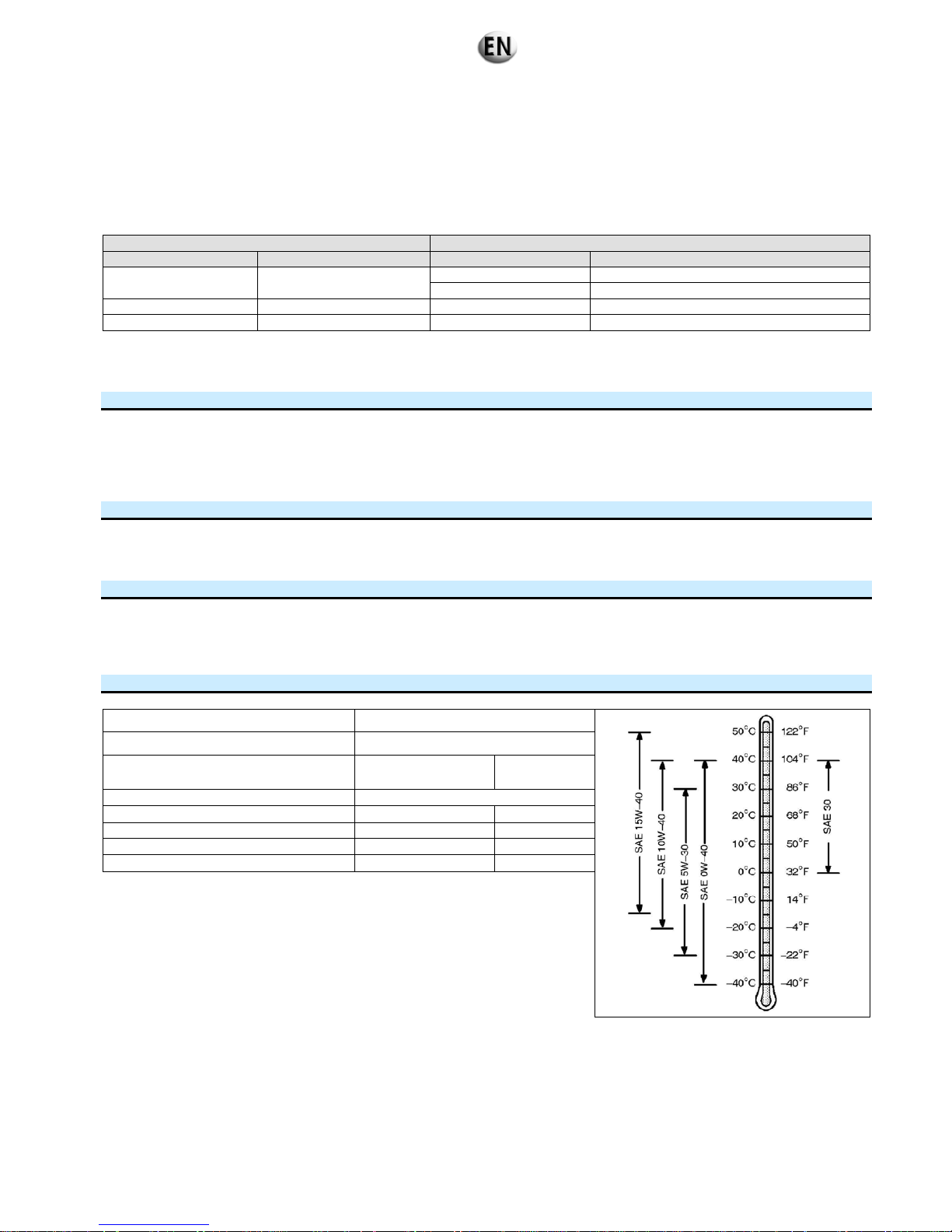
2.3.1.1. Oil grades
Engine Oil
Make Type Make Type
John Deere All
John Deere John Deere PLUS-50
GenPARTS GENLUB TDX 15W40
MITSUBISHI All GenPARTS GENLUB TDX 15W40
Volvo All GenPARTS GENLUB TDX 15W40
GENLUB TDX 15W-40
Top-of-the-range lubricant recommended for diesel engines: for generating sets used under severe conditions.
USES:
Particularly suited to more modern engines with or without turbochargers, intercoolers, or sophisticated injection systems
(e.g. HEUI, injector-pumps).
All types of use: can cope with the most demanding applications.
Depolluted engines: complies with EURO 2 and EURO 3 technology and can be used with all types of diesel fuel,
especially ecological diesel with low sulphur content.
PERFORMANCE:
ACEA E3
API CH-4
Meets level E3 of the specifications defined by European manufacturers in the ACEA standards 98 edition.
ADVANTAGES:
Less frequent oil services: this product has been put to the test during thousands of hours of use on worksites under
varying conditions, demonstrating its high quality.
Conformity with new environmental legislation: adherence to new anti-pollution standards required for new EURO 2
and EURO 3 engines.
SPECIFICATIONS:
SAE Grade 15W-40
Density at 15°C 0.883
Cinematic viscosity at 40 °C
Cinematic viscosity at 100 °C
105
14.1
mm2/s (cSt)
mm2/s (cSt)
Viscosity index 140
Dynamic viscosity at -15 °C 3000 mPa.s(cP)
Pour point - 30 °C
Flash point 220 °C
Sulphated ash content 1.4 % weight
(Values given as examples only)
19/285

2.3.1.2. Specifications of coolants
Engine Coolants
Make Type Make Type
John Deere All GenPARTS GENCOOL PC -26°C
MITSUBISHI All
Mitsubishi LLC
GenPARTS GENCOOL PC -26°C
Volvo All GenPARTS GENCOOL PC -26°C
GenCOOL PC -26
High-protection coolant, approved by manufacturers.
GenCOOL PC -26 is a ready-to-use, highly protective coolant which is produced from an antifreeze recommended by the majority
of European manufacturers.
It is made from antifreeze and G 48 inhibitors.
It protects up to -26°C.
It is free from nitrates, amines and phosphates.
It is a clear, fluorescent orange liquid.
REFERENCES/APPROVALS (for the antifreeze):
HEAVY GOODS VEHICLE LIGHTER VEHICLES
Approved by MTU, MERCEDES BENZ, MAN, KHD, GENERAL
MOTORS
Conforms with VOLVO, IVECO, VAN HOOL and STAYR
TRUCK specifications
Approved by BMW, VOLKSWAGEN, MERCEDES, PORSCHE
Conforms with VOLVO, OPEL, SEAT and SKODA specifications
Conforms with the NF R 15.601 standard
REINFORCED ANTI-CORROSION FEATURES:
Protects against high-temperature corrosion by oxidisation of ethylene (cylinder head protection).
Protects against high-temperature cavitation (top of cylinder and coolant pump protection).
Non-corrosive for seals and hoses.
Improves the efficiency and longevity of the cooling system.
GenCOOL PC -26 is especially recommended for engines fitted with aluminium or light alloy radiators.
HIGH TEMPERATURE SUITABILITY:
Provides good conditions for thermal exchange.
Perfect stability at high temperatures.
GenCOOL PC -26 is specially adapted for engines with high power densities.
LONG LASTING PROTECTION:
High alkaline reserve/stability and longevity of corrosion inhibitors.
Maintains its technical properties during prolonged use at high temperatures (neutralisation of acids).
Ensures maximum heat transfer without the build up of deposits in the cooling system.
GenCOOL PC -26 ensures optimum protection against overheating and corrosion in extreme conditions of vehicle use.
PACKAGING/STORAGE:
GenCOOL PC -26 is supplied in 210 l metallic barrels with smooth interior linings.
It can be stored for 2 years in its original container and packaging.
Avoid zinc coated containers.
20/285

RECOMMENDATIONS FOR USE:
Compatible with the original fluid.
It is recommended that the cooling system is completely drained when replacing the fluid.
SPECIFICATIONS UNITS SPECIFIED VALUES
TRIAL
METHODS
Density at 20°C
kg/m3
1,059 +/- 3
R 15-602-1
pH
pH
7.5 to 8.5
NF T 78-103
Alkalinity reserve
ml
>=10
NF T 78-101
Boiling point
°C
105 +/- 2
R 15-602-4
Freezing point:
°C
-26 +/- 2
NF T 78-102
Glassware corrosion :
(test with antifreeze)
mg/test piece
R 15-602-7
- Copper
+/- 2.6
- Weld
+/- 0.5
- Brass
+/- 2.3
- Steel
+/- 1.6
- Cast iron
+/- 0.8
- Cast aluminium
+/- 1.0
Corrosion on warm plate
(test with antifreeze)
mg/(cm²week)
+/- 0.17
R 15-602-8
3. Installation
3.1. Unloading
3.1.1 Safety during unloading
To unload electrical generating sets from their transport supports under optimum safety and efficiency conditions, you need to
ensure that the following points are observed:
- Lifting machinery or equipment appropriate to the work required.
- Slings positioned in the eyes provided for this operation or lifting arms resting fully underneath the chassis cross members.
- Ground able to take the load of the set and the lifting machinery without stress (otherwise lay down beams of sufficient strength
and stability).
- Set put down as close as possible to its point of use or transportation, in a clear area with free access.
Example of equipment to be used:
crane, slings, cross bar, safety catch, shackles.
Fork lift truck.
3.1.2 Instructions for unloading
3.1.2.1. Slings
Attach the lifting vehicle slings to the rings on the generating set designed for this procedure. Hang the slings carefully.
Check that the slings are correctly attached and the equipment is solid.
Lift the generating set carefully.
Direct and stabilise the set towards the chosen position.
Carefully set down the equipment while continuing to position it.
Release the slings, then detach and remove the lifting rings.
21/285

3.1.2.2. Fork lift truck
Position the forklift arms under the base frame (except with generating sets fitted with "forklift pockets", in which case position
the forklift arms in these pockets), making sure that only its cross-members are resting on the arms.
Lift the equipment, handling it gently.
Set down the generating set in its unloading position.
Figure 3.1: Transporting a generating set using a forklift truck
3.2. Fluid retention
Any outflow of the fluids contained in the generating sets (fuel, oil and coolant, or rainwater or condensation) will be collected in a
retention container if the generating set is fitted with this option.
The containers have a capacity which allows 110% of the fluids contained in the generating set fitted with this option to be collected.
Three different fittings are available.
Figure 3.2: Fluid retention container integrated into the tank chassis.
22/285

Figure 3.3: Offset fluid retention container underneath the generating set chassis.
Figure 3.4: Offset fluid retention container integrated into the chassis and tank.
Generating sets fitted with the offset tank option (DW) above also have a high level indicator in the retention container.
In all cases, the retention containers must be regularly checked to ensure they contain no fluid (fuel, oil and coolant, or rainwater or
condensation). If necessary, drain the containers either via the drain port or by using the drain pump (for containers fitted with this
pump).
Note: Never allow these fluids to drain onto the ground; ensure they are collected in a designated container.
23/285

3.3. Choice of location
It should be determined on the basis of use. There are no specific rules governing the choice of location, other than proximity to the
electric distribution panel and disturbances caused by the noise. However, fuel supply, burnt gas evacuation, and the direction of
these gases and the noises emitted should be taken into account.
The choice of its position will be based on carefully considered compromise!
Examples of problems that may be encountered:
Incorrect exhaust and ventilation Ground too uneven or soft.
Set incorrectly positioned
Reduced access
Fuel filling impossible Opening cover doors impossible
Figure 3.5: Examples of problems that may be encountered
24/285

3.4. Electricity
a) Connections - general information
As with low voltage electrical installations, use and maintenance is governed by standard NFC 15.100 (France) or by the standards
in the relevant country, based on international standard IEC 60364-6-61.
They must also adhere to the regulations in the NFC 15.401 application guide (France) or to the regulations and standards in the
relevant country.
b) Power cables
These can be unipolar or multipolar according to the power of the generating set.
Power cables should preferably be installed in ducts or on a cable tray for this purpose.
The cable cross-section and number of cables should be determined according to the cable type and the current standards to be
observed in the country of installation. The choice of conductors must comply with international standard
IEC 30364-5-52.
Three phase - Calculation hypothesis
Fitting method = wiring in cable runs or non perforated trays.
Permissible voltage drop = 5%
Multiconductors or single conductor joined when precision 4X…(1)
Cable type PVC 70°C (e.g. H07RNF).
Ambient temperature = 30°C.
Circuit breaker
calibre
(A)
Cable sizes
0 - 50m 51 - 100m 101 - 150m
mm²/AWG mm²/AWG mm²/AWG
10 1.5 / 14 2.5 / 12 4 / 10
16 2.5 / 12 4 / 10 6 / 9
20 2.5 / 12 4 / 10 6 / 9
25 4 / 10 6 / 9 10 / 7
32 6 / 9 6 / 9 10 / 7
40 10 / 7 10 / 7 16 / 5
50 10 / 7 10 / 7 16 / 5
63 16 / 5 16 / 5 25 / 3
80 25 / 3 25 / 3 35 / 2
100 35 / 2 35 / 2 4X(1X50) / 0
125 (1) 4X(1X50) / 0 4X(1X50) / 0 4X(1X70) / 2/0
160 (1) 4X(1X70) / 2/0 4X(1X70) / 2/0 4X(1X95) / 4/0
250 (1) 4X(1X95) / 4/0 4X(1X150) / 2350MCM 4X(1X150) / 2350MCM
400 (1) 4X(1X185) / 0400MCM 4X(1X185) / 0400MCM 4X(1X185) / 0400MCM
630 (1) 4X(2X1X150) / 2x 2350MCM 4X(2X1X150) / 2x 2350MCM 4X(2X1X150) / 2x 2350MCM
Single phase - Calculation hypothesis
Fitting method = wiring in cable runs or non perforated trays.
Permissible voltage drop = 5%
Multiconductors.
Cable type PVC 70°C (e.g. H07RNF).
Ambient temperature = 30°C.
Circuit breaker
rating (A)
Cable sizes
0 - 50m 51 - 100m 101 - 150m
mm²/AWG mm²/AWG mm²/AWG
10 4 / 10 10 / 7 10 / 7
16 6 / 9 10 / 7 16 / 5
20 10 / 7 16 / 5 25 / 3
25 10 / 7 16 / 5 25 / 3
32 10 / 7 25 / 3 35 / 2
40 16 / 5 35 / 2 50 / 0
50 16 / 5 35 / 2 50 / 0
63 25 / 3 50 / 0 70 / 2/0
80 35 / 2 50 / 0 95 / 4/0
100 35 / 2 70 / 2/0 95 / 4/0
125 50 / 0 95 / 4/0 120 / 2250MCM
c) Battery cables
Install the battery or batteries in the immediate vicinity of the electric starter motor. The cables will be connected directly from the
battery terminals to the starter motor terminals.
The primary instruction to follow is to ensure that the polarities between the battery and starter motor match. Never reverse the
positive and negative battery terminals when connecting them. This could cause severe damage to the electrical equipment.
The minimum cross-section of the cables will be 70 mm2. It varies according to the power of the starter motor but also the distance
between the batteries and the set (voltage drops on the line).
25/285
d) Safety guidelines
References: NFC 15-100:2002 (France) - IEC: 60364-5-54
In order to protect personnel against electric shocks, this generating set is equipped with a differential residual current protector
"factory" set to trigger instantly, with a sensitivity of 30 mA.
Any modification to this setting could endanger personnel. Any modification would render the user liable, and
must only be performed by qualified and authorised personnel.
When the generating set is disconnected from a facility after use, the master differential protector must be
returned to its "factory" settings, and this must be checked by trained personnel.
Important
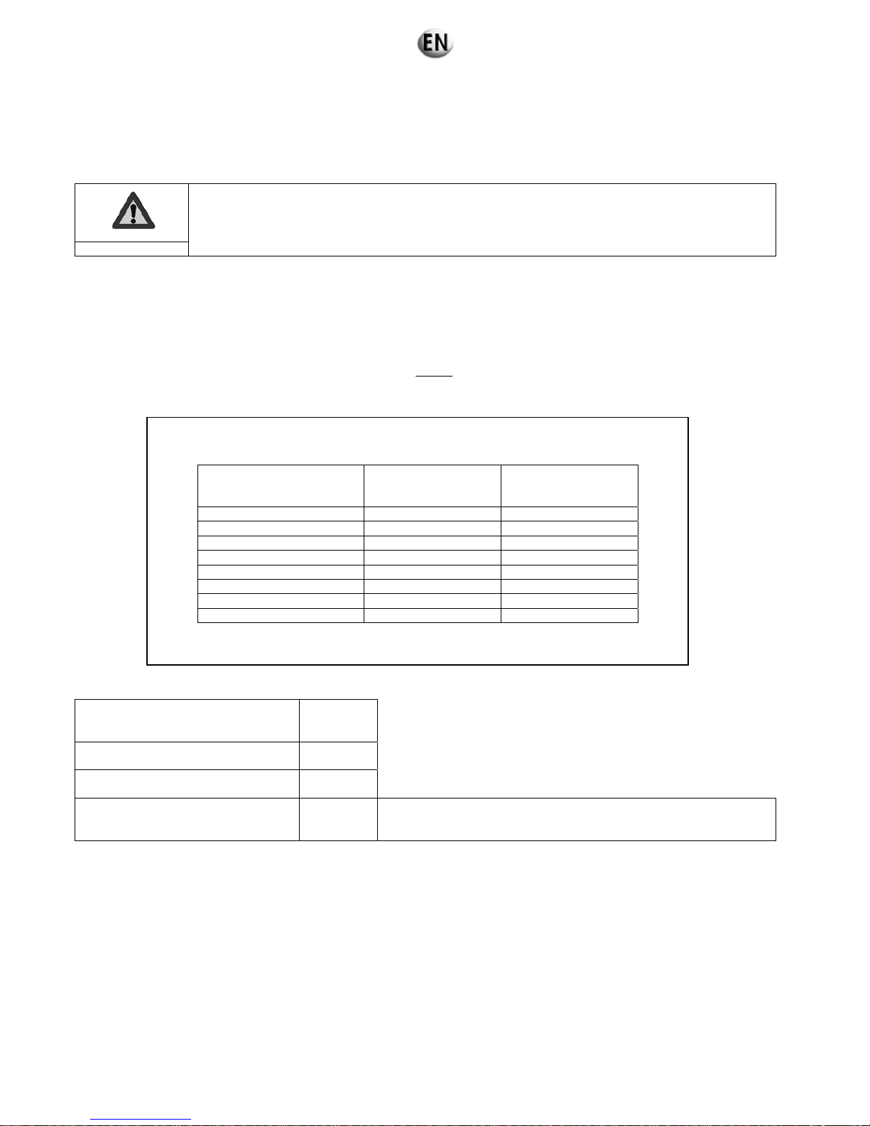
For effective protection against electric shocks, the generating set needs to be earthed. To do this, use a copper wire, with a
minimum cross-section of 25 mm2 for a stripped cable and 16 mm2 for an insulated cable, connected to the generating set earth
socket and a galvanised steel earthing rod embedded vertically into the ground.
The earthing rod resistance value should comply with the values shown in the table below.
Note: use the highest differential setting from the installation as a guideline.
The resistance value is calculated in the following way:
For a default voltage of 25 V and a default current of 30 mA, this rod must be of a minimum length of: see table below:
Nature of ground
Length of
rod in
metres
Thick arable land,
moist compact ballast
1
Lean arable land,
Gravel, coarse ballast
1
Bare stony soils, dry sand,
impermeable rock
3.6
To obtain an equivalent length, you can use several earthing rods
connected in parallel and set apart by at least their length.
Example: 4 interconnected 1 metre rods separated by 1 metre.
Note: For the United States (National Electrical Code reference NFPA-70).
The generating set must be earthed. To do this, use a copper wire with a minimum cross-section of 13.3 mm² (or AWG 6, at most)
connected to the generating set earth socket and a galvanised steel earthing rod fully embedded into the ground vertically.
This earthing rod embedded fully in the ground must have a minimum length of 2.5 m.
3.5. Special arrangements
Generating sets are not fitted with protection against power surges caused by drops in atmospheric pressure or manoeuvring.
The company does not accept any responsibility regarding damage caused by these occurrences.
However, lightning conductors can be installed, on the understanding that this does not give total protection.
R = Ul
I Δn
Maximum resistance value of the earth socket R (Ω) according to the differential unit operational
current (operation time should not be longer than 1 second).
I Δn
differential
Earth R
(Ω)
Ul: 50 V
Earth R
(Ω)
Ul: 25 V
≤ 30 mA 500 > 500
100 mA 500 250
300 mA 167 83
500 mA 100 50
1A 50 25
3A 17 8
5A 10 5
10A 5 2.5
The Ul value: 25 V is required for work site installations, and livestock buildings, etc.
26/285

4. Trailer
4.1. Trailer linkage
Before attaching the trailer, check the trailer hook on the tow vehicle; it should fit the trailer ring perfectly.
Trying to tow a trailer with a non-matching device (bar, wires, cords, etc.) could lead to serious
accidents.
Also check:
- no incipient fractures or excessive wear on the hitching system.
- locking system is operating properly.
Warning
To hitch the trailer, proceed as follows:
Lock the wheels to stop the trailer from moving
Lift up the rear trailer supports and lock them
Release the parking brake
Release the locking levers for the draw bar arms and adjust the ring to the same height as the vehicle hook
Hitch the trailer, remove the locks on each side of the wheels then lift up the front wheel fully using its handle
Connect the electrical circuit of the trailer to that of the tow vehicle
Hook the handbrake safety wire onto the hook on the tow vehicle.
Figure 4.1 : Coupling a trailer
4.2. Check before towing
Before towing, check the following:
Tightness of the generating set enclosure bolts.
Wheel tightness.
Hitching hook locked.
Tyre pressure.
Signalling lights working, for "on-road" trailers.
Enclosure doors closed.
Parking brake released, for "on-road" trailers.
Guide wheels (jockey wheels) and stands lifted (if fitted).
Towbar arm locking levers tightened and pinned (if fitted with an adjustable towbar).
Brake test, for "on-road" trailers.
Safety cable fitted, for "on-road" trailers.
Tow vehicl e
Trailer
CORRECT
To w ve h icle
Trai ler
CORRECT
To w ve h icle
Trailer
INCORRECT
To w ve h icle
Trai ler
INCORRECT
27/285

4.3. Operation
"On-site" trailer
These trailers are not fitted with a main brake, and so cannot be braked in motion; the tyres allow for a maximum speed of 27 km/h.
So it is absolutely prohibited to exceed this speed.
Nor are these trailers fitted with signalling lights. On-road use is prohibited.
"On-road" trailer
The driving speed must be suited to the condition of the road and the handling of the trailer.
Driving at high speed causes heating of the tyres; so it is important to stop from time to time, and check them. Excessive heating
may cause a puncture, and therefore a serious accident. For reversing manoeuvres, remember to lock the inertia brake.
Particular attention must be paid to the tightness of the wheels on new vehicles.
In the first few miles' driving, heating of the brake hubs and drums will actually reduce the wheel tightness. It
is therefore essential to check the tightness every 6 miles (10 kilometres) until no further loosening is noted.
Nonetheless the tightness must be checked whenever you are about to tow the trailer.
Warning
Lights/signalling (only for "on-road" trailers)
Warning lights are obligatory for on-road driving. Signalling must comply with regulations in force in the country of use.
Figure 4.2: Example of French signalling
4.4. Unhitching the trailer
This operation should be carried out on horizontal, flat, stable ground.
Lock the wheels
Lower the front wheel
Disconnect the road signals wire
Refit the hitch using the wheel to release the hook ring from the tow vehicle,
Release the tow vehicle
Engage the handbrake.
Red rear lights
+ direction indicators
+ stop lights
Front reflective devices (white)
Side reflective devices (orange)
Rear reflective devices
(
red triangle)
28/285

4.5. Implementation for installation
Operations to be carried out:
Ensure that the ground is strong enough for the assembly not to sink into it.
Unhitch the trailer.
Immobilise the trailer by placing chocks under the wheels.
Fully engage the parking brake (if fitted).
Using the front wheel, position the generating set as close to horizontal as possible.
Lower the stands (if fitted), and lock them.
4.6. Break transmission adjustment
- The handbrake is used only as a parking brake.
- Setting is carried out starting with the brakes moving to the brake control.
Important
After fitting the wheels on the axle, turn the wheels in the FORWARD direction (on all RA 2 type brakes, check that the
adjustment screw 8 reaches the “FORWARD” stop on the brake backing plate).
Adjust the brake setting using screw 8, with the cables not connected to the cross bar(s). The shoes should rub the drum
slightly.
Connect the brake cables to the cross bars(s) and tighten the nuts and lock nuts, leaving the end of the threaded end
protruding by around 10 mm (Fig. 4.4).
IMPORTANT: Wherever possible, cables must cross over to achieve the highest possible gain curve (Fig. 4.5).
Check that the parking lever 1 is in the ‘REST” position and that the compensating spring 4 is completely free on its rod
(unscrew the nuts 5 fully).
Check that the hook slide 2 is not compressed and the yoke 3 is in the pulled out position.
Fit the transmission and adjust the assembly using the tensioner 6 until a gap (J1) of 1 mm max is obtained between the
linkage 9 and slide 2.
Adjust the compensating spring 4 at one end pressing it against the anchorage plate, and at the other end leaving a 2 mm gap
(J2) max between the spring and nuts 5.
Tighten all the lock nuts.
Checking the setting (trailer on axle stands):
Pull the parking lever 2 notches - the wheels cannot turn in a FORWARD direction.
The wheels can turn in REVERSE (adjustment screw 8 switches to the REAR position).
Pull the parking lever fully.
The wheels will not turn either in FORWARD or REVERSE and the cross bar(s) must remain parallel with the axle body.
Check the transmission setting after 180 miles (300 km) (running in period) and if necessary adjust the gap (J1) using the
tensioner.
Parking
The lever must be fully pulled up, so that the compensating spring is fully compressed.
Every 900 miles (1500 km), check the braking settings and distribution on all the wheels.
Important
The brake controls are designed to draw trailers behind flexible suspension touring vehicles. If used behind an HGV, be
sure to provide the fitted ball joint with a shock absorber to prevent premature wear.
During any manoeuvres with the trailer coupled, do not turn more than 90° or force reverse.
The specifications of our brake controls are indicated on a manufacturer's plate, and the items on this should be supplied
to us when requesting replacement parts, in particular for the shock absorber, of a special type, approved by the Service
des Mines to correspond to European standards (it is advisable to have a spare shock absorber to enable instant repairs).
29/285

Figure 4.3: Braking transmission
Figure 4.4: Cross bar fitting Figure 4.5: Tandem bearing fitting
30/285

4.7. Faults and repairs
Fault observed Origin Solutions
Erratic braking of trailer - Faulty shock absorber Replace the shock absorber
Braking too weak
- Jaws worn Replace the jaws
- Jaws not run in Fault will disappear only after running in
- Incorrect linkage setting Adjust the setting
- Significant friction on the slide Grease the sliding parts
- Slide corrosion Remove the corrosion and grease
- Coupling height does not match that of
the towing vehicle
Adjust the height so that the two parts
are in the same horizontal plane
Drum temperature abnormally high
- Incorrect linkage setting Adjust the settings
- Incorrect brake setting Adjust the settings
- High levels of dust in the drums Remove the dust
- Jaws, springs, drums damaged Replace the damaged parts
- Brake cables or link rod damaged Replace the damaged parts
Jerky braking
- Incorrect linkage setting Adjust the settings
- Interfering parts on the slide Remove, clean and grease
- Corroded slide Remove the corrosion and grease
- Damage to slide guide rings
Replace the rings (and possibly the
slide) and grease
- Faulty shock absorber Replace the shock absorber
Trailer tending to swerve upon braking
- Cross-bar(s) not balanced Adjust the cross-bar(s)
- Different brake setting on the two sides Adjust the brake settings
- Cables damaged or incorrectly fitted
Replace the damaged parts
Refit the cables
- Poor load distribution Check the load distribution
When starting the trailer holds back the
towing vehicle
- Damage to slide or to guide rings Replace the faulty parts and grease
- Slide corrosion Remove the corrosion and grease
- Tie rod damaged
Replace the tie rod and adjust the
settings
- Linkage damaged or incorrectly set
Replace the damaged parts and adjust
the settings
- Brake on Loosen the brake
Play in the coupling head
- Head worn (see wear indicator) Replace the head
- Ball joint worn Replace the ball joint
Parking braking too weak
- Compensating spring incorrectly set Adjust the setting
- Braking system incorrectly set Adjust the setting
- Notched sector damaged Replace the sector and adjust the setting
- Lever ratchet worn Replace the lever and adjust the setting
- Cable ruptured Replace the cable and adjust the setting
31/285
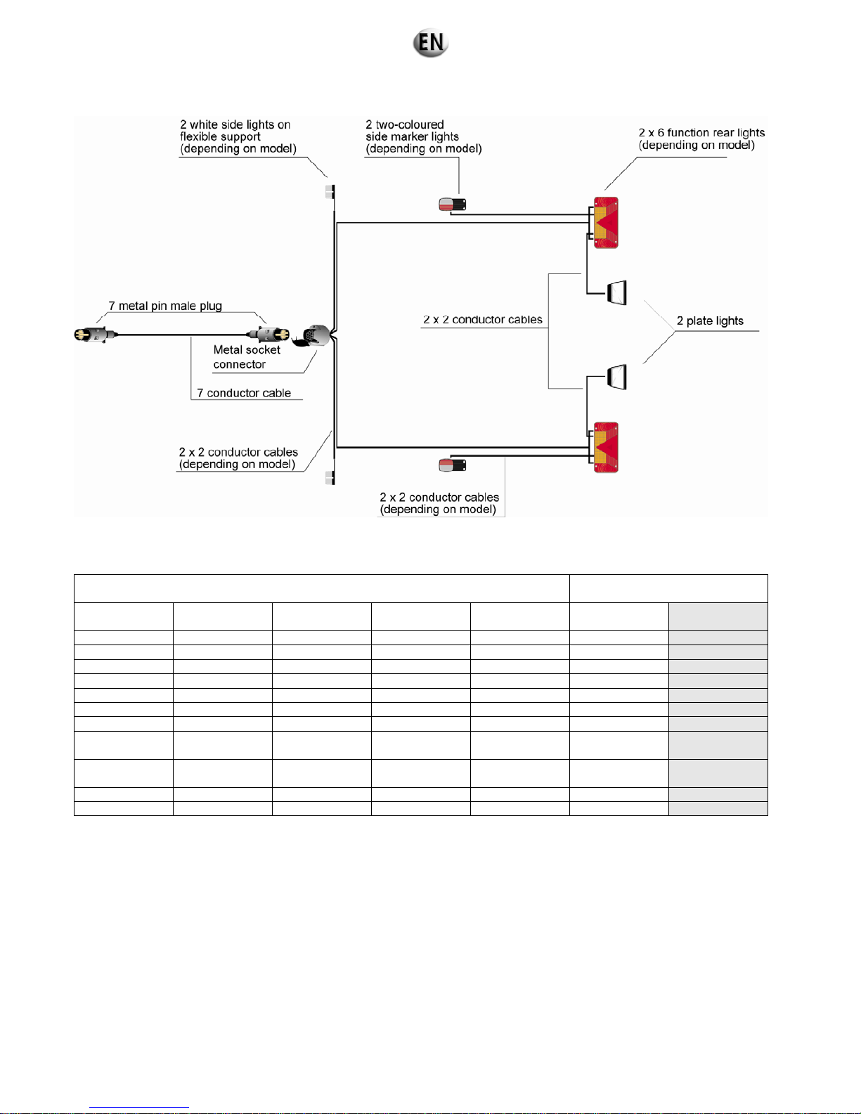
4.8. Electrical connection diagram
Figure 4.6 : Electrical connection diagram
4.9. Complete wheels technical information
TYRES
COMPLETE
WHEELS
Dimensions Indices Diameter (mm)
Cross section
(mm)
Radius under
load (mm)
Load
(Kg)
Pressure
(bar)
135 R 13 70 T 550 134 265 335 2.4
145 R 13 75 T 566 145 272 387 2.4
155 R 13 79 T 578 150 277 437 2.4
145/70 R 13 71 T 534 150 259 345 2.5
155/70 R 13 75 T 548 147 263 387 2.5
185/70 R 13 86 T 594 185 285 530 2.5
165 R 14 C 98 N 622 172 284 650 3.8
155/70 R12 100 N 525 155 244
650
(1)
800
(2)
6.25
185 R 14 C 102 P 650 188 316
675
(1)
850
(2)
4.5
195 R 14 C 106 P 666 198 32 950 4.5
195/50 x 10 98 N 450 190 - 750 6.0
(1)
Wheel with 4 holes
(2)
Wheel with 5 holes
32/285
5. Preparation before operating the set
The inspections referred to in this section enable the electrical generator set to operate.
Specific skills are required to carry out these operations.
They must only be entrusted to personnel with the necessary skills.
Failure to follow these instructions in any way could result in malfunction or very serious accidents.
Danger
5.1. Installation checks
Check that the general recommendations given in the installation section (ventilation, exhaust, fluids, etc.) are observed.
Carry out the level checks (oil, water, diesel fuel, battery).
Check the generating set earth connection is earthed.
Check that the electrical connections are in order.
5.2. Checks after starting the generating set
Carry out the mechanical checks (oil pressure, water temperature, absence of noise etc.)
Carry out the electrical checks (voltage and frequency)
Carry out the safety checks (emergency stop, oil pressure, water temperature etc.)
6. Using the generator set
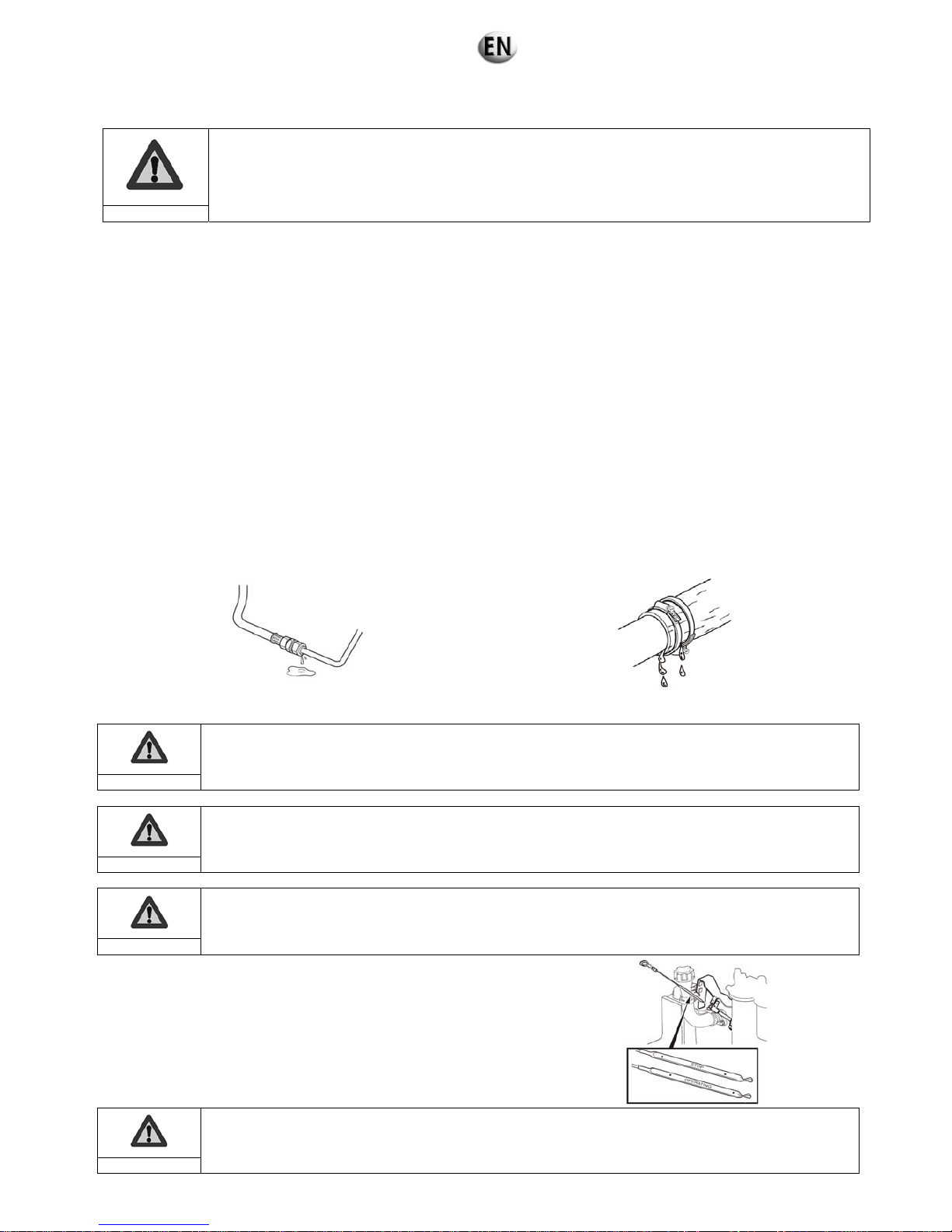
6.1. Pre-Start Inspection
• Engine and engine compartment, general check
Visually check the engine and engine compartment before starting the engine and after stopping the engine.
Check:
there are no oil, fuel or coolant leaks,
the screws are tightened,
the condition of the belts (wear, tension).
Fuel, oil and grease deposits on the engine or in the engine compartment are always a fire hazard and must be
removed as soon as they are noticed.
Warning
If there are any oil, fuel or coolant leaks, locate the origin of the fault and repair it immediately before starting
the engine.
Important
Never use a high pressure cleaner for cleaning the engine and equipment.
Important
• Oil level, check and top up
Check the oil level every day before the first start-up.
Check that it is between the MAX and MIN marks on the oil dipstick.
If necessary, top up the oil through the filler opening, on the left-hand side of
the engine.
Before checking the level again, wait a few minutes for the oil to drain into the
sump.
Never fill oil past the maximum level.
Only use oil of the recommended grade.
Important
33/285
• Coolant level, check
Do not open the filler cap when the engine is hot, except in an emergency. Boiling liquid or vapour may be
ejected.
Warning
The system must be filled up with liquid which has identical proportions to that already contained in the cooling
system.
Only open the filler cap (1).
Important
The coolant level must be between the MIN and MAX marks. Top up the oil if
necessary.
• Checking the air filter clogging indicator
Special air filters must be used for extremely dusty conditions.
Important
Replace the filter when the indicator remains in the red zone after the engine
has been stopped.
Reset the indicator after the filter has been replaced by pressing the button.
34/285

6.2. Generator set with TELYS control panel
6.2.1 Control panel presentation
6.2.1.1. View of the front panel
Figure 6.4 : View of the front panel
1 Emergency stop button (AU) for switching off the generating set in the event of a fault which could endanger personnel or
damage equipment.
2 Key switch for switching the module on/off.
3 Electronic board protection fuse.
4 Scrolling and selection wheel for scrolling through the menus and screens and selecting items simply by pressing the wheel.
5 STOP button, press to switch off the generating set.
6 START button, press to switch on the generating set.
7 Power ON LEDs and alarm/fault warning LEDs.
8 Location of USB ports.
9 Mounting bolt.
10 LCD for displaying alarms and faults, operating statuses, electrical and mechanical quantities.
11 ESC button: for returning to the previous selection and for default RESET function.
12 MENU button for accessing the menus.
13 Lighting for the emergency stop button.
2
1
3
5
9
6
7
8
4
9
10
9
11
12
13
9
35/285

Figure 6.5 : Description of the LEDs
A lit LED indicates:
1 Alarm activated (flashing yellow).
2 Fault found (flashing red).
3 Module on (green, on continuously).
Figure 6.6: Close-up of USB ports
1 USB key connection (HOST): file transfer between USB key and TELYS and vice versa.
2 Connection for microcomputer (DEVICE):
file transfer between PC and TELYS and vice versa,
main module power supply.
3 Protective cover.
2
3
1
1 2 3
36/285
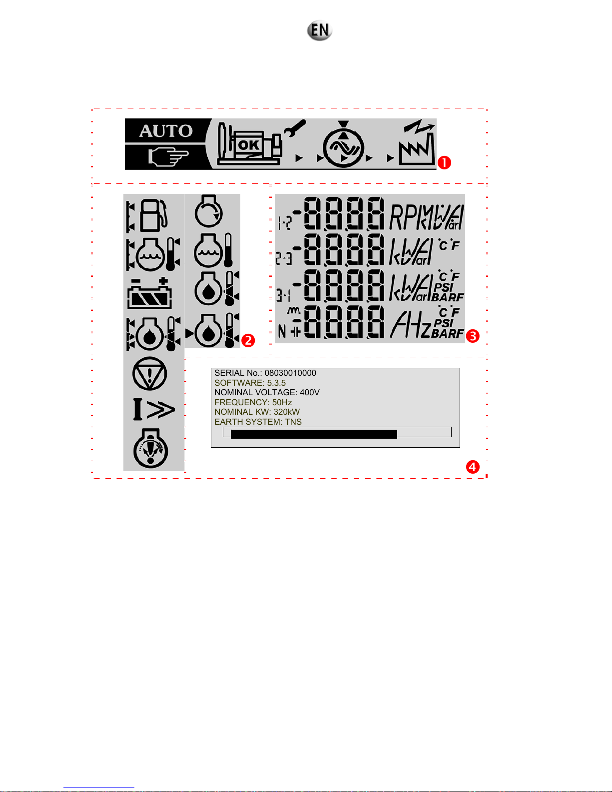
6.2.1.2. Description of the screen
The screen is backlit and requires no contrast adjustments. This screen is divided into 4 zones.
SERIAL No.: 08030010000
SOFTWARE: 5.3.5
NOMINAL VOLTAGE: 400V
FREQUENCY: 50Hz
NOMINAL KW: 320kW
EARTH SYSTEM: TNS
Figure 6.7: Description of the screen (example)
Zone 1: in this zone, the status of the generating set is displayed
Zone 2: in this zone, pictograms relating to dimensions measured are displayed, as well as Alarm and Fault pictograms
Zone 3: in this zone, the measured values corresponding to the measured dimensions are displayed with the corresponding
units of measurement
Zone 4: in this zone, messages relating to the control of the generating set and the menus are displayed.
Note: the information displayed on measurements, alarms and faults as well as messages and menus relating to control of the
generating set will depend on the equipment level of each generating set. Certain screens may therefore not be present.
37/285
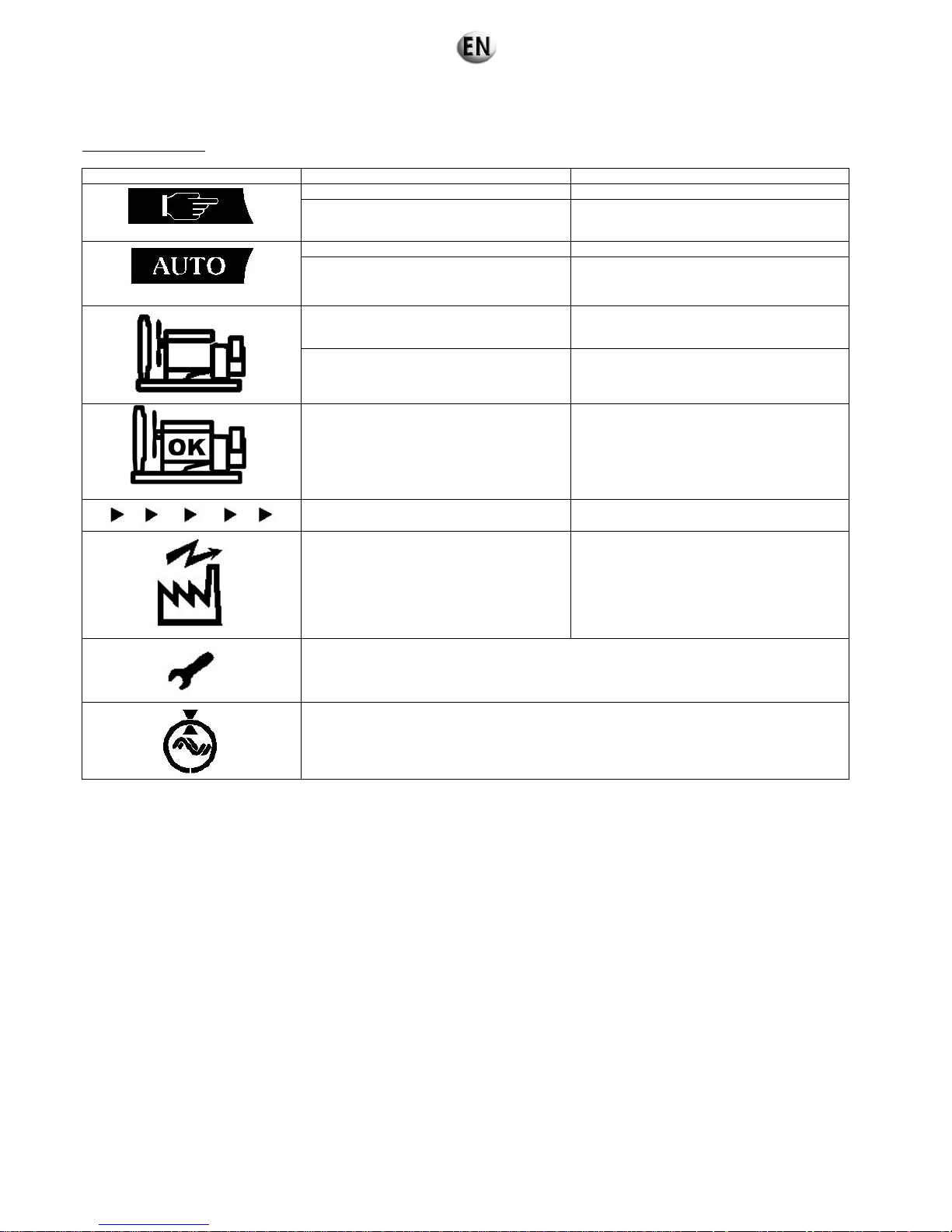
6.2.1.3. Description of the pictograms in zone 1
Pictograms in zone 1
Pictograms Display
A
ctivation conditions
"MANU" Mode
Fixed TELYS in manual mode (MANU)
Flashing
For 5 seconds when switching from AUTO
mode to MANU mode
"AUTO" Mode
Fixed TELYS in automatic mode (AUTO)
Flashing
For 5 seconds when switching from MANU
mode to AUTO mode
Flashing Generating set in start-up phase
Fixed Generating set started
Fixed
Generating set stabilised (voltage and
frequency)
Flashing (appearance of constant
movement from left to right)
The generating set is powering the
installation
Fixed The installation is supplied
Not used
Not used
38/285

6.2.1.4. Description of the pictograms in zone 2
Alarm and fault pictograms in zone 2
All the pictograms in this zone are activated when TELYS is initialised.
Data displayed
Fuel level indicator
Alarm / Fault
low fuel level
Alarm / Fault
high fuel level
Coolant level / temperature indicator
Alarm
Low level
fault
High
level fault
alarm
Alarm
High
temperature
fault
No preheating
fault
alarm
Battery
Min battery
voltage
(flashing)
Max battery
voltage (flashing)
Battery charge
indicator
(flashing bars)
Oil pressure / temperature indicator
Oil pressure
Alarm / Fault
High or low oil
level
Alarm /
Fault
High or low oil
temperature
Alarm / Fault
Emergency stop
Emergency stop fault
Overload or short circuit
Tripping of circuit breaker following an overload
or short circuit
Engine speed
Underspeed fault
Overspeed fault
Non-starting fault
39/285
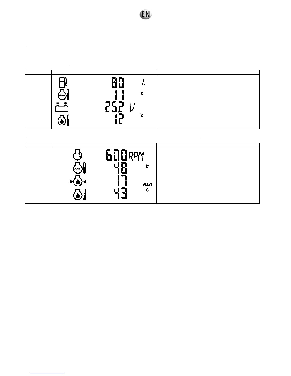
6.2.1.5. Description of the pictograms in zone 3
Pictograms in zone 3
All the pictograms in these zones are activated when TELYS is initialised. The pictograms below are given as examples.
Generating set stopped
Screen no. Pictograms Data displayed
P1
Fuel Level Indicator
Indication of Temperature of High Temperature coolant
(HT) (units according to settings menu)
Indication of Battery Voltage
Indication of Oil Temperature (units according to
settings menu)
Generating set start-up or generating set started or generating set switching off in progress
Screen no. Pictograms Data displayed
P2
Engine Speed Indication
Indication of Temperature of High Temperature coolant
(units according to settings menu)
Indication of Oil Pressure (units according to settings)
Indication of Oil Temperature (units according to
settings menu)
40/285

Generating set started
Screen no. Pictograms Data displayed
P3
Default
screen in
operation
Fuel Level Indicator
Alternator composite Voltage Indicator
Total Active Power Indicator
Alternator Frequency Indicator
P4
U12 Alternator composite Voltage Indicator
U23 Alternator composite Voltage Indicator
U31 Alternator composite Voltage Indicator
Alternator Frequency Indicator
P5
V1 Alternator single Voltage Indicator
V2 Alternator single Voltage Indicator
V3 Alternator single Voltage Indicator
Alternator Frequency Indicator
P6
U12 Alternator composite Voltage Indicator
V2 Alternator single Voltage Indicator
V1 Alternator single Voltage Indicator
Alternator Frequency Indicator
P7
V1 Alternator single Voltage Indicator
Single phase Alternator current indicator
Alternator Frequency Indicator
41/285
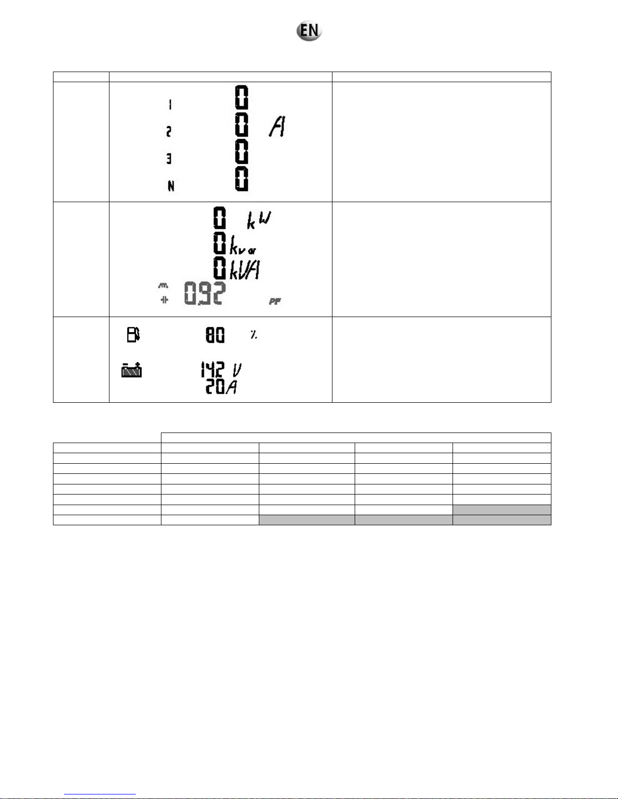
Screen no. Pictograms Data displayed
P8
Single phase Alternator current indicator
Two phase Alternator current indicator
Three phase Alternator current indicator
Neutral Alternator current indicator
P9
Total Active Power Indicator
Total Reactive Power Indicator
Total Effective Power Indicator
Total Power Factor Indicator (lagging or leading)
P10
Fuel Level Indicator
Indication of Battery Voltage
Indication of Battery Amps
Screen order of appearance according to network type with the generating set on.
Type of network
Order of appearance 3P+N 3P 2P+N 1P+N
1 P3 P3 P3 P3
2 P4 P4 P6 P7
3 P5 P8 P8 P9
4 P8 P9 P9 P2
5 P9 P2 P2 P10
6 P2 P10 P10
7 P10
Change screens by using the scrolling and selection wheel.
When the wheel is rotated clockwise, the screens scroll upwards and vice-versa.
The screens scroll in a loop.
E.g.: On three-phase + neutral network, then screen 7, then screen 1 and vice-versa.
42/285

6.2.1.6. Display of messages in zone 4
The display (zone 4), among other things, displays messages relating to the operation of the generating set. The messages are as
follows:
Initialisation of TELYS
Screen no. Screen Data displayed
G 1
Initialisation of TELYS when the power is switched on
and/or when loading a configuration
G 2
SERIAL No.: 08030010000
SOFTWARE: 6.1.0
NOMINAL VOLTAGE: 400V
FREQUENCY: 50Hz
NOMINAL KW: 320kW
EARTH SYSTEM: TNS
Generating set serial no.
Software version of TELYS
Alternator Nominal Voltage
Alternator Nominal Frequency
Nominal Active Output
Neutral Point
Bar graph indicating the display delay of the screen
43/285
Generating set stopped
Screen no. Screen Data displayed
G 3
OPERATION
MANUAL
Press START
to start
24/08/2005 13:12
Operating mode - generating set in Manual Mode ready to
start
Date and time (depending on settings)
G 4
OPERATION
AUTO
WARNING
START-UP POSSIBLE
IMMEDIATELY
24/08/2005 13:12
Operating mode - generating set in Auto Mode ready to
start
Date and time (depending on settings)
G 5
WARNING
AUTOMATIC Start
19 min 30 sec
24/08/2005 13:12
Operating mode - generating set in Auto Mode with
programmed start
Countdown to micro disconnection delay or EJP notice
delay (for France only)
Date and time (depending on settings)
Generating set start-up
Screen no. Screen Data displa
y
ed
G 6
START-UP
IN PROGRESS
24/08/2005 13:12
Operating phase - generating set in starting phase
Date and time (depending on settings)
G 7
AIR PREHEATING
10 seconds
24/08/2005 13:12
Operating phase - air preheating prior to starting generating
set
Countdown for air preheating delay
Date and time (depending on settings)
44/285

Generating set started
Screen no. Screen Data displayed
G 8
Default
screen
AVAILABLE POWER
75%
24/08/2005 13:12
Operating phase – generating set in operation – stable
voltage and frequency
Available power
Date and time (depending on settings)
G 9
AUTOMATIC STOP
IN PROGRESS
LOAD SUPPRESSION
1 min 30 sec
24/08/2005 13:12
Operating mode - operation in Auto Mode
Opening of power supply device (motorised circuit breaker
or source changeover switch controlled by TELYS)
Countdown for the mains return delay OR the load test
delay
Date and time (depending on settings)
G 10
AUTOMATIC STOP
IN PROGRESS
COOLING DOWN
1 min 30 sec
24/08/2005 13:14
Operating mode - operation in Auto Mode
Generation set cooling in progress
Countdown for Engine Stop delay (cooling) OR Gradual
Stop delay (Coolant temperature) OR Overload Gradual
Stop delay OR OFF load test delay
Date and time (depending on settings)
Generating setstop
Screen no. Screen Data displayed
G 11
OFF
IN PROGRESS
24/08/2005 13:16
Generating set stop in progress
Date and time (depending on settings)
45/285
Operating mode changeover (switching from Manual Mode to Auto Mode following auto start demand)
Screen no. Screen Data displayed
G 12
Start Demand
AUTO
Do you wish to change
to Auto Mode?
WARNING
Immediate start
OK Esc
Operating mode - operation in Manual Mode
AUTOMATIC start demand
Generating set stop request due to fault or by pressing STOP in Auto Mode
Screen no. Screen Data displayed
G 13
Manual Mode
activated
Do you wish to change
to AUTO mode?
OK Esc
Operating mode - operation in Auto Mode (generating set in
operation)
Warning message for switching to Manual Mode after the
STOP button has been pressed or a fault has appeared
46/285
6.2.2 Starting
Check that the generating set circuit breaker has triggered.
Danger
Connect the generating set battery
Turn the key switch to the ON position (without forcing it to the ON position), the ON lamp will light up (if the lamp does not light
up, check and replace the fuse if necessary)
Test the Alarm and Fault LEDs (menu 15 – TEST LAMPS)
1 ACTIONS
1/5
11 MANUAL <> AUTO
12 CONTROL LOAD
13 TEST GENERATING SET
14 PROGRAMS
15 TEST LAMPS
12 OK Esc
Press "Esc" several times to return to the following home menu
OPERATION
MANUAL
Press START
to start
24/08/2005 13:12
Check the battery voltage
Press START:
AIR PREHEATING
10 seconds
24/08/2005 13:12
If the engine is equipped with an air
preheating system, there is a delay
(adjustable) before the engine starts
(preheating activation period).
If the motor is not fitted with an air
preheating system or once the
preheating delay has elapsed, the
engine starts up (start of a cycle
comprising 3 attempts to start up the
engine).
START-UP
IN PROGRESS
24/08/2005 13:12
Warning: the number of successive and
automatic starting attempts is limited to 3.
The following pictogram will flash
AVAILABLE POWER
100.0%
24/08/2005 13:12
The following pictogram is displayed
The following information is displayed
Speed of rotation
Coolant temperature
Options
Oil pressure
Oil Temperature
47/285
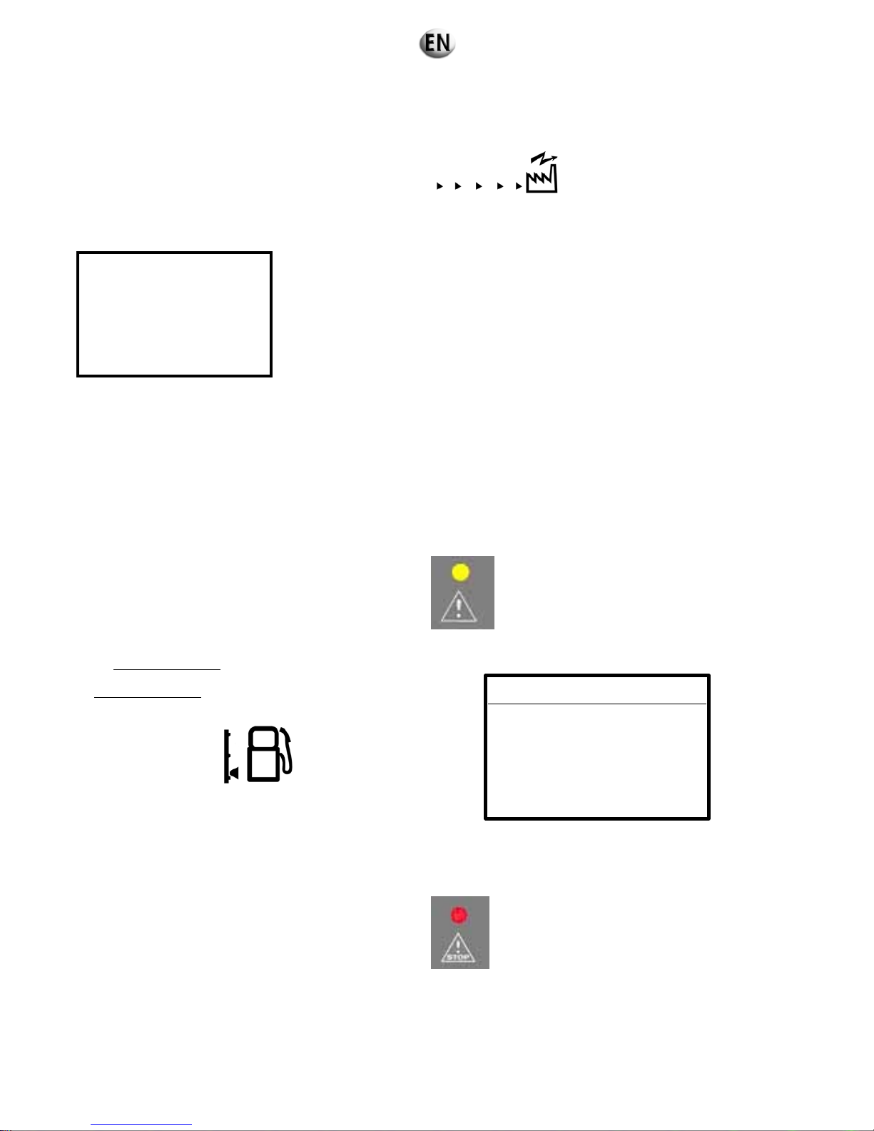
6.2.3 Switching off
Open the circuit breaker
manually OR by selecting menu 12 "CONTROL LOAD"
The following display will disappear (supply stopped)
Press the STOP button
The following screen is displayed and the generating set will stop
OFF
IN PROGRESS
24/08/2005 13:12
Switch TELYS off by turning the key to "OFF" (without forcing it to the "OFF" position).
6.2.4 Alarms and faults
6.2.4.1. Viewing alarms and faults
Alarms and faults are displayed as follows:
Alarms
All alarms will cause:
the yellow LED to flash "General alarm".
In conjunction with this LED:
a flashing pictogram appears on the LCD screen
representing the circuit affected by the alarm and the
associated indicator, if present
(example)
message on graphic display (example)
FAULT
ALARM
Low Fuel Level
25/12/05 15:30
OK=HELP
Faults
All faults will cause:
the generating set to stop: immediate or gradual stop (coolant temperature and overload or short circuit)
the red LED to flash "General fault".
48/285

In conjunction with this LED:
a flashing pictogram appears on the LCD screen
representing the
circuit affected by the fault and the
associated indicator, if present
(example)
message on graphic display (example)
FAULT
FAULT
Oil Pressure
25/12/05 15:30
OK=HELP
Faults have priority over alarms. Faults are displayed in the descending order of their appearance (from the most recent to the
oldest).
6.2.4.2. Activation of an alarm or fault
The appearance of an alarm o
r
a fault causes the corresponding screen to be displayed (examples below)
FAULT
ALARM
Low coolant Level
06/10/06 10:30
OK=HELP
FAULT
FAULT
Emergency Stop
06/10/06 15:30
Esc=RESET OK=HELP
Press OK (on the scrolling and selection wheel) to access the help message if it is available (example below)
HELP
Check the level
fuel
Esc=EXIT
If the alarm is no longer active, it is reset automatically (cause disappears).
Press Esc to reset a fault:
- reset acknowledged if the cause of the fault has been removed
- reset not performed if the cause of the fault is still present.
49/285

6.2.4.3. Activation of an alarm and a fault
The appearance of an alarm and a fault causes:
The yellow and red LEDs to flash
the related screen to be displayed (example below)
FAULTS 1/2
FAULT
Emergency Stop
25/12/05 15:30
Esc=RESET OK=LIST
If several faults are present, the number of faults is displayed at
the top of the screen.
The faults list can be accessed by pressing OK (of the scrolling and selection wheel) (examples below)
FAULTS
1/2
FAULT 25/12/05 15:30
Emergency Stop
ALARM 25/12/05 15:30
Low Fuel Level
12
OK=HELP Esc
Press Esc to return to the previous screen.
Press OK to go to the HELP screen (help on the highlighted
fault)
Use the scrolling and selection wheel to scroll through the list of
faults.
HELP
Check:
- Emerg. Stop Pos.
- Connector(s)
Esc
If the alarm is no longer active, it is reset automatically (cause disappears).
Press Esc to reset a fault:
- reset acknowledged if the cause of the fault has been removed
- reset not performed if the cause of the fault is still present.
50/285

6.2.4.4. Engine fault codes display
Certain alarms and engine faults generate specific fault codes. These codes are standardised according to the J1939 and/or J1587
standards, except for MTU engines that have a specific transmission protocol (see appendix, if applicable).
Terminology used by the SAE CAN J1939 standard
SPN: Suspect Parameter
Number
This represents the system or component at fault, for example: SPN 100, indicates an oil
pressure problem or a problem with the oil pressure sensor.
FMI: Failure Mode identifier
This represents the type of fault that has occurred. This may be an electrical, mechanical or
equipment fault.
Terminology used by VOLVO
SID: System Identifier
This term, used in the J1587 standard, has an equivalent in the J1939 standard (SPN).
However, this term corresponds, more particularly, to an assembly of components, for
example, the injection system.
PID: Parameter Identifier
This term, used in the J1587 standard, has an equivalent in the J1939 standard (SPN).
However, this term corresponds, more particularly, to a specific component, for example, a
sensor.
PPID: Parameter Identifier
This term, used in the J1587 standard, has an equivalent in the J1939 standard (SPN).
PPID corresponds to PID, but is only used by VOLVO.
FMI: Failure Mode identifier
This represents the type of fault that has occurred. This may be an electrical, mechanical or
equipment fault. VOLVO uses a SID-FMI or PID-FMI or PPID-FMI combination.
Terminology used by PERKINS
CID: Component parameter This term used by PERKINS has an equivalent in the J1939 standard (SPN).
FMI: Failure Mode identifier
This represents the type of fault that has occurred. This may be an electrical, mechanical or
equipment fault.
Terminology used by JOHN DEERE
SPN: Suspect Parameter
Number
This represents the system or component at fault, for example: SPN 100, indicates an oil
pressure problem or a problem with the oil pressure sensor.
FMI: Failure Mode identifier
This represents the type of fault that has occurred. This may be an electrical, mechanical or
equipment fault.
Terminology used by MTU
Displaying faults
The ADEC and MDEC general system faults are indicated on the equipment in the following
way: fault code numbers (generated by the ECU - Engine control unit).
51/285
In the event of a fault, the screen will display the following message:
FAULT
ALARM
ENGINE GENERAL 110 18
25/12/2005 15:30
OK=HELP
Engine fault code
.
Pressing OK will display fault finding information.
In addition, appendix D indicate the meaning of the code. The
checking and maintenance operations to carry out in order to
solve the fault are included in the user and maintenance
manuals of the engines supplied with the generating set
documentation.
For JOHN DEERE (JD), PERKINS (PE) and VOLVO (VO) engines, the codes displayed are SPN and FMI codes.
6.2.4.5. Horn reset
Depending on the settings made (menu 363 - HORN), the activation of an alarm and/or a fault leads to the horn sounding and the
following screen appearing:
HORN STOP
PRESS OK
25/12/2005 15:30
This screen will display first any messages relating to the
alarms and faults that appear as soon as OK is pressed.
52/285

6.3. Generator set with KERYS control panel
6.3.1 Presentation of the KERYS
The MICS Kerys system consists of a set of electronic modules in which each module performs a specific function..
These modules are interconnected according to a very precise architecture and exchange data to allow the following: the
command, control, regulation and protection of one or more generating sets according to multiple configurations.
The configurations range from the so-called “solo” generating set, with or without source inverter, to generating sets coupled to
each other, enabling electrical power plants to be created that can be coupled to one or more distribution grids in low voltage (LV)
and medium voltage (MV).
The MICS Kerys system consists of the following modules:
• man/machine interface module, also called MMI module,
• base module (heart of the system),
• regulation module,
• protection module,
• logic input/output module,
• analogue input/output module,
• temperature input module.
For the operation of a generating set in the smallest possible architecture, at least the following elements will be found:
• a man/machine interface module,
• a base module,
• a regulation module.
6.3.1.1. Operating conditions
Operating temperatures: - 20 °C + 70 °C
Storage temperatures: - 20 °C + 70 °C
Relative humidity during operation: 10 % to 95 % without condensation
according to IEC 1131-2 and equivalent UL/CSA
Relative humidity during storage: 5 % to 95% without condensation
according to IEC 1131-2 and equivalent UL/CSA
Height: 2,000 m during operation (Transfer 3,000 m)
Degree of protection: - Outside cabinet: IP54 (front of MMI modules).
- Inside cabinet: IP20 (BASE, ESTOR, ESANA, ETEMP, back of the
MMI).
Mechanical strength: Free falls (with packing), 5 random falls of:
1 m if p< 10 kg
0.5 m from 10 to 40 kg
0.25 m >40 kg
53/285

6.3.1.2. Conformity to legal and regulatory requirements
The various components of the system comply with the following standards:
Requirements specific to programmable controllers:
(Functional characteristics, immunity, robustness, safety, etc.)
EN 61131-1/2/3 (IEC 1131-2, IEC 664), EN61326,
CSA 22-2,
UL508.
Compliance with European directives (low voltage, electromagnetic compatibility, machinery). CE marking in
application of the safety requirements of standard EN 61131-2 – Programmable controllers, Part 2 – Equipment
requirements and tests.
To obtain the specific information prescribed by EN 61131-2, refer to the appropriate sections of that publication.
Electrical and self-extinguishability properties of insulating materials:
UL 746C,
UL 94.
Pollution degree: 2
Mechanical strength (details):
Vibration resistance: EN 61131-2 1994 (§2.1.3.2),
Frequency range: 10 - 57 Hz,
Continuous vibrations: 0.0375mm amplitude,
Occasional vibrations: 0.075mm amplitude.
Frequency range: 57Hz - 150Hz,
Continuous: 0.5 g constant acceleration,
Occasional: 1 g constant acceleration.
Complies with standard IEC 68-2-6, test Fc
Shock resistance
Occasional shocks: 15g, 11ms, semi-sinus.
Complies with standard IEC 68-2-27, test Fa
Emissions: Complies with standard EN55022 class A
Variation in supply voltage: EN61131-2 §6.3.7.3
Immunity:
Complies with standard IEC 61000-4-2: Electrostatic discharge: 4 kV for contact discharge, 8 kV for air discharge.
Complies with standard IEC 61000-4-3 Radiated field at 10V/m from 80MHz to 1GHz with sinusoidal modulation
AM 1kHz.
Complies with standard IEC 61000-4-4: Rapid transients in waves of 2 kV on power cables, 1 Kv on signal cables.
Complies with standard IEC 61000-4-5: Shock waves of 2 kV between wires and ground, 11 kV between wires for
the supplies and 1kV relative to ground for long signal circuits (lines from a
building or from a distance of over 30 m).
Complies with standard IEC 61000-4-6: Immunity to current injected at 3V from 150 kHz to 80 MHz (could be
increased to 10V).
Complies with standard IEC 61000-4-8: Immunity to the magnetic field at the grid frequency at 30 A/m.
54/285

6.3.2 Description of the KERYS
6.3.2.1. Identification of the hardware components
KERYS Tactil MMI module
MMI Module
P/N: 31613391001
Module item reference
D346000/B1
D346000: manufacturer product reference
B1: module hardware upgrade index
S/N: 1800
1800: serial number “not related” with a batch number
(1800 = the 1800
th
module manufactured since the start)
BATCH No.: 08/06
08: year of manufacture (year 2008)
06: week of manufacture (week 6)
Base module
Base module
P/N: 31613390901
Module item reference
D338000/B8
D338000: manufacturer product reference
B8: Module hardware upgrade index
S/N: 3491
3491: serial number “not related” with a batch number
(3491 = the 3491st module manufactured since the start)
BATCH No.: 07/45
07: year of manufacture (year 2007)
45: week of manufacture (week 45)
55/285
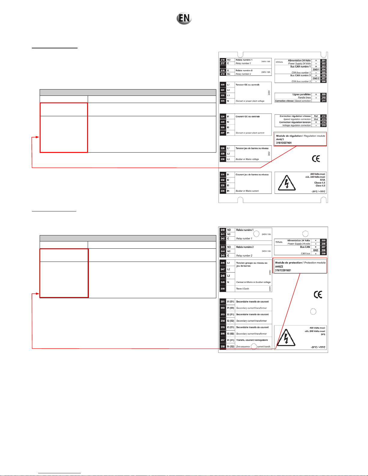
Regulation module
Regulation module
31613391501
Module item reference
A44Z1-G
A44Z1: manufacturer product reference
G: “main” module hardware upgrade index
0408A519
04: week of manufacture (week 4)
08: year of manufacture (year 2008)
A: “secondary” module hardware upgrade index
519: serial number “related” with a batch number (*)
(519 = the 519
th
module manufactured in week 04 of
the year 2008)
(*) i.e. a maximum of 999 modules that can be related with a batch number.
Protection module
Protection module
31613391601
Module item reference
A44Z2-E
A44Z2: manufacturer product reference
E : “main” module hardware upgrade index
4307A035
43: week of manufacture (week 43)
07: year of manufacture (year 2007)
A: “secondary” module hardware upgrade index
035: serial number “related” with a batch number (*)
(035 = the 35
th
module manufactured in week 04 of
the year 2008)
(*) i.e. a maximum of 999 modules that can be related with a batch number.
56/285

Logical inputs and outputs module
Logical inputs and outputs module (ESTOR –Binary inputs and outputs)
P/N :
31613391201
Module item reference
D341000/B1
D341000: manufacturer product reference
B1: module hardware upgrade index
S/N: 0250
0250: serial number “not related” with a batch number
(0250 = le 250
th
module manufactured since the start)
Batch No.: 06/49
06: year of manufacture (year 2006)
49: week of manufacture (week 49)
Analogue inputs and outputs module
Analogue inputs and outputs module (ESANA)
P/N:
31613391301
Module item reference
D343000/B1
D343000: Manufacturer product reference
B1: module hardware upgrade index
S/N: 0200
0200: serial number “not related” with a batch number
(0200 = the 200th module manufactured since the start)
BATCH No.:
06/49
06: year of manufacture (year 2006)
49: week of manufacture (week 49)
Temperature inputs module
Temperature inputs module (ETEMP)
P/N:
31613391401
Module item reference
D344000/B1
D344000: manufacturer product reference
B1: module hardware upgrade index
S/N: 0150
0150: serial number “not related” with a batch number
(0150 = the 150
th
module manufactured since the start)
BATCH No.:
06/49
06: year of manufacture (year 2006)
49: week of manufacture (week 49)
57/285

6.3.2.2. Identification of the software components
Only the components base module, MMI module, regulation module and protection module have embedded software.
”Software version” is referred to in order to identify a program implemented in one of the components.
V1.05c1
V
: as software version
1.05 : is the revision, which is a combination of 3 digits
c : main revision index
1 : secondary revision index used for specific projects
2007_02_12
Date of software version in English (year, month, day).
For a modification of a software version during the life of one of the products
(developments, corrections, etc.), the new software version implemented will be
entered by hand in a space reserved for this. The old software version will then be
deleted.
factory soft version
V
1.05c 2007 02 12
Location of the version labels
MMI
Base module
Regulation module Protection module
factory soft version
V
1.05c 2007 02 12
factory soft version
V
1.05c 2007 02 12
factory soft version
V
1.05c 2007 02 12
factory soft version
V
1.05c 2007 02 12
58/285

6.3.3 Description of the Man Machine Interface (IHM/MMI)
6.3.3.1. The Man Machine Interface
Display
The display has the following specifications:
7-inch colour TFT display, 16/9, 65536 colours
dimensions: 154 mm x 86 mm
neon backlighting
480 x 234 resolution
touch panel (8 columns x 8 rows).
Signalling control
keys
Operating buttons of the
generating set
Backlit display with touch-sensitive keypad
Alphanumeric keypad
Navigation keys
M.M.I. operation LED
(flashing)
59/285

The generating set operational keys
1 Manual mode selection. The illuminated led indicates that the mode is active
2 Selecting stop mode. The illuminated led indicates that the mode is active
3 Automatic mode selection. The illuminated led indicates that the mode is active
4 Test in progress LED.
5 In auto mode: test sequence control (off load test / load test) (*)
In manual mode: engine start-up and stop
6 Generating set circuit breaker opening control
7 Led indicating that generating set circuit breaker is open
8 Grid circuit breaker opening control
9 Led indicating that grid circuit breaker is open
10 Grid circuit breaker closing control
11 Led indicating that grid circuit breaker is closed
12 Led indicating the presence of grid voltage
13 Led indicating that grid circuit breaker is closed
14 Closing control for generating set circuit breaker
15 Led indicating the presence of generating set voltage
(*) The test request brings up a screen which offers a choice between “load test” and “off load test”.
The signalling control keys
The
key clears the faults.
The
key stops the buzzer.
The
key commands testing of the LED’s on the front of the MMI.
3
2
1
4
5
678
10
9
11
12
15
14
13
60/285

The navigation keys
It is also possible to navigate through the menus using the keypad.
It is possible to gain direct access to a menu by pressing the numerical key corresponding to its name.
The alphanumeric keys
They allow alphanumeric input by successive pressing of the keys. The characters entered appear in the order they were typed on
the keypad.
Move to the right
Move up
Move down
Confirm function of selected key
Return to upper level or escape for
the dialogue boxes
Move to the left
61/285

6.3.3.2. Navigation in the screens
There are three types:
the home screen,
the navigation screens,
the operation and configuration screens.
Home screen
This screen is the entry point to the system. It enables the main functions of the navigation to be accessed.
15/10/03 19:10 :00 GS 1 Home Auto Faults Alarms
- 1 -
Operation
- 6 -
System
- 2 -
Fault finding
- 5 -
Configuration
- 3 -
Archiving/Metering
-4 -
Maintenance
Navigation screens
These screens enable the various sub-menus to be accessed.
15/07/09 19:10 :00 GS 1 System Auto Faults Alarms
- 0 -
Welcome
- 1 -
Operation
- 2 -
Function keys
- 7 -
User adjustments
- 3 -
Synchro. column
- 6 -
Alarms & Faults
- 4 -
Central measurements
summary
- 5 -
Measurements
When a key is selected the lower level sub-menu appears if available or the allocated operation screen.
A sub-menu can also be accessed by pressing the corresponding key.
E.g.: by pressing key “1” on the alphanumeric keypad, you can directly access the "Operation” screen.
Title of the active menu Upper level
Lower levels
62/285
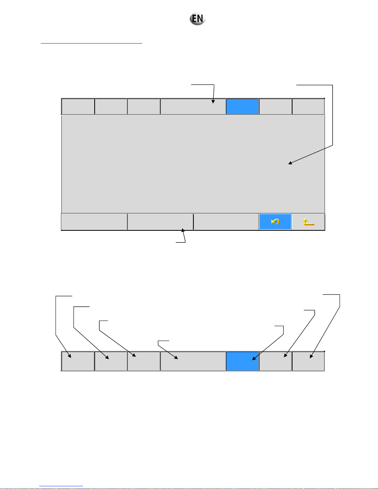
The operating and configuration screens
These screens bring up the information and commands relating to the active menu.
They are divided into three zones:
an upper band common to all types of screens.
the central section in which the specific information on the selected menu appears.
a lower band.
15/07/09 19:10 :00 GS 1 Event archive Auto Faults Alarms
- 1 -
Electrical archive
- 2 -
Mechanical archive
-3 –
Event metering
Upper band
Indications
15/07/09 19:10 :00 GS 1 Welcome Auto Faults Alarms
Upper band
Central section
Lower band
Date of the system
Time of the system
Reference of the GS with
which the M.M.I. dialogues
Indication of the presence of a fault on the GS
concerned (flashing red)
Indication of the presence of an alarm on the GS
concerned (orange flashing)
Indication of the operating mode of the
GS concerned
Name of the active screen
63/285
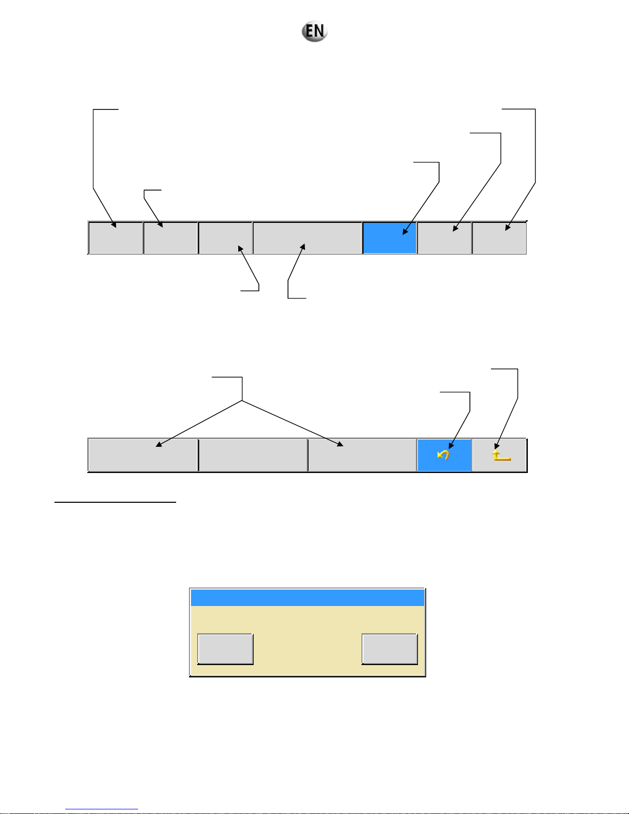
Controls
15/07/09 19:10 :00 GS 1 Welcome Auto Faults Alarms
Lower band
- 1 -
Function keys
- 2 -
Synchro. column
- 3 –
Measurements
The registration dialogue box
The registration dialogue boxes
To facilitate the entry of the information (parameters, texts), there are special screens, called “dialogue boxes”, which appear when
the need arises.
Confirmation of an entry in a menu
After the modification of a value in a menu the following dialogue box appears:
Validation
Validation of data entered
Valid Esc.
The confirmation key “Valid” saves the modification, the escape key “Esc.” cancels the modification.
Access to the regional parameters screen
Access to the regional parameters screen
Access to the “Drive” or “TOR
variables” screen
Access to the “Alarms and Faults” screen
Access to the “Alarms and Faults” screen
When configured in power plant with
switches, displays a dialogue box
enabling you to select the generating
set to which you want to be connected
1st action: access to the home screen
2nd action: return to the menu previously
selected (before first pressing
the button)
Return to the last active
operating screen
Return to the navigator menu
One or more shortcut keys to
the functions associated with
the active screen
64/285

Entry of a text
Title configuration
CDE AERO
Insert Copy Paste
Valid Delete title Delete a character Esc.
You move within the text using the “right” or “left” arrows on the keypad.
The characters are entered by means of the alphanumeric keys on the keypad.
Entering numerical values
The heading of the box provides information on the type of value entered, its unit and the variable concerned.
These indications are linked to the type of modified parameter.
Time in 1/10 second (6000)
0<= 0000 <=9999
Valid Esc.
Saves the changes and closes the dialogue box
Deletes the entire text
Deletes the letter shown by the cursor
Closes the menu without saving the changes
Name of the modified function
Text to be modified or created
Inserts a space to the left of the cursor
Saves the modifications and closes the screen
If it exists, indicates the lowest possible value
If it exists, indicates the highest possible value
Closes the screen without saving the modifications
65/285

Selecting from a list
The box heading indicates the parameter which will be assigned from your selection.
Type of fault (6000)
Whithout
General
Alarm
Valid Esc.
Saving changes
After changing a parameter, the new data is stored in volatile memory, which means that in the event of a power failure, any
changes will be lost. It is also necessary to transfer these values to permanent memory. This is the “Save in flash” operation.
Following a modification a red “Sauvegarde à faire” (Save) indicator light flashes at the top left of the screen. Pressing this indicator
light brings up one of the following dialogue boxes:
Save in flash
Valid Esc.
Save in flash
Custome
r
3
Factory
Valid Esc.
Always select “Client”
Pressing “Valid” confirms the operation, pressing “Esc.” cancels it.
List indicating possible selections
Arrows for moving the cursor
Active selection
Arrows only visible if the number of choices
does not fit on the screen
(enables you to go to the next page on the list
or return to the previous page on the list)
66/285

During saving, the following screen indicates that the operation in is progress:
6.3.4 Configurations
6.3.4.1. Operating principle
The operational modes are as follows:
SOLO
Genset
Without
coupling to
grid
With coupling
to grid
- Operation of a single genset without coupling.
- Normal/emergency switch (NES) not controlled by Kerys.
Without N/E
switch
(A612)
Temporary
coupling
(A651)
Power plant
Without
coupling to
grid
Without N/E
switch
(A633)
- Automatic operation of a single genset.
- Temporary coupling on grid return following interruption.
Without N/E
switch
(A632)
- Operation of a power plant without coupling to grid.
- Normal/emergency switch (NES) not controlled by Kerys.
- Power plant gensets interconnected by parallel lines.
- Operation of a power plant without coupling to grid.
- Normal/ermegency switch (NES) not controlled by Kerys.
- Power plant genset interconnected by CAN.
Note:
Without coupling: the switch is equipped with electrical and mechanical interlocking.
With coupling: the switch is not equipped with an electrical and mechanical interlock.
Saving in flash…
67/285

6.3.4.2. Legends
M
Electrically controlled circuit breaker
AB
Exchange of information from A to B and from B to A
Transmission of information from A to B only
3 PH ”Current” information, 3 PH = 3 phases
3 PH + N ”Voltage” information, 3 PH + N = 3 Phases + Neutral
6.3.4.3. Configuration in solo generating set
Without Normal/Emergency inverter (A612)
This configuration is designed to provide:
The generation of electricity for an installation from an external starting command (dry contact).
The generation of electricity for an installation in forced operation.
Regulation
module
Base
module
C
A
N
B
u
s
E
t
h
e
r
n
e
t
3PH + N
3PH
M
MMI module
Application (load)
Automatic operation (Kerys in “AUTO” mode)
Loss of grid voltage
• Generating set start request (dry contact, switch, clock, etc.).
• The speed and voltage of the generating set increase.
• Generating set power unit switched off after voltage and frequency stabilisation.
Return of grid voltage
•
Dry contact, switch, clock, etc. switched on.
• Cooling delay.
• Generating set stopped and set to standby.
68/285

FORCED OPERATION (Kerys in “AUTO” mode)
Start of FORCED OPERATION
• Generating set start request (dry contact, switch, clock, etc.).
• The speed and voltage of the generating set increase.
• Generating set power unit switched off after voltage and frequency stabilisation.
The installation is supplied by the generating set
End of FORCED OPERATION
• Dry contact, switch, clock, etc. switched on.
• Generating set power unit switched on.
• Cooling delay.
• Generating set stopped and set to standby.
The Kerys remains in ”AUTO” mode
Manual operation of generating set
This mode of operation is selected with the “MANU” key (on the front of the MMI module). The operator is able to start and stop the
generating set by using the MMI keypad. The generating set power unit is switched off by means of the MMI keys. The safety
devices of the generating set remain active in this mode of operation.
This mode of operation is the responsibility of the operator.
Temporary coupling to the grid (A651)
This configuration is designed to provide:
Emergency electricity supply to an installation following a grid loss. Return to the grid is achieved by a temporary coupling
with transfer of the generating set load to the grid.
FORCED OPERATION with a generating set.
Temporary coupling for “Effacement Jour de Pointe” (EJP)* mode or other rates (Information transmitted by dry contacts).
Regulation
module
Base
module
C
A
N
b
u
s
E
t
h
e
r
n
e
t
3PH + N
3PH
3PH
3PH
M
M
M
Optional
manual or
motorised
circuit
breaker
MMI Module
Application
(load)
Grid
* the “EJP” (Peak Day Load Shedding) system is specific to the French power grid.
69/285

Automatic operation (Kerys in “AUTO” mode) (temporary “grid return” coupling)
Loss of grid voltage
•
Adjustable grid loss acquisition delay (controlled by the Kerys or by a mains detection module).
• Generating set start request.
•
The speed and voltage of the generating set increase.
• Power unit switched on, grid side.
•
Generating set power unit switched off after voltage and frequency stabilisation.
Return of grid voltage
•
Adjustable grid return acquisition delay (controlled by the Kerys or by a mains detection module).
• Synchronisation of the generating set to the grid.
• After synchronisation, the grid power unit is switched off.
• Transfer of the active and reactive power of the generating set to the grid according to a predetermined ramp. The ramp
does not exceed 10 seconds for transfer of the generating set’s rated output. The generating set power unit is disconnected
when the power on the generating set reaches the lower limit.
• Generating set power unit switched on.
• Cooling delay.
• Generating set stopped and set to standby.
The Kerys remains in “AUTO” mode
FORCED OPERATION (Kerys in “AUTO” mode)
(temporary outward and return coupling)
Start of FORCED OPERATION
• Generating set start request.
• The generating set voltage and speed increase.
• When the generating set is stabilised in speed and voltage, synchronisation of the generating set to the grid is requested.
• After synchronisation, the generating set power unit is switched off.
• Transfer of the active and reactive power from the grid to the generating set according to a predetermined ramp. The ramp
does not exceed 10 seconds for transfer of the generating set’s rated output. The generating set power unit is disconnected
when the power on the generating set reaches the lower limit.
• Power unit switched on, grid side.
The installation is supplied by the generating set
End of FORCED OPERATION
•
Opening of the forced operation order.
• Synchronisation of the generating set to the grid.
•
Grid power unit switched off.
•
Transfer of the generating set’s active and reactive power to the grid.
• Generating set power unit switched on.
• Cooling delay.
• Generating set stopped and set to standby.
The Kerys remains in “AUTO” mode
The installation is supplied by the grid
Manual generating set operation
This mode of operation is selected with the “MANU” key. The operator is able to start and stop the generating set via the MMI
keypad. The power unit is switched off manually with the manual synchronisation of the generating set to the grid using the keys
“+ F”, “- F”, “+V”, “-V”, the load transfer remains automatic. The safety devices of the generating set remain active in this mode of
operation.
This mode of operation is the responsibility of the operator
70/285

6.3.4.4. Power plant configuration (Several generating sets in parallel)
Without common part and without Normal/Emergency inverter (A632)
This configuration is designed to provide:
Emergency electricity supply to an installation following a grid loss (The grid loss is not controlled by Kerys). Return to the
grid will be achieved by Normal / Emergency switchover by means of a self-driven inverter (not controlled by Kerys).
FORCED OPERATION with a generating set.
Operation in “Effacement Jour de Pointe” (EJP)* mode or other rates.(Information transmitted by dry contacts).
An active power regulation (speed of the generating sets) by parallel lines connected between all the regulation modules.
Regulation
module
Base
module
C
A
N
b
u
s
E
t
h
e
r
n
e
t
3PH + N
3PH
M
3PH
3PH
Regulation
module
Base
module
C
A
N
b
u
s
E
t
h
e
r
n
e
t
3PH + N
M
3PH
Genset 1
Genset 2
Genset x
Parallel line
(*) the “EJP” (Peak Day Load Shedding) system is specific to the French power grid.
Note 1: In this operating mode there is no reactive power regulation (generating set voltage); the generating sets are static.
Note 2: In an installation of the power station type (several generating sets in parallel) two modes of coupling between generating
sets are possible
• Coupling when stopped.
• Coupling in normal operation.
Principle of coupling when stopped
- all the generating set power units are switched off,
- starting of all the generating sets,
- when the speed reaches 1450 rpm, activated excitation command on all the generating sets,
- the voltage generated by each generating set increases gradually and the voltage is therefore the same in all
generating sets,
- the generating sets therefore reach 1500 rpm at 400 V 50 Hz.
At the end of global operation, if the power consumed by the installation does not require the operation of all the
generating sets within the power plant, one or more generating sets will be stopped according to the wattmetric control.
Restarting of the generating set (these generating sets) depends on the load and wattmetric control of the load.
However, if a generating set is reconnected to a busbar already subjected to a load, the “recoupling” is carried out in
normal operation and not when the generating set is stopped.
71/285
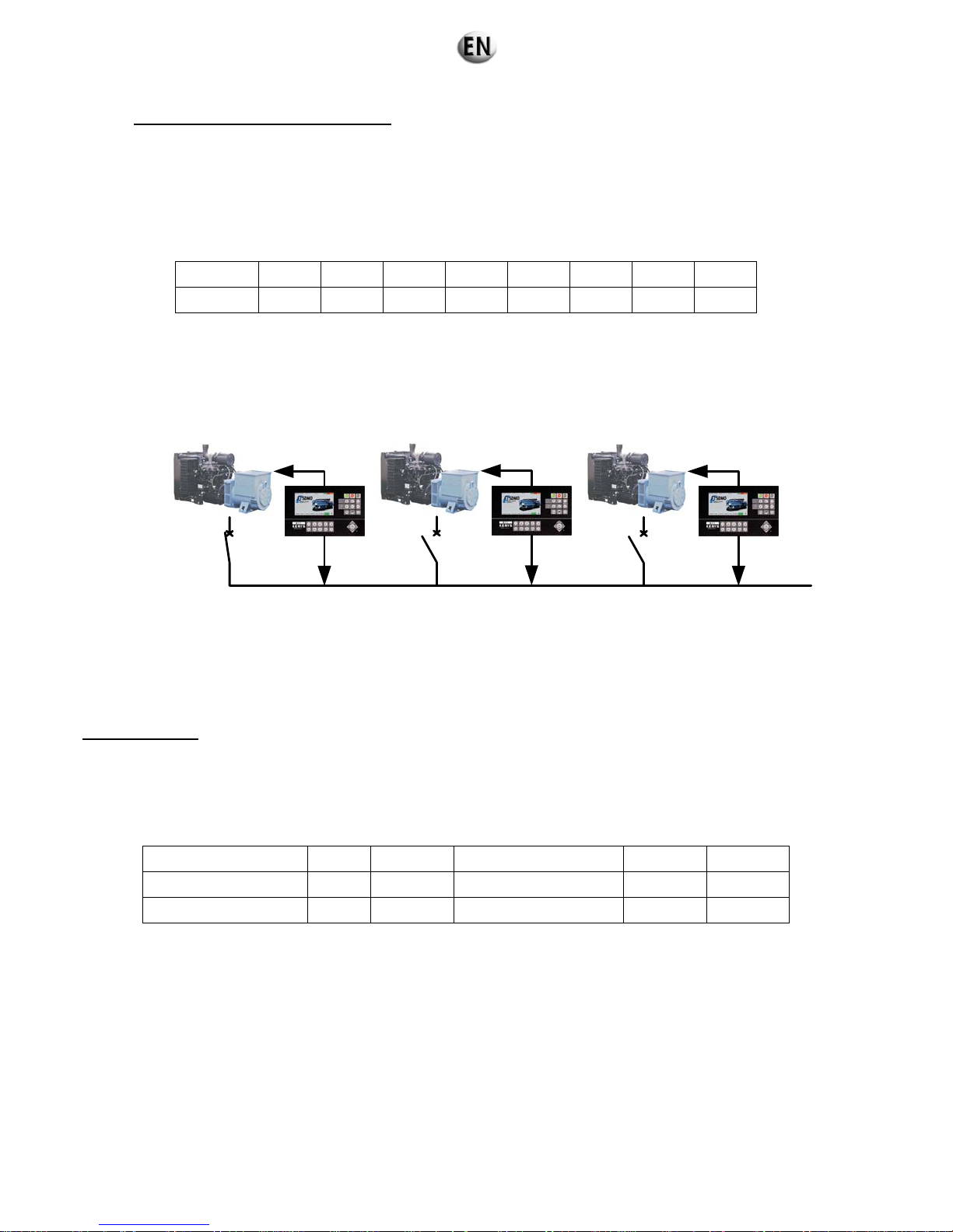
Principle of coupling in normal operation
Coupling in normal operation enables all the generating sets to be coupled (in voltage and frequency) to a busbar supplied
by a generating set designed as master at the output.
A number (1 to 15) is assigned to each Kerys. This number serves solely to establish the IP address of each Kerys for
communication by Ethernet and loading the programs.
A second number (from 1 to 15) is also assigned to each Kerys and defines the priority.
Example: let us assume a plant of 8 generating sets
Gen set 1 2 3 4 5 6 7 8
Priority 08 07 06 05 04 03 02 01
The numbers on the first line enable the IP address of each Kerys to be allocated. The numbers on the second line define
the priority.
Therefore Kerys no. 8 with priority 01 is considered to be the master generating set and closes its flow first. The other
generating sets then synchronise one by one to the central busbar, transmitting the information on voltage, frequency and
phase difference to this busbar (see sketch).
CB1
GS1
U1
CB2
GS2
U2
CB3
GS3
U3
Busbar U
Example for 3 GSs:
• DJ1 (Circuit breaker 1) is closed, the voltage is present on the busbar.
• Kerys 2 analyses the differences between U2 and U of the busbar before coupling.
• Kerys 3 analyses the differences between U3 and U of the busbar before coupling.
Each Kerys, independently of its neighbour, will close its discharge on the central busbar.
Wattmetric control
The wattmetric control is used when two generating sets are coupled. It provides optimum management of the number of
generating sets operating by constantly analysing the power required by the user.
Let us take the example of a power plant of 4 x 600 kW generating sets.
The threshold setting screen (1-7-3-3) supplies the following data:
Threshold 1 GS => 2 GS 75% 450 kW Threshold 2 GS => 1 GS 30 % 360 kW
Threshold 2 GS => 3 GS 75% 900 kW Threshold 3 GS => 2 GS 30 % 540 kW
Threshold 3 GS => 4 GS 75% 1350 kW Threshold 4 GS => 3 GS 30 % 720 kW
The maximum available power is 600 x 4 = 2400 kW. Assuming that a single generating set is operating, we will have the following
sequence in the case of linear progression of the load.
When the power required by the application reaches 75% of the power of the generating set in operation (GS at priority 01), i.e.
450 kW, the second GS (at priority 02) is started and is synchronised with GS 1. Its flow is then closed.
72/285

The second GS thus coupled initiates its power on ramp (adjustable delay) and the distribution of power among the two generating
sets takes place. Each generating set will then take 50% of the required power, i.e. 225 kW.
When the power required for the application reaches 75% of the power of the two generating sets in operation (GSs at priority 01
and 02), i.e. 900 kW, the third GS (at priority 03) is then started and is synchronised with GS1 and GS2. Its flow is then closed. The
third GS thus coupled initiates its power on ramp (adjustable delay), and the distribution of power among the three generating sets
takes place.
Each generating set will then take 33.33% of the required power, i.e. 300 kW, corresponding to 50% of its rated output (600 kW).
When the power required for the application reaches 75% of the power of the three GSs in operation (GSs at priority 01, 02 and
03), i.e. 1350 kW, the fourth GS (at priority 04) is then started and synchronised with GS1, GS2 and GS3. Its flow is then closed.
The fourth GS thus coupled initiates its power on ramp (adjustable delay) and the distribution of power among the four generating
sets takes place. Each generating set will then take 25% of the power required, i.e. 337.5 kW, corresponding to 56.25% of its rated
output (600 kW).
The power required for the application may continue to increase up to the upper plant limit (95%) of 2400 kW, i.e. 2280 kW
(the setting can be changed). This corresponds of course to the upper generating set limit, i.e. 570 kW (95% of 600 kW).
Automatic operation (All Kerys PLCs in “AUTO” mode) (coupling when stopped)
Loss of grid voltage
• Grid loss acquisition delay (controlled by the mains detection module).
• Generating set power units switched off.
• Generating set start request.
• The generating sets’ speed increases.
• Speed stabilisation delay.
• Order of excitation for each generating set at nominal speed; the voltage is then quickly established on the busbar.
• Start of distribution of active power.
• Resumption of use at the rated power and frequency.
Wattmetric control
This wattmetric control will be activated after a global operation delay. This global operation enables the application to be resumed
after power is restored to the different outputs, and ensures stability of the load before the wattmetric control is started.
Depending on the power for the application, the number of generating sets in production may vary in order to optimise the
production for consumption.
The procedure is as follows:
• End of the global operation delay.
• Start of analysis of the active power consumed.
Example: A generating set must be stopped according to the set thresholds.
• Power cut at the non-priority generating set, transfer of the power to the generating set(s) remaining in production.
• Uncoupling of the non-priority generating set, at zero power, by switching on the generating set power unit.
• Cooling delay.
• Generating set stopped and set to standby.
Example of increase in power:
• Generating set start request.
• The speed of the generating set increases.
• Alternator excitation, the generating set establishes its voltage.
• Request for synchronisation of the generating set to the busbar (i.e. the other coupled generating sets).
• Generating set power unit switched off.
Return of grid voltage
•
Grid return acquisition delay (controlled by the mains detection module).
• Generating set power units switched on.
• Cooling delay.
• Generating sets stopped and set to standby.
The Kerys PLCs remain in “AUTO” mode
73/285

FORCED OPERATION
Start of FORCED OPERATION
• Generating set power units switched off.
• Generating set start request.
• The generating sets increase in speed.
• Speed stabilisation delay.
• Order of excitation for each generating set at nominal speed; the voltage is then quickly established on the busbar.
• Start of active power distribution.
• Resumption of application at rated voltage and frequency.
The Kerys PLCs remain in “AUTO” mode
The installation is supplied by the generating sets
End of FORCED OPERATION
• Generating set power units switched on.
• Cooling delay.
• Generating sets stopped and set to standby.
The Kerys PLCs remain in “AUTO” mode
The installation is supplied by the grid
Manual power plant operation
This mode of operation is selected with the “MANU” key. This enables the operator to start and stop the generating sets one by one
via the MMI keypad. The generating set power unit is switched off manually with synchronisation of each generating set to the
busbar using the MMI keys “+F”, “-F”, “+V” and “-V”. The distribution of power among the generating sets remains automatic. The
safety devices of the generating sets remain active in this mode of operation.
This mode of operation is the responsibility of the operator.
Without common part and without Normal/Emergency inverter (A633)
This configuration is designed to provide:
Emergency electricity supply to an installation following a grid loss (The grid loss is not controlled by the Kerys).
Return to
the grid can be achieved via Normal / Emergency switchover with a self-driven inverter (not controlled by the Kerys).
FORCED OPERATION with a generating set.
Operation in “Effacement Jour de Pointe” (EJP)* mode or other rates. (Information transmitted by dry contacts).
Active power regulation (speed of the generating sets) by digital buses connected between all the regulation modules.
Regulation
module
Base
module
C
A
N
b
u
s
E
t
h
e
r
n
e
t
3PH + N
3PH
M
3PH
3PH
Regulation
module
Base
module
C
A
N
b
u
s
E
t
h
e
r
n
e
t
3PH + N
M
3PH
Genset 1
Genset 2
Genset x
Digital Bus
Digital Bus
(*) the “EJP” system is specific to the French power grid.
Note 1: In this operating mode active and reactive power is distributed by a digital bus between the regulation modules (voltage of
the generating sets).
Note 2: In an installation of the power plant type (several generating sets connected by digital bus), two modes of coupling
between generating sets are possible
• Coupling when stopped.
• Coupling in normal operation.
74/285

Principle of coupling when stopped
- all the generating set power units are switched off,
- starting of all the generating sets,
- when the speed reaches 1450 rpm, activated excitation command on all the generating sets,
- the voltage generated by each generating set increases gradually and the voltage is therefore the same in all
generating sets,
- the generating sets therefore reach 1500 rpm at 400 V 50 Hz.
At the end of global operation, if the power consumed by the installation does not require the operation of all the
generating sets within the power plant, one or more generating sets will be stopped according to the wattmetric control.
Restarting of the generating set (these generating sets) depends on the load and wattmetric control of the load.
However, if a generating set is reconnected to a busbar already subjected to a load, the “recoupling” is carried out in
normal operation and not when the generating set is stopped.
Principle of coupling in normal operation
Coupling in normal operation enables all the generating sets to be coupled (in voltage and frequency) to a busbar supplied
by a generating set designed as master at the output.
A number (1 to 15) is assigned to each Kerys. This number serves solely to establish the IP address of each Kerys for
communication by Ethernet and loading the programs.
A second number (from 1 to 15) is also assigned to each Kerys and defines the priority.
Example: let us assume a plant of 8 generating sets
Gen set 1 2 3 4 5 6 7 8
Priority 08 07 06 05 04 03 02 01
The numbers on the first line enable the IP address of each Kerys to be allocated. The numbers on the second line define
the priority.Therefore Kerys no. 8 with priority 01 is considered to be the master generating set and closes its flow first. The
other generating sets then synchronise one by one to the central busbar, transmitting the information on voltage, frequency
and phase difference to this busbar (see sketch).
CB1
GS1
U1
CB2
GS2
U2
CB3
GS3
U3
Busbar U
Example for 3 GSs:
• DJ1 (Circuit breaker 1) is closed, the voltage is present on the busbar.
• Kerys 2 analyses the differences between U2 and U of the busbar before coupling.
• Kerys 3 analyses the differences between U3 and U of the busbar before coupling.
Each Kerys, independently of its neighbour, will close its discharge on the central busbar.
75/285

Wattmetric control
The wattmetric control is used when two generating sets are coupled. It provides optimum management of the number of
generating sets operating by constantly analysing the power required by the user.
Let us take the example of a power plant of 4 x 600 kW generating sets.
The threshold setting screen (1-7-3-3) supplies the following data:
Threshold 1 GS => 2 GS 75% 450 kW Threshold 2 GS => 1 GS 30 % 360 kW
Threshold 2 GS => 3 GS 75% 900 kW Threshold 3 GS => 2 GS 30 % 540 kW
Threshold 3 GS => 4 GS 75% 1350 kW Threshold 4 GS => 3 GS 30 % 720 kW
The maximum available power is 600 x 4 = 2400 kW. Assuming that a single generating set is operating, we will have the following
sequence in the case of linear progression of the load.
When the power required by the application reaches 75% of the power of the generating set in operation (GS at priority 01), i.e.
450 kW, the second GS (at priority 02) is started and is synchronised with GS 1. Its flow is then closed.
The second GS thus coupled initiates its power on ramp (adjustable delay) and the distribution of power among the two generating
sets takes place. Each generating set will then take 50% of the required power, i.e. 225 kW.
When the power required for the application reaches 75% of the power of the two generating sets in operation (GSs at priority 01
and 02), i.e. 900 kW, the third GS (at priority 03) is then started and is synchronised with GS1 and GS2. Its flow is then closed. The
third GS thus coupled initiates its power on ramp (adjustable delay), and the distribution of power among the three generating sets
takes place.Each generating set will then take 33.33% of the required power, i.e. 300 kW, corresponding to 50% of its rated output
(600 kW).
When the power required for the application reaches 75% of the power of the three GSs in operation (GSs at priority 01, 02 and
03), i.e. 1350 kW, the fourth GS (at priority 04) is then started and synchronised with GS1, GS2 and GS3. Its flow is then closed.
The fourth GS thus coupled initiates its power on ramp (adjustable delay) and the distribution of power among the four generating
sets takes place. Each generating set will then take 25% of the power required, i.e. 337.5 kW, corresponding to 56.25% of its rated
output (600 kW).
The power required for the application may continue to increase up to the upper plant limit (95%) of 2400 kW, i.e. 2280 kW
(the setting can be changed).This corresponds of course to the upper generating set limit, i.e. 570 kW (95% of 600 kW).
Automatic operation (All Kerys PLCs in “AUTO” mode) (coupling when stopped)
Loss of grid voltage
•
Grid loss acquisition delay (controlled by the mains detection module).
• Generating set power units switched off.
• Generating set start request.
• The generating sets increase in speed.
• Speed stabilisation delay.
• Order of excitation for each generating set at nominal speed; the voltage is then quickly established on the busbar.
• Start of active power distribution.
• Resumption of application at rated voltage and frequency.
76/285

Wattmetric control
This wattmetric control will be activated after a global operation delay. This global operation enables the application to be resumed
after power is restored to the different outputs, and ensures stability of the load before the wattmetric control is started.
Depending on the power for the application, the number of generating sets in production may vary in order to optimise the
production to consumption.
The procedure is as follows:
• End of the global operation delay.
• Start of analysis of the active power consumed.
Example: A generating set must be stopped according to the set thresholds.
• Power cut at the non-priority generating set, transfer of the power to the generating set(s) remaining in production.
• Uncoupling of the non-priority generating set, at zero power, by switching on the generating set power unit.
• Cooling delay.
• Generating set stopped and set to standby.
Example of increase in power:
• Generating set start request.
• The generating set increases in speed.
• Alternator excitation, the generating set establishes its voltage.
• Request for synchronisation of the generating set to the bus bar (i.e. the other coupled generating sets).
• Generating set power unit switched off.
Return of grid voltage
• Grid return acquisition delay (controlled by the mains detection module).
• Generating set power units switched on.
• Cooling delay.
• Generating sets stopped and set to standby.
The Kerys PLCs remain in “AUTO” mode
FORCED OPERATION
Start of FORCED OPERATION
•
Generating set power units switched off.
• Generating set start request.
• The generating sets increase in speed.
• Speed stabilisation delay.
• Order of excitation for each generating set at nominal speed; the voltage is then quickly established on the busbar.
• Start of active power distribution.
• Resumption of application at rated voltage and frequency.
The Kerys PLCs remain in “AUTO” mode
The installation is supplied by the generating sets
End of FORCED OPERATION
• Generating set power units switched on.
• Cooling delay.
• Generating sets stopped and set to standby.
The Kerys PLCs remain in “AUTO” mode
The installation is supplied by the grid
Manual power plant operation
This mode of operation is selected with the “MANU” key. This enables the operator to start and stop the generating sets one by one
via the MMI keypad. The generating set power unit is switched off manually with synchronisation of each generating set to the
busbar using the MMI keys “+F”, “-F”, “+V” and “-V”. The distribution of power among the generating sets remains automatic.
The
safety devices of the generating sets remain active in this mode of operation.
This mode of operation is the responsibility of the operator.
77/285

6.3.5 Connections of the generating sets
6.3.5.1. Recommendations before the connections
Warning
Disconnect the battery cables before carrying out any work on the generating set.
To disconnect the battery disconnect the negative cable (-) first.
6.3.5.2. Connections according to the configurations
Solo generating set without inverter (A612)
Solo generating set, CRF coupling (A651)
Power plant without common part without inverter (A632)
Power plant without common part and without inverter
(A633)
Ground connection
X X
Ground connection box
X X
Facility power outlet
O O O O
Connecting cables between the generating sets (CAN BUS)
X
Connecting cables between the generating sets (Parallel line)
X
Power cables
X X X X
Customer terminal:
Remote operation
z z z z
External emergency stop
z z z z
EJP
z z z z
Switch grid detection
(1)
z
z z
Grid detection by regulation card
(1)
z
X
z z
Emergency N/E switch control
z
Emergency cutout
z
Normal N/E switch control
z
Summary of faults and alarms
z z z z
Generating set operation
z z z z
Generating set available in Auto
z z z z
X: to be connected O: if available
z: if necessary
(1)
Only one of the two grid detections needs to be cabled.
78/285
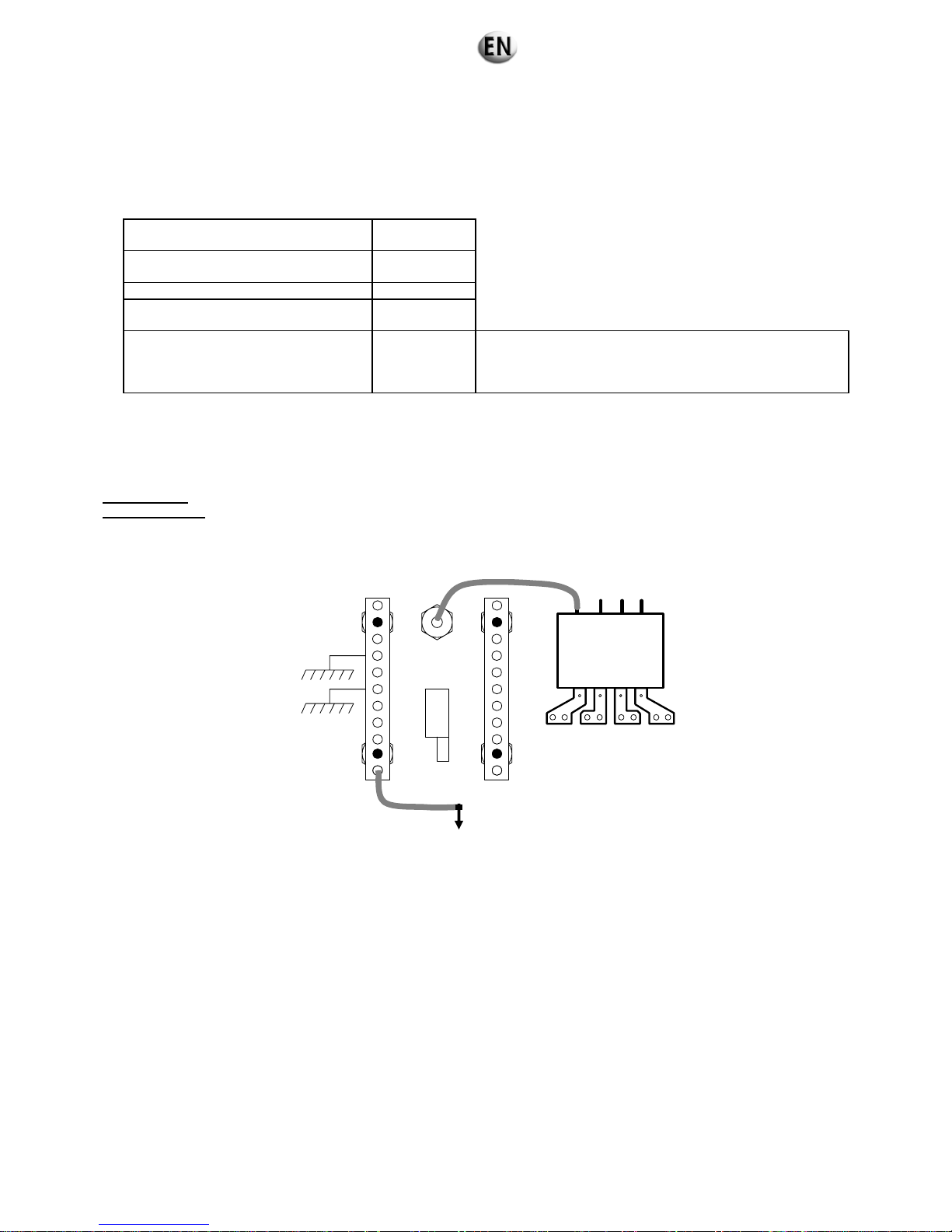
6.3.5.3. Earthing system (Standard only)
• The ground of the generating set must be connected to earth. To do so, use a copper cable (Green / Yellow), 25 mm² minimum
for a bare cable and 16 mm² for an insulated cable, connected to the earth of the generating set, and to a ground rod of
galvanised steel pushed vertically into the ground.
For a fault voltage of 25 V and a fault current of 30 mA.
Nature of the ground
Rod length (in
metres)
Rich arable land, moist compact hard
core
1
Poor arable land 1
Poor arable land, gravel, coarse hard
core
1
Stony bare soils, dry sand,
impermeable rocks
3.6
To obtain an equivalent length several ground rods can be
used connected in parallel and separated by at least their
length. Example: Four 1 metre rods interconnected and
separated by 1 metre respectively.
• Check the earthing connection before switching on the generating set.
• Check that the safety earthing system is working.
Single genset
Earthing system
: IT
Active isolation controller
DISJONCTEUR
N
R
ST
Ground
Ground rod
Interconnection
bar between
genset grounds
CIRCUIT
BREAKER
Current
transforme
r
Isolated neutral
79/285

Earthing system: TNS
Earthing system: TT
Active differential circuit breaker
Type of earthing system: EDF application (On rental generating set only)
Active differential circuit breaker
DISJONCTEUR
N
R
ST
Neutral
Ground
Ground rod
DISJONCTEUR
N
R
ST
Neutral
Ground
Ground rod
DISJONCTEUR
N
R
ST
Ground
Ground rod
Interconnection
bar between
genset grounds
Interconnection
bar between
genset grounds
Interconnection
bar between
genset grounds
CIRCUIT
BREAKER
Neutral connected to grounds
Current
transformer
Current
transformer
Current
transformer
CIRCUIT
BREAKER
CIRCUIT
BREAKER
80/285

Power plant
Connection of the generating sets to the box
One ground rod for one generating set power plant
Important
Genset 1
Genset 2
Ground rod
Neutral
Earth junction
box
GS1 current transformer
link
GS2 current transformer
link
GSX current transformer
link
1 current
transformer per GS
Genset x
Genset 2
Genset 1
Genset x
81/285

Earthing system: IT
Earthing system: TNS
Earthing system: TT
DISJONCTEUR
N
R
ST
Neutral connected to grounds
Ground
Ground rod
DISJONCTEUR
N
R
ST
Ground
Ground rod
DISJONCTEUR
N
R
ST
Neutral
Ground
Ground rod
Junction box
If equipped
CIRCUIT
BREAKER
CIRCUIT
BREAKER
CIRCUIT
BREAKER
Current
transformer
Current
transformer
Isolated neutral
Current
transformer
82/285

Connection of generating sets to client terminal boards
Reinsert the shunts of terminals 45 and 46 after having disconnected the current transformer from the
junction box.
Important
6.3.5.4. Facility power outlet
The facility power outlet (if fitted) provides the emergency supply to the generating set from an external electrical source. It enables
the different units (preheating, desk, etc.) to be powered without using their batteries.
44
45
42
43
40
41
38
39
36
37
34
35
32
33
30
31
28
29
464748
Xcbc3
44
45
42
43
40
41
38
39
36
37
34
35
32
33
30
31
28
29
464748
Xcbc3
Junction box
Remove the shunts at
terminals 45-48 and 46-47
83/285

6.3.5.5. Connecting cable between the generating sets (power plant)
The power cables and the generating set connecting cable may
intersect
Important
Rental application
The generating set power cables and connecting cable cannot
be placed in parallel less than 1 metre apart.
Important
The generating set power cables, the generating set connecting cable and the connections must be in
perfect condition. Replace them if necessary.
Important
Generating set 1
019x04
019x12
Generating set 2
019x04
019x12
2 generating sets
Generating set 1
019x04
019x12
Generating set 2
019x04 019x12
Generating set 3
019x04
019x12
Generating set x
019x04 019x12
3 or more generating sets
Connecting cable
Power cable
Connecting cable
Power cable
1 metre MIN.
84/285
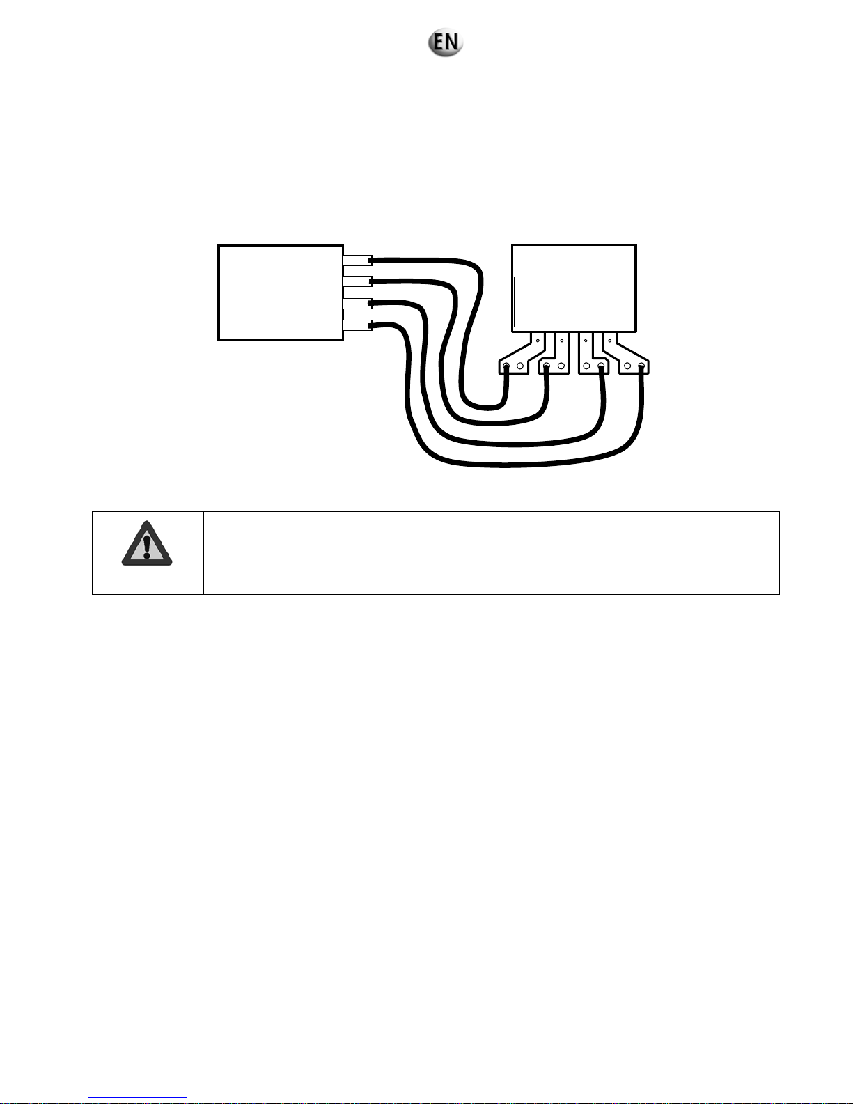
6.3.5.6. Power
1. Pass the power cables through the access hatch to the power box of the generating set (AIPR or console, depending on the
generating set).
2. Connect the power cables to the busbars.
3. Connect the power cables to the application.
Check that the direction of rotation of the phases between the generating set and the application is the
same.
Important
Type of cables: Use H074NF type cables according to the standards in force in the country of use of the generating set (In
France refer to the standard C15.100).
6.3.5.7. Client terminal block
Refer to the wiring diagrams according to the configuration selected and the requirements.
GENERATING SET
APPLICATION
N R
S T
85/285
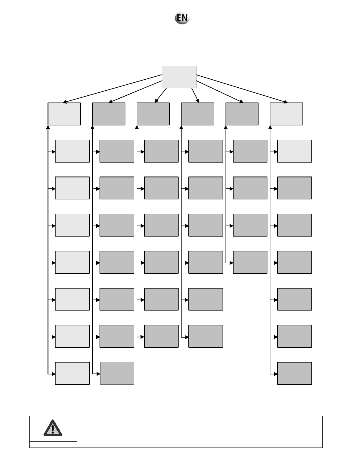
6.3.6 Operation and setting menus
6.3.6.1. Layout of the menus
The diagram below shows the layout of the main menus.
-1 -
Operation
-2 -
Fault finding
-3 -
Archiving
& Metering
-4 -
Maintenance
-5 -
Configurations
-6 -
System
-0 -
Home
-1.2 -
Function keys
-1.3 -
Synchro.
Column
-1.4 -
Power plant
measurements
synthesis
-1.5 -
Measurements
-1.6 -
Alarms
& faults
-1.7 -
User settings
- 2.1 -
Digital
Variables
- 2.2 -
Analog variables
- 2.3 -
REG & PRO
variables
- 2.4 -
Curves
- 3.1 -
Events
archives
- 3.2 -
Electrical
archives
- 3.3 -
Mechanical
archives
- 3.4 -
Events
metering
- 3.5 -
Mechanical
metering
- 3.6 -
Electrical
metering
-1.1 -
Operation
-4.1 -
Provider
-4.2 -
Emails
-4.3 -
Service
intervals
-4.4 -
Consumables
-4.5 -
Progress reports
- 5.1 -
Equipment
- 5.2 -
Applications
- 5.3 -
Regulations
- 5.4 -
Safety features
- 6.1 -
Regional
parameters
- 6.2 -
Application
identification
- 6.3 -
Software
versions
- 6.4 -
Printing
- 6.5 -
Access
management
- 6.6 -
Web access
management
- 6.7 -
Factory
- 2.5 -
Electrical
faults
- 2.6 Help
-4.6 -
Reports
-2.7 -
Regulation mode
display
Only the menu functions on a white background are described in this manual.
Important
86/285

6.3.6.2. Setting of regional parameters
Without an input access code this screen allows:
input of the display language
setting of date and time
Navigation reference: 6.1
15/07/09 19 :10 :00 GS 1 Regional parameters Stop Faults Alarms
Français English Espanol Deutsch Portugues
Language
option
Day Month Year hours Minutes Seconds
22 10 07 17 10 00
Inhibit the keys
- 1 –
Identification
application
- 2 -
Software versions
- 3 -
Printing
To clean the touch screen (dust, hydrocarbons, etc.) the key inhibition function prevents keys on the screen from being
pressed for some twenty seconds. A special screen shows the time elapsing.
87/285
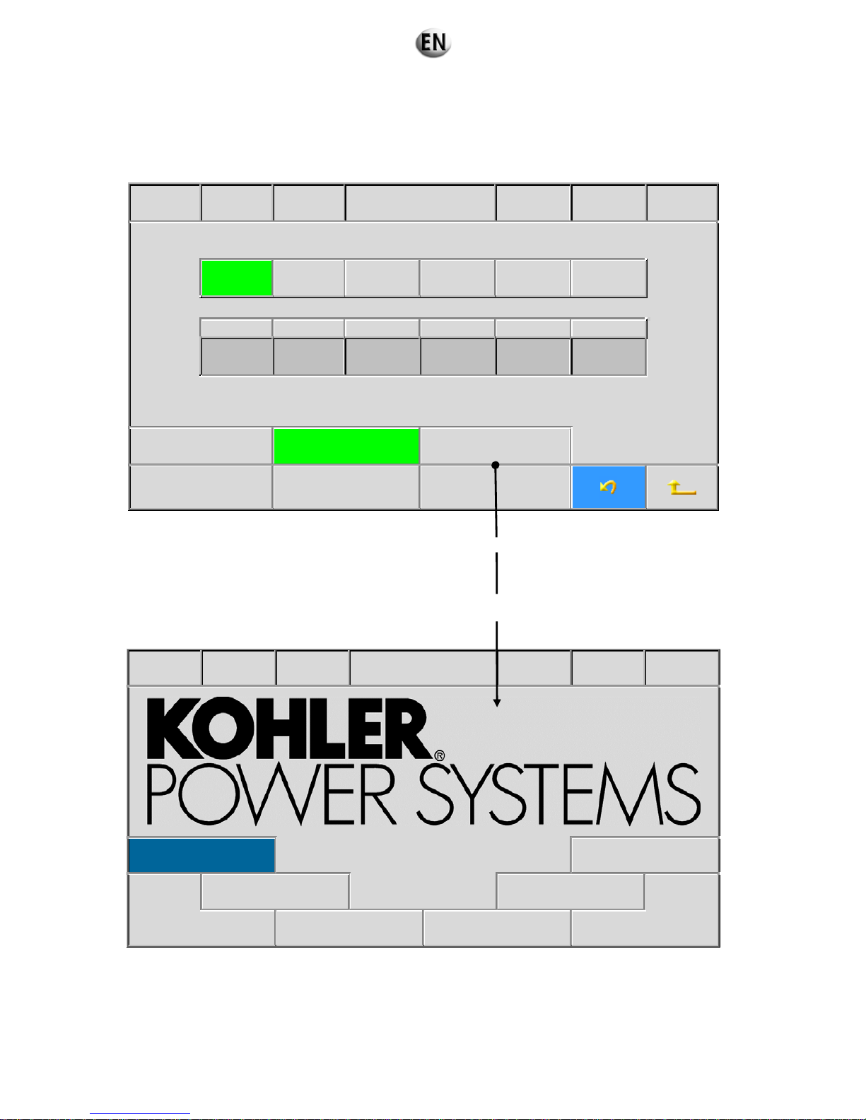
When an access code of a sufficient level is validated this screen also allows:
Setting of the module synchronisation time
Selection of the logo displayed on the Kerys home screen.
When the time setting by the SNTP protocol is not active the screen looks like this.
15/07/09 19 :10 :00 GS 1 Regional parameters Stop Faults Alarms
Français English Espanol Deutsch Portugues
Language
option
Day Month Year hours Minutes Seconds
22 10 07 17 10 00
Inhibit the keys SDMO welcome logo KOHLER welcome logo
- 1 -
Identification
application
- 2 -
Software versions
- 3 -
Printing
In this case the transmission of a signal to the bus, enabling the different real time clocks to be reset, is defined by the
synchronisation time.
Pressing the “KOHLER home logo” key alters the appearance of the home screen by replacing the KOHLER logo with the SDMO
logo as default. The home screen then looks like this:
15/07/09 19 :10 :00 GS 1 Welcome Auto Faults Alarms
- 1 -
Operation
- 6 -
System
- 2 -
Fault finding
- 5 -
Configuration
- 3 -
Archiving/Metering
-4 -
Maintenance
88/285

In the second case the screen has this appearance.
15/07/09 19 :10 :00 GS 1 Regional parameters Stop Faults Alarms
Français English Espanol Deutsch Portugues
Language
option
Day Month Year hours Minutes Seconds
22 10 07 17 10 00
Inhibit the keys SDMO welcome logo KOHLER welcome logo
- 1 -
Identification
application
- 2 -
Software versions
- 3 -
Printing
6.3.6.3. Information on the KERYS
Indication of the application
Navigation reference
: 6.2
This screen enables SDMO to identify the project.
This information is required for queries sent to SDMO’s customer service, so that the associated file can b e consu l ted .
15/07/09 19 :10 :00 GS 1
Identification
application
Stop Faults Alarms
Site name
Dealership number 000000
OM number 000000
Connection number 000000
- 1 -
Software versions
- 2 -
Printing
- 3 -
Access management
Project number: reference of the production file for the control equipment.
OM number: reference of the production file for the generating set.
Connection number: reference used to identify the site at the time of the telephone connection.
89/285

Software version
Navigation reference: 6.3
The information relating to the software versions installed in the different modules is accessible from this menu. Only the lines
corresponding to the installed equipment appear
15/07/09 19 :10 :00 GS 1 Software versions Stop Faults Alarms
Module Software versions Softw are version dates
IHM 0.00 00/00/00
Base 0.00 00/00/00
Resident logic 0.00 00/00/00
Regulation 0.00
Protection 0.00
Engine 0.00
- 1 -
Identification
application
- 2 -
Printing
- 3 -
Access management
90/285
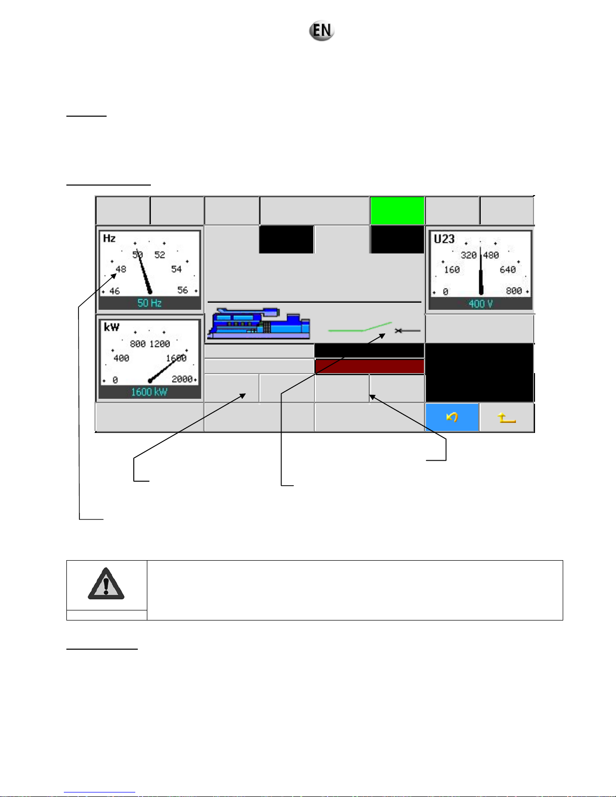
6.3.6.4. Operating menus
Operation
This main screen displays all the main electrical parameters of the generating set.
It is the general operating and monitoring screen for the generating set.
This screen can also be displayed by pressing the indicator displaying the operation mode of the generating set.
The frequency, U23 voltage, active and reactive power indicators, can be displayed in analog or digital form. Switching from one
mode to another is performed by pressing the desired indicator.
Navigation reference: 1.1
15/07/09 19:10 :00 GS 1 Operation Manu Faults Alarms
I1 (A) 2701 P.F. 0,9 L
Status messages
Q (kVAr)
Speed (rpm) 1505
765
Operating time: 10 :05
+ F - F + U -U
- 1 -
Function keys
- 2 -
Synchro. column
- 3 -
Central unit measure.
summary
In the needle dials the nominal values are in blue
The speed and voltage adjustment keys are only displayed for coupled applications in manual mode.
Important
Alarms and faults
This menu can also be called directly by pressing the flashing “Alarms” and “Faults” keys on the upper band.
This screen allows the user to view the list of faults present on the installation.
The first two columns give details of the date and time that the fault appeared.
The
“Status” column indicates whether the fault is still present “1”, or not present “0”.
The “
@” column gives the address of the variable associated with the fault.
The
“Text” column identifies the type of fault.
A line with a red background characterises a fault and a line with an orange background characterises an alarm.
The dial is automatically scaled beyond 46Hz
Indication de la position du départ groupe
Commande de la vitesse de
rotation du moteur
Commande de la tension de
l’alternateu
r
Indication of the genset output position
Control of speed of rotation of
the engine
Control of alternator voltage
91/285

Navigation reference: 1.6
15/07/09 19 :10 :00 GS 1 Alarms & Faults Stop Faults Alarms
Date Time Status @ Title
26/11/03 11:11:12’55 1 6131 HT LOW COOLANT LEVEL FAULT
26/11/03 10:35:16’28 0 6017 INSULATION 1 ALARM
26/11/03 10:10:10’10 0 60C3
CIRCUIT BREAKER FAULT ON GENERATING SET
OUTPUT
-1-
Function keys
-2-
Synchro. column
-3-
Central unit measure.
summary
To clear a fault, it is necessary to:
check that the fault has disappeared (status 0) and whether it is necessary to eliminate its causes
select the line in question; the text on the line is displayed in white
press the “Reset” key on the keypad; the line is deleted.
When a fault is displayed, its effect on the operation remains active even if its cause has disappeared.
When in Manu or Auto mode, if the user wants to clear a fault with a "stopped" clearance mode, a screen
will inform the user to switch to stop mode.
Important
Keys for scrolling when the list is longer than the number
of lines possible on the screen, i.e. 4 lines
Active line
92/285

6.3.7 Rental configurations
6.3.7.1. Choice of application configuration
Solo generating set Without inverter (A612)
1. Turn off the battery isolator switch.
2. Check that the emergency stop buttons are activated.
3. Press the “STOP” button on the KERYS.
4. Turn the changeover switch to position 1.
1: SOLO GENERATING SET WITHOUT GRID COUPLING
APPLICATION:
A612
2: PRODUCTION POWER PLANT WITHOUT GRID COUPLING
APPLICATION:
A632 / A633
3: NOT APPLICABLE
4 : SOLO GENERATING SET WITH GRID COUPLING
APPLICATION:
A651
(If the switch is already set to “
1”, turn the switch and return to position ‘’1’’)
After changeover, the screen below appears.
15/07/09 19:10 :00 GS 1 Rental application Stop Faults Alarms
A612: Single Genset without N/E
Validation
Mains supply detection using the adjustment card
Mains supply detection using an external contact
1
4
3
2
93/285
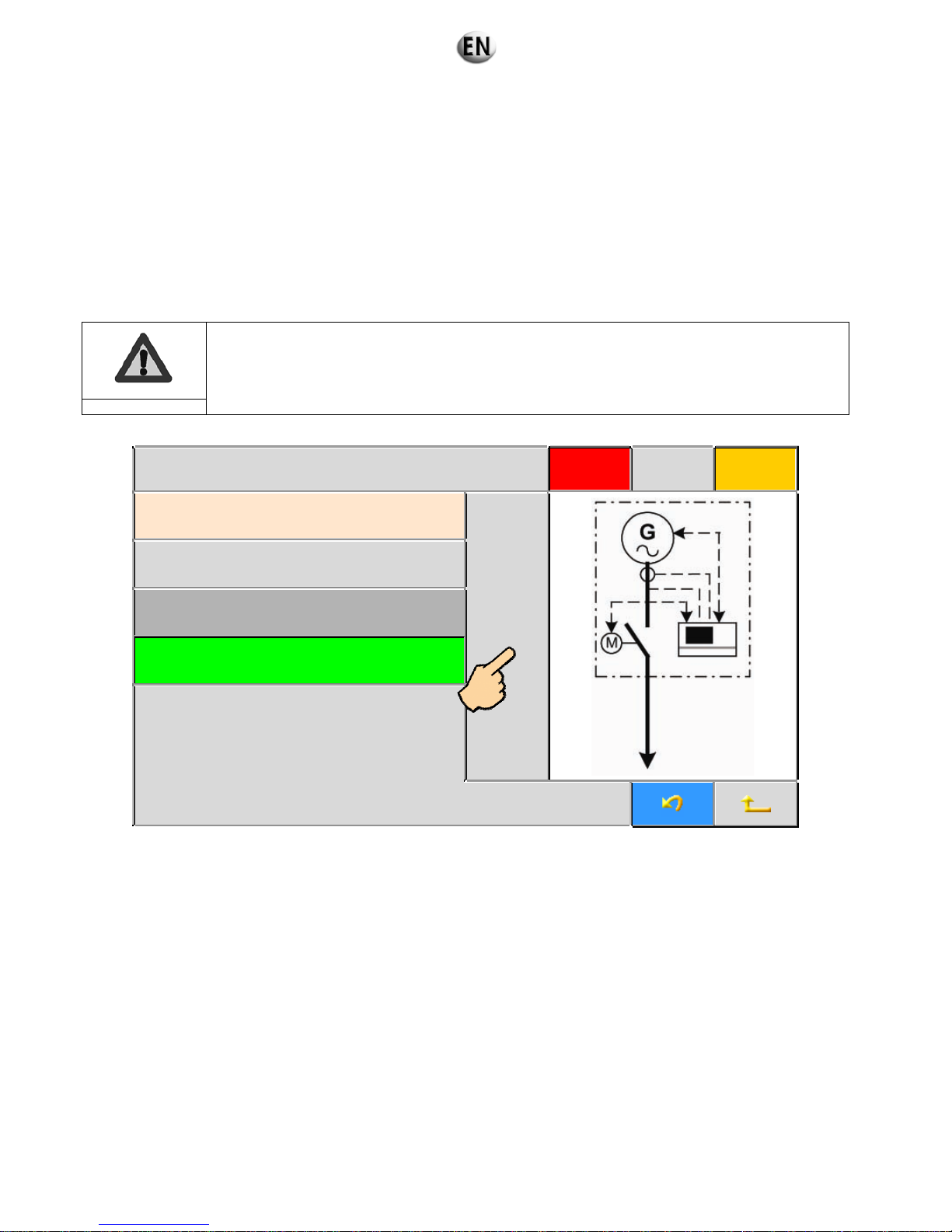
5. Select the configuration of the mains detection of the generating set by clicking directly on the touch screen.
For a mains detection by means of the regulation card you must select the configuration “Mains supply detection
using the adjustment card”
and connect the voltage reference to the terminals Xcbc1 - 1-2-3.
For mains detection by an external switch you must select the configuration “Mains supply detection using an external
contact”
and connect the external switch to the terminals Xcbc3 - 34-35.
For starting by means of an external switch you must select the configuration “Mains supply detection using an
external contact”
and connect the external switch to the terminals Xcbc3 - 32-33.
For solo starting, in the absence of a mains connection, you must select the configuration “Mains supply detection using
an external contact”
. No connection is necessary.
N.B. selecting detection depends on the connection made according to Section “Connections of the
generating sets”.
Important
15/07/09 19:10 :00 GS 1 Rental application Stop Faults Alarms
A612: Single Genset without N/E
Validation
Mains supply detection using the adjustment card
Mains supply detection using an external contact
6. Press “Validation" on the touch screen.
94/285

Back-up to perform GS 1 Rental application Stop Faults Alarms
A612: Single Genset without N/E
Validation
Mains supply detection using the adjustment card
Mains supply detection using an external contact
7. The KERYS saves your new configuration.
8. After return to the KERYS home screen,
The configuration will only be taken into account if the following operations are carried out:
Turn on the battery isolator switch.
Wait 5 seconds.
Turn off the battery isolator switch.
Important
Solo generating set, CRF coupling (A651)
1. Turn off the battery isolator switch.
2. Check that the emergency stop buttons are activated.
3. Press the “STOP” button of the KERYS.
4. Turn the changeover switch to position 4.
1: SOLO GENERATING SET WITHOUT GRID COUPLING
APPLICATION:
A612
2: PRODUCTION POWER PLANT WITHOUT GRID COUPLING
APPLICATION:
A632 / A633
3: NOT APPLICABLE
4 : SOLO GENERATING SET WITH GRID COUPLING
APPLICATION:
A651
(If the switch is already set to “
4”, turn the switch and return to position ‘’4’’)
Saving in flash …
1
4
3
2
95/285

After changeover, the screen below appears.
15/07/09 19:10 :00 GS 1 Rental application Stop Faults Alarms
A651: Temporary power grid single Genset
coupling
Validation
Grid CT ratio 20.0
5. To enter the value of the grid current transformer ratio: press the
“GRID CT RATIO” button on the touch screen.
Using the alphanumeric keys of the MICS KERYS: enter the value of the CT ratio in tenths.
Example: CT = 100A/5A (calculation: 100/5 =
20; 20x10=200) value to be entered 200.
CT BUSBAR/Grid setting 1 (1/10)
0<= 0200 <=32767
Valid Esc.
6. Then press “
VALID” .
96/285

15/07/09 19:10 :00 GS 1 Rental application Stop Faults Alarms
A651: Temporary power grid single Genset
coupling
Validation
Grid CT ratio 20.0
7. Press the “Validation” button on the touch screen.
15/07/09 19:10 :00 GS 1 Rental application Stop Faults Alarms
A651: Temporary power grid single Genset
coupling
Validation
Grid CT ratio 20.0
8. The KERYS saves your new configuration.
Saving in flash …
97/285
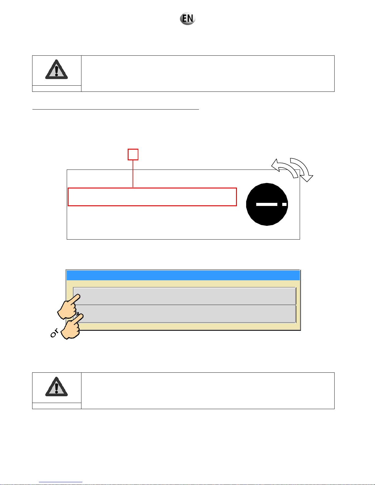
9. After return to the KERYS home screen,
The configuration will only be taken into account if the following operations are carried out:
Turn on the battery isolator switch.
Wait 5 seconds.
Turn off the battery isolator switch.
Important
Power plant Without common part and without inverter (A632-A 633)
1. Turn off the battery isolator switch.
2. Check that the emergency stop buttons are activated.
3. Press the “STOP” button on the KERYS.
4. Turn the changeover switch to position 2.
1: SOLO GENERATING SET WITHOUT GRID COUPLING
APPLICATION:
A612
2: PRODUCTION POWER PLANT WITHOUT GRID COUPLING
APPLICATION:
A632 / A633
3: NOT APPLICABLE
4 : SOLO GENERATING SET WITH GRID COUPLING
APPLICATION:
A651
(If the switch is already set to “
2”, turn the switch and return to position ‘’2’’)
After changeover, the screen below appears.
Choix configuration centrale loueur
A632: Power plant without shared switching unit without Normal/Emergency parallel line
A633: Power plant without shared switching unit without Normal/Emergency Digital Bus
5. Select the configuration “
A632: Power plant without shared switching unit without Normal/Emergency parallel line” by
directly clicking on the touch screen.
Select the configuration “
A633: Power plant without shared switching unit with out Normal/Emergency Digital Bus” by
clicking directly on the touch screen.
N.B. selecting detection depends on the connection made according to Section 5. “Connections of
the generating sets”.
Important
1
4
3
2
98/285
 Loading...