


33
C
3
User and maintenance manual
for generating sets
33504023701NE_2_1
Translation of the original instructions
R


1/242
CONTENTS
1. Preface .................................................................................................................................................................................................. 4
1.1. General recommendations ....................................................................................................................................................... 4
1.2. Warnings .................................................................................................................................................................................. 4
1.3. Pictograms and their meanings ................................................................................................................................................ 5
1.4. Safety instructions .................................................................................................................................................................... 8
1.4.1 General guidelines .................................................................................................................................................................... 8
1.4.2 Electrical safety precautions ................................................................................................................................................... 10
1.4.3 Safety precautions in case of electrical shock ........................................................................................................................ 11
1.4.4 Safety precautions relating to fire, burns and explosions ....................................................................................................... 11
1.4.5 Toxic risk safety precautions .................................................................................................................................................. 13
1.4.6 Precautions for risks relating to handling phases ................................................................................................................... 14
1.4.7 Precautions for risks relating to noise ..................................................................................................................................... 14
2. General description .............................................................................................................................................................................. 15
2.1. Description ............................................................................................................................................................................. 15
2.2. Technical specifications ......................................................................................................................................................... 18
2.3. Identifying sets ....................................................................................................................................................................... 20
2.4. Fluid retention ........................................................................................................................................................................ 21
2.5. Fuels, lubricants and coolants ................................................................................................................................................ 22
2.5.1 Fuel specifications .................................................................................................................................................................. 22
2.5.2 Lubricant specifications .......................................................................................................................................................... 24
2.5.3 Coolant specifications ............................................................................................................................................................. 25
3. Transporting the equipment ................................................................................................................................................................. 27
3.1. Warnings concerning transport .............................................................................................................................................. 27
3.2. Preparing for transport ........................................................................................................................................................... 27
3.3. Road transport ....................................................................................................................................................................... 27
3.3.1 Generating sets with and without an enclosure ...................................................................................................................... 27
3.3.2 Generating sets on trailers...................................................................................................................................................... 28
3.3.2.1. Hitching and unhitching the trailer ............................................................................................................................. 28
3.3.2.2. Check before towing ................................................................................................................................................. 32
3.3.2.3. Operation .................................................................................................................................................................. 32
3.4. Rail transport .......................................................................................................................................................................... 33
3.4.1 Generating sets with and without an enclosure ...................................................................................................................... 33
3.5. Shipping ................................................................................................................................................................................. 34
3.5.1 Generating sets with and without an enclosure ...................................................................................................................... 34
3.6. Air transport ........................................................................................................................................................................... 34
4. Installation - Connections .................................................................................................................................................................... 35
4.1. Unloading the generating set ................................................................................................................................................. 35
4.1.1 Choosing the location ............................................................................................................................................................. 35
4.1.2 Safety during unloading .......................................................................................................................................................... 36
4.1.3 Unloading the generating set .................................................................................................................................................. 36
4.1.3.1. Slings ........................................................................................................................................................................ 36
4.1.3.2. Fork lift truck ............................................................................................................................................................. 37
4.1.4 Moving the generating set ...................................................................................................................................................... 37
4.2. Connecting the generating set ............................................................................................................................................... 38
4.2.1 Connection summary .............................................................................................................................................................. 38
4.2.2 Protecting people and equipment ........................................................................................................................................... 39
4.2.2.1. Earthing system principle .......................................................................................................................................... 39
4.2.2.2. TT system ................................................................................................................................................................. 39
4.2.2.3. Installing the differential protection ........................................................................................................................... 40
4.2.2.4. Setting the generating set differential protection ....................................................................................................... 41
4.2.2.5. Earthing the generating set ....................................................................................................................................... 43
4.2.3 Making the connections .......................................................................................................................................................... 44
4.2.3.1. Connections - general information ............................................................................................................................ 44
4.2.3.2. Selecting the power cables ....................................................................................................................................... 45
4.2.3.3. Connecting the generating set to the installation ...................................................................................................... 46
4.2.3.4. Connecting the battery or batteries to the generating set ......................................................................................... 48
4.2.4 Overvoltage ............................................................................................................................................................................ 48
5. Installation............................................................................................................................................................................................ 48
5.1. Warnings concerning commissioning ..................................................................................................................................... 48
5.2. Checking the generating set installation ................................................................................................................................ 48
5.3. Preparing for operation of the generating set ......................................................................................................................... 49
5.4. Checking the generating set before startup ........................................................................................................................... 49
5.5. Checking the generating set after startup .............................................................................................................................. 49

2/242
6. Using the generator set ....................................................................................................................................................................... 50
6.1. Pre-Start Inspection ............................................................................................................................................................... 50
6.2. Generator set with NEXYS control panel ............................................................................................................................... 53
6.2.1 Control panel presentation ..................................................................................................................................................... 53
6.2.1.1. Introduction to pictograms ......................................................................................................................................... 54
6.2.2 Manual starting ....................................................................................................................................................................... 55
6.2.3 Switching off ........................................................................................................................................................................... 56
6.2.4 Alarms and faults .................................................................................................................................................................... 56
6.2.5 Faults and alarms - Details ..................................................................................................................................................... 56
6.2.6 MURPHY diagnostic module .................................................................................................................................................. 58
6.3. Generator set with TELYS control panel ................................................................................................................................ 64
6.3.1 Control panel presentation ..................................................................................................................................................... 64
6.3.1.1. View of the front panel .............................................................................................................................................. 64
6.3.1.2. Description of the screen .......................................................................................................................................... 66
6.3.1.3. Description of the pictograms in zone 1 .................................................................................................................... 67
6.3.1.4. Description of the pictograms in zone 2 .................................................................................................................... 68
6.3.1.5. Description of the pictograms in zone 3 .................................................................................................................... 69
6.3.1.6. Display of messages in zone 4 ................................................................................................................................. 71
6.3.2 Starting ................................................................................................................................................................................... 76
6.3.3 Switching off ........................................................................................................................................................................... 77
6.3.4 Alarms and faults .................................................................................................................................................................... 77
6.3.4.1. Viewing alarms and faults ......................................................................................................................................... 77
6.3.4.2. Activation of an alarm or fault ................................................................................................................................... 78
6.3.4.3. Activation of an alarm and a fault .............................................................................................................................. 79
6.3.4.4. Engine fault codes display ........................................................................................................................................ 80
6.3.4.5. Horn reset ................................................................................................................................................................. 81
7. Maintenance schedule ......................................................................................................................................................................... 81
7.1. Reminder of use ..................................................................................................................................................................... 81
7.2. Maintenance safety instructions ............................................................................................................................................. 81
7.3. Table of maintenance operations ........................................................................................................................................... 82
7.4. Cover maintenance ................................................................................................................................................................ 83
7.5. Trailer maintenance ............................................................................................................................................................... 83
7.6. Fault finding ........................................................................................................................................................................... 84
7.7. No load and under load tests ................................................................................................................................................. 84
8. Starter batteries ................................................................................................................................................................................... 85
8.1. Checking the electrolyte level ................................................................................................................................................ 85
8.2. Checking the voltage/acid density .......................................................................................................................................... 85
8.3. Charging the battery .............................................................................................................................................................. 86
8.4. Cleaning the battery ............................................................................................................................................................... 86
8.5. Fault finding ........................................................................................................................................................................... 87
9. Options ................................................................................................................................................................................................ 88
9.1. Dual frequency ....................................................................................................................................................................... 88
9.2. Neutral system ....................................................................................................................................................................... 91
9.3. Fuel supply valve ................................................................................................................................................................... 91
10. Appendix ............................................................................................................................................................................................ 93
10.1. Appendix A – Engine user and maintenance manual ............................................................................................................ 93
10.2. Appendix B - Alternator user and maintenance manual ........................................................................................................191

3/242
TABLE OF ILLUSTRATIONS
Figure 1 : Warning pictograms .................................................................................................................................................................. 5
Figure 2 : Pictograms indicating prohibited activities ................................................................................................................................. 5
Figure 3 : Pictograms indicating compulsory operations ........................................................................................................................... 6
Figure 4 : Information pictograms .............................................................................................................................................................. 6
Figure 5 : Specific pictograms ................................................................................................................................................................... 7
Figure 6 : Pictograms relating to battery operations .................................................................................................................................. 7
Figure 7 : General description of the generating set ................................................................................................................................ 15
Figure 8 : General description of the generating set (Continuation) ........................................................................................................ 16
Figure 9 : General description of the generating set (control) .................................................................................................................. 17
Figure 10 : Example of a generating set identification plate .................................................................................................................... 20
Figure 11 : Fluid retention container ........................................................................................................................................................ 21
Figure 12 : Example of French signalling ................................................................................................................................................ 33
Figure 13 : Examples of problems that may be encountered .................................................................................................................. 35
Figure 14 : Points used for lifting and moving .......................................................................................................................................... 37
Figure 15 : TT earthing system ................................................................................................................................................................ 39
Figure 16 : View of the front side ............................................................................................................................................................. 53
Figure 17 : Description of the LEDs ......................................................................................................................................................... 54
Figure 18 : View of pictograms ................................................................................................................................................................ 54
Figure 19 : View of the front panel ........................................................................................................................................................... 64
Figure 20 : Description of the LEDs ......................................................................................................................................................... 65
Figure 21 : Close-up of USB ports ........................................................................................................................................................... 65
Figure 22 : Description of the screen (example) ...................................................................................................................................... 66
Figure 23 : Trailer lubrication/greasing points .......................................................................................................................................... 83

4/242
1. Preface
1.1. General recommendations
The information contained in this manual is taken from technical data available at the time of print. In line with our policy of continually
improving the quality of our products, this information may be amended without warning.
Read the safety instructions attentively in order to prevent any accident, incident or damage. These instructions must be adhered to
constantly.
In order to obtain optimum efficiency and the longest possible service life for the generating sets, maintenance operations must be
carried out according to the periods indicated in the attached maintenance tables. If the generating set is used under dusty or
unfavourable conditions, some of these periods will be shorter.
Ensure that all adjustments and repairs are carried out by personnel who have received appropriate training. Our agents possess this
qualification, and can answer all of your questions. They can also supply you with spare parts and other services and they have
qualified staff to carry out preventive and corrective maintenance or even total reconditioning of generating sets.
The left and right sides can be seen from the back of the generating set (the radiator is at the front).
: some user and maintenance manuals for engines fitted to gener ating sets cover control units and include the start-up and sh ut
Note
down procedures for the engines.
As our generating sets are fitted with control units that are specific to the generating sets; only the i nformation that appears in the
documentation for the generating set control units should be taken into consideration.
In addition, depending on the manufacturing criteria of the generating sets, some engines may be fitted with specific electrical wiring
different to that described in the engine documentation.
1.2. Warnings
In this manual, the warning messages are used as follows:
Immediate danger.
Indicates an imminent danger which may result in death or serious injury. Failure to follow the instruction
shown may pose serious risks to the health and life of those concerned.
DANGER
Potential danger.
IMPORTANT
Indicates a dangerous situation if the warning is not heeded. Failure to follow the instruction indicated may
cause minor injuries to those concerned or damage to equipment.

5/242
1.3. Pictograms and their meanings
The aim of the pictograms is as follows:
- To draw the attention of the operator or maintenance technician to the potential dangers.
- To explain how to act in the interest of personal safety and to avoid damaging the equipment.
The safety pictograms present on the equipment are explained below.
Warning: danger
Important,
toxic materials
Important,
high temperature
Important,
Electrical risk
Important,
rotating or moving
parts
Important,
corrosive product
Important,
risk of explosion
Important,
pressurised fluids
Danger: automatic
start-up
Figure 1 : Warning pictograms
Entry prohibited to
unauthorised
persons
Figure 2 : Pictograms indicating prohibited activities
Jet washing
prohibited

6/242
Reading the
manual for the
equipment is
compulsory
Lifting point
required
Periodic
maintenance
compulsory
Figure 3 : Pictograms indicating compulsory operations
Earth
Wearing suitable
protective clothing
is compulsory
Forklift required for
lifting
Battery isolating
switch
Wearing suitable
protective goggles
and ear defenders
is compulsory
Battery charge
must be checked
External fuel
connections
Diesel fuel
Fill the coolant
Fill the oil
Retention container
high level
Drain the fuel
Drain the coolant
Drain the oil
Drain the retention
container
Figure 4 : Information pictograms
Inspection flap
Mains supply
connection
prohibited before
filling with water

7/242
Flammable product,
Do not smoke or create sparks or flames
Fuel supply
- Selection valve -
Figure 5 : Specific pictograms
Reading the manual for the equipment is
compulsory
Securing straps routing point
Rinse any splashes of acid on the skin or
in the eyes using clean water.
Wearing suitable protective clothing and
goggles is compulsory
Consult a doctor immediately.
Wash contaminated clothing with water.
Figure 6 : Pictograms relating to battery operations

8/242
1.4. Safety instructions
RETAIN THIS MANUAL
This manual contains important instructions which must be followed when installing or carrying out maintenance on a generating set
and batteries.
IMPORTANT - SAFETY ADVICE
If any parts of this manual are not understood, or in case of doubt, contact your nearest agent in order to receive an explanation or
demonstration to allow the equipment to be used correctly. The guidelines listed below must always be respected to ensure the safety
of personnel and equipment. In addition to this information, it is essential to refer to the local and national regulations applicable
according to the jurisdiction.
1.4.1 General guidelines
Installing the equipment
The installer of the equipment must create a document describing any modifications made to the equipment during installation.
Using the equipment
- Before starting any operations on the equipment:
Nominate an operations manager.
The role of the operations manager is to monitor, either directly or indirectly, any operations performed on the equipment
and to ensure that the safety and operating instructions are respected.
The operations manager should read and understand all the documentation supplied with the equipment.
- Information for personnel:
Regularly reiterate the safety and operating instructions to the operating personnel.
Contact your dealer if you have any questions regarding the equipment and any training requests for personnel.
Make the manufacturer's instructions available to the users (if possible on site).
- Protection for individuals and equipment:
Wear suitable clothing.
Move away from equipment in operation.
Ensure that persons who are not authorised to intervene as well as animals are kept away from the equipment. Observe
this guideline regardless of whether the equipment is in operation or stopped.
Protect the equipment from any fluid splashes and bad weather.
Before starting the equipment, refit the enclosures and close all the access doors.
Before starting the engine, check that the air filter is present and the correct extraction circuit for the exhaust gas.
Respect the current regulations relating to fuel use.
Under no circumstances use seawater or any other corrosive or electrolytic product in the cooling circuit.
Adjust the equipment according to the manufacturer's prescriptions.
Check that the equipment operates correctly.
Engage the parking brake when the equipment is installed on the operating site on its trailer. When chocking the trailer on
a slope, ensure that there is nobody in the path of the trailer.

9/242
Maintaining the equipment
- Personnel skills:
Ensure that the maintenance operations are performed on the equipment by appropriately trained personnel.
- Personnel protection:
Wear suitable clothing and protective goggles.
Remove any personal belongings that may hinder the operation: watch, bracelet, etc.
Fit a panel over the controls of the equipment to prevent any attempt to start.
Disconnect the battery (and pneumatic starter if fitted) before beginning any maintenance operation.
Handle the equipment according to best practices, using techniques which do not endanger the personnel.
It is essential to wear gloves when detecting leaks.
Regularly check that the safety devices are operating correctly.
- Equipment protection:
Use tools in good condition and suited to the work to be done. Ensure you have understood the instructions before
beginning any operation.
Respect the maintenance table and its recommendations. In dusty or unfavourable conditions, certain maintenance
intervals will need to be reduced.
Check that the spare parts fitted on the equipment are supplied only by the dealer.
Handle the equipment according to best practices, using techniques which do not risk damaging the equipment.
Replace any safety pictograms that are missing or illegible on the equipment.
Note
: the mounting bolts on the protective devices of t he rotating parts are captive bolts equipped with retaining washers.
Also, in order to ensure the integrity of this assembly, it is prohibited to use elec tric or pneumatic screwdrivers to undo these
mounting bolts.
- Cleaning the equipment:
Clean off any trace of oil, fuel or coolant using a clean cloth.
Use only approved cleaning solvents.
Cleaning products and methods that are strictly prohibited:
• petrol or other flammable substances;
• soapy solution containing chlorine or ammonia;
• high pressure cleaner.
- Additional instruction:
If necessary, contact the dealer for the following reasons:
• answers to any questions relating to the equipment;
• training requests for personnel;
• supplying the relevant documentation for maintenance operations;
• supplying spare parts;
• corrective or preventive maintenance operations.

10/242
Operating site
- Maintenance:
Clean the entire operating site regularly with suitable cleaning materials.
The presence of dangerous or combustible materials inside premises must be limited to the operating requirements.
- Access:
Prohibit free access to persons who are not part of the establishment, except for those designated by the user.
- Respecting the environment:
Drain and dispose of engine oil in a specially provided container (fuel distributors can collect your used oil).
Burning of waste in the open air is prohibited.
Remove waste water, sludge and other waste in a specialised processing centre.
1.4.2 Electrical safety precautions
DANGER
- Read the manufacturer's identification plate carefully. The values for voltage, power, current and frequency are shown. Check
that these values match the installation being supplied.
- The electrical connections must be made in accordance with current standards and regulations in the country of use and the
neutral system sold.
- Ask a qualified electrician to intervene when there are specific cases requiring equipment to be connected to an existing
electrical network.
- Disconnect the power to the equipment (equipment voltage, battery voltage and network voltage) before any installation or
maintenance operation is performed.
- Connect the equipment wires by respecting the wiring diagram supplied by the manufacturer.
- Always handle the equipment with dry hands and feet.
- Take all the necessary precautions to avoid touching stripped cables or disconnected connectors.
- Use and maintain the cables in good condition, well insulated and connected correctly and securely.
- Only replace equipment that provides protection against electric shock with identical equipment (specifications and nominal
values).
- Only use flexible durable cables with a rubber covering, which conform to ECI 245-4, or equivalent cables.
- Refit the protective plates (blanking covers) after each maintenance operation.
ELECTRICAL EQUIPMENT - RISK OF ELECTRIC SHOCKS
Note
: The electrical equipment supplied with the equipment co mplies with standard NF C15.100 (F rance), or with the standards of th e
countries in question.

11/242
1.4.3 Safety precautions in case of electrical shock
In the event of an electric shock, observe the following instructions:
1. Avoid direct contact both with the live conductor and the victim's body.
2. Shut off the power immediately and activate the emergency stop for the
equipment concerned. Note
care to avoid the electric arc that will be generated by this.
3. If it is impossible to access the equipment: move the victim away from the live
conductor using a dry piece of wood, dry clothing or other non-conducting
material.
4. Move the victim away from any situations where there is a danger of death.
5. Contact the emergency services.
6. If breathing has stopped, begin artificial respiration at once.
7. In the event of cardiac arrest, carry out cardiac massage.
1.4.4 Safety precautions relating to fire, burns and explosions
: the live wire may be cut with an axe. Take extreme
DANGER
FUELS / FLAMMABLE PRODUCTS / PRESSURISED FLUID
- RISK OF BURNS -
- RISK OF FIRE -
- RISK OF EXPLOSION -
1. Before starting the equipment, move any flammable or explosive products away (petrol, oil, cloth, etc.).
2. It is prohibited to put combustible materials on the hot parts of the equipment (for example: exhaust pipe).
3. Avoid any contact with the hot parts of the equipment (for example: exhaust pipe).
4. Use appropriate ventilation to allow the equipment to cool correctly.
5. Wait for the engine to stop and cool down completely before removing the radiator cap.
6. Wait for the equipment to stop and cool down completely before covering the equipment (if necessary).
7. Depressurise the air, oil and cooling circuits before removing or disconnecting all the fittings, pipes or connected components.
8. Ensure that the equipment in operation is fixed (in a stationary position).
When installing the equipment on a vehicle or other mobile equipment, a study must be conducted
beforehand in order to take into account the various specific uses of the generating set.
IMPORTANT

12/242
Fuels
- Respect current local regulations regarding the equipment and fuel used
(petrol, diesel and gas).
- Top up the engine with fuel when the engine has stopped (except for
equipment with an automatic filling system).
- Smoking, using a flame or producing sparks are forbidden while the fuel
tank is being filled.
- Use protection suitable against fires and explosions.
- Pipes must be replaced as soon as their condition demands it.
Oils
1. Check that the system is no longer pressurised before carrying out any procedures.
2. Avoid contact with hot oil.
3. Wait for the engine to stop and cool down completely before topping up the oil.
4. Before starting the engine, refit the oil filler cap.
5. It is prohibited to cover the generating set with a fine layer of oil for anti-rust protection.
Battery
- Smoking, using a flame or producing sparks are forbidden close to batteries (particularly when the batteries are being
charged).
Supply gas
(concerns generating sets running on gas)
- Request the user technical notes and LPG or NG safety data sheets from your gas supplier.
- For any operation on a gas installation, ask a recognised specialist to intervene.
- Gas supply procedures must be carried out in the open air (outside) in accordance with local regulations, in an area well away
from fires, people or animals.
- Check the sealing of the gas supply circuit using soapy water with the circuit pressurised, or using a leak detector.
- It is forbidden to smoke, bring flames near or create sparks when the tank is being filled, and near to the generating set.

13/242
1.4.5 Toxic risk safety precautions
DANGER
EXHAUST GAS - TOXIC PRODUCTS
- TOXIC RISK -
Exhaust gas
- Use suitable ventilation to release the exhaust gas outside and prevent it from
accumulating.
- Respect current local regulations regarding the equipment and fuel used (petrol, diesel
and gas).
- Periodically examine the burnt gas exhaust.
- Pipes must be replaced as soon as their condition demands it.
Note
: the carbon monoxide present in the exhaust gas may lead to death by inhalation if the concentration l evels i n the atmosphere are
too high.
Corrosion inhibitor in the coolant
(contains alkali)
- Read the instructions on the packaging.
- Keep the product out of the reach of children.
- Do not swallow it.
- Avoid prolonged or repeated contact with the skin.
- Never allow contact with the eyes.
In the event of contact with the eyes:
1. Rinse immediately with plenty of water for at least 15 minutes.
2. Consult a doctor immediately.
In the event of contact with the skin:
1. Wash thoroughly with water and soap.
2. Consult a doctor immediately.
Fuels and oils
- Do not swallow it.
- Ensure proper ventilation.
- Use a suitable protective mask.

14/242
Battery electrolyte
- Avoid all contact with the skin and eyes.
- Wear suitable protective goggles and clothing and strong alkali-resistant
gloves for handling the electrolyte .
If splashes get into the eyes:
1. Rinse immediately with running water and/or a 10% diluted boric acid solution.
2. Consult a doctor immediately.
1.4.6 Precautions for risks relating to handling phases
DANGER
HANDLING PHASES - RISK OF DROPPING
1. Select the appropriate handling equipment and apparatus according to the type of equipment being handled. Check that there
is sufficient handling capacity.
2. Check that the handling equipment and apparatus are in good operating condition.
3. Respect the handling instructions described in the present documentation and the pictograms displayed on the equipment to
be handled.
4. Be sure never to stand under the load being handled.
Note
: the lifting rings provided on the equipment are designed to handle the generating set alone. If additional equipment is fitted to the
generating set, a study should be conducted in order to define the centre of gravity of the assembly and to check the correct
mechanical performance of the structure and its lifting rings.
1.4.7 Precautions for risks relating to noise
HIGH SOUND LEVEL - RISK OF HEARING LOSS
DANGER
- Always use suitable ear defenders when working in close proximity to a generating set which is in operation.
Note
: for generating sets used inside, for which the ambient noise levels are dependent upon the installation conditions, it is not
possible to specify these ambient noise levels in the oper ating instructions. As prolonged exposure to high sound pressure leve ls can
cause permanent damage to hearing, it is necessary to measure the acoustics after installation in order to determine the sound
pressure level and, if necessary, to implement the appropriate preventive measures.

15/242
2. General description
2.1. Description
Overview
1
2
4
5
3
6
Figure 7 : General description of the generating set
1 Acces to maintenance area 4 Acces to control unit
2 Lifting ring 5 Acces to power connections
3 Forklift grooves 6 Drawbar
16/242
1
6
2
4
5
3
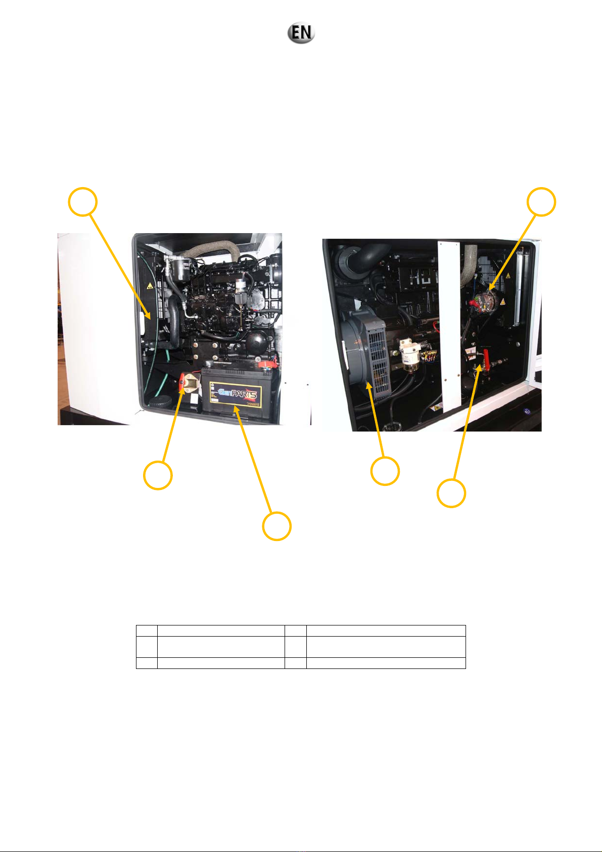
Figure 8 : General description of the generating set (Continuation)
1 Protective grille 4 Alternator
2 Battery isolating switch 5
External fuel supply combined tap
(optional)
3 Starter battery 6 Charging alternator

17/242
Control
4
1
2
3
Figure 9 : General description of the generating set (control)
1 Control unit 4 Working hours counter
2 Emergency stop 5 Power circuit breaker
3 Socket control panel 6 Connection terminal block
Note : Photo presented with the Nexys control unit.
5
6

e
%
18/242
2.2. Technical specifications
Range / Generating set type RENTAL POWER / R33C3
Weights and Dimensions
Dimensions with high autonomy tank
Dimensions l x w x h
2200 mm x 1000 mm x 1528 mm
Weight:
1100 kg à vide / 1300 kg en ordre de marche
Hood:
M3127
Sound pressure level at 1 m
Measurement uncertainty : 0.66
Output
Voltage Hz Phase Load factor Max current (A)
400/230 50 3 0.8 48 26.4 / 33 24 / 30
(1) ESP: Stand-by output available for emergency use under variable charge up to 200hrs per year as per lSO 8528-1, no overload availabl
under these service conditions.
(2) PRP: Main output available continuously under variable load for an unlimited time peri od per year as per ISO 8528-1, an overload of 10
one hour every 12 hours is available, as per ISO 3046-1.
Term of use :
Standard reference conditions ESP/PRP 40° / 40°, Air Intlet Temp, 1000m / 1000m mA.S.L. 60 % relative humidity.
Engine data
Manufacturer / model MITSUBISHI S4S-Z361SD
Type 4 Cycles Naturally aspirated
Cylinder configuration 4 XL
Cubic capacity 3.33 L
Rotation speed 1500 Rpm
Max emergency/prime power at nominal speed 31.3 / 28.3 kW
Adjustment type Mechanical
Fuel consumption
100 % main power 8.60 L/h
Fuel
Fuel type Diesel
High autonomy fuel tank 220 L
Lubrication
Oil capacity 10 L
Min. Oil pressure 1 bar
Nominal oil pressure 3.9 bar
Oil consumption (100 % load) 0.08 L/h
Oil sump capacity 9 L
Type of lubricant Genlub
Cooling
Engine capacity with radiator 8.5 L
Max coolant temperature 105 °C
Fan power 0.8 kW
Refrigerant type Gencool
Thermostat 76.5 – 90 °C
: 72 dB(A)
Emergency
power
kW / kVA
1
Prime power
2
kW / kVA

19/242
Alternator data
● Compliant with NEMA MG21 standards, UTE NF C51 111,
VDE 0530, BS 4999, IEC 34.1, CSA
Type LEROY SOMER LSA42.2L9
Number of phases 3
Power factor (cos Phi) 0.8
Number of poles 4
Excitation type AREP
Regulation R438
Number of bearings 1
Coupling Direct
Control unit(s)
NEXYS
● The alternator is protected against short circuits
● Vacuum impregnation, epoxy winding, IP23 protection rating
TELYS
Standard specifications
:
Frequency meter, Voltmeter, Ammeter
Alarms and faults
:
Oil pressure, Coolant temperature, Fail to start, Overspeed,
Alternator min/max, Fuel level low, Emergency shutdown
Engine parameters
:
Working hours counter, Engine speed, Battery voltage, Fuel
Level, Air Preheating
Standard specifications:
Voltmeter, Ammeter, Frequency meter
Alarms and faults:
Oil pressure, Water temperature, Start failure, Overspeed,
Alternator min/max, Battery voltage min/max, Emergency stop
Engine parameters
:
Timer, Oil pressure, Water temperature, Fuel level, Engine
speed, Battery voltage

20/242
2.3. Identifying sets
Generating sets and their components are identified by means of identification plates.
The precise rules for identifying each major component (engine, alternator, etc.) are set out in each manufacturer's documentation
contained in the appendices of this manual.
1 - Generating set
2 - Manufacturer name
3 - Model
4 - Serial number
5 - Year of manufacture
6 - Rated output (kVA and kW) according to the ISO
8528-1 standard
PRP: main power
ESP: emergency power
7 - Rated power factor
8 - Maximum altitude of the site above sea level (m)
for the rated power
Figure 10 : Example of a generating set identification plate
9 - Maximum ambient temperature for the rated
power (°C)
10 - Rated frequency (Hz)
11 - Generating set rotation speed (RPM)
12- Rated voltage (V)
13 - Rated current (A)
14 - Weight (kg)
15 - CE marking
16 - Non CE standard marking
(e.g.: GOSSTANDART)
17 - Sound pressure
18 - Sound power

21/242
2.4. Fluid retention
Any outflow of the fluids contained in the generating sets (fuel, oil and coolant, or rainwater or condensation) will be collected in a
retention container.
The containers have a capacity which allows 110% of the fluids contained in the generating set fitted with this option to be collected.
Figure 11 : Fluid retention container
The generating sets are fitted with a visual alarm warning when the upper limit of the retention container has been reached.
In all cases, the retention containers must be regularly checked to ensure they contain no fluid (fuel, oil and coolant, or rainwater or
condensation). If necessary, drain the containers via the drain port.
Note: Never allow these fluids to drain onto the ground; ensure they are collected in a designated container.

22/242
2.5. Fuels, lubricants and coolants
All specifications (product features) are given in the engine and alternator maintenance manuals attached to this manual.
In addition to these, we recommend the fuels, lubricants and coolants mentioned in the "Specifications" section.
2.5.1 Fuel specifications
General quality requirements
The quality of the fuel is essential for engine performance. It affects the technical performances such as the service life, power supplied
and fuel consumption as well as the ability to respect the requirements issued by authorities relating to pollutant emissions. Only fuels
which conform to the current legal requirements and national and international standards should be used. Consult the local
fuel distributor to find out the characteristics of the diesel fuel available in the area.
Examples of standards and requirements:
EN 590
ASTM D 975 1-D and 2-D
European standard (CEN) for vehicle fuel - fuels for diesel engines (diesel fuel) requirements and test methods
American Society for Testing and Materials: basic requirement in the United States and
Canada
JIS KK 2204 Japanese Industrial Standards: Japanese industrial standards
Respecting pollutant emissions
The certification measures confirming that the legal emission value limits are respected are performed with certified fuels which
conform to the standards and requirements stated above.
Resistance to low temperatures
When the external temperature is low, the fluidity of diesel fuel may no longer be sufficient due to paraffin deposits. Also, in the winter
in order to avoid malfunctions (for example, clogged filters), use diesel fuels which are fluid enough in cold weather.
The requirements to respect for the various geographical regions and various seasons (winter/summer) are specified in the standards
and/or national regulations. Petrol companies should always supply fuels with the correct flow properties regardless of the time of year.
In general, diesel fuel is treated with additives so that the fuel can be used at low temperatures in the region where it is marketed.
Treating fuel with additives must respect the engine manufacturer's recommendations and maintain a suitable lubricity for the injection
systems. It is recommended to favour fuels whose additives have been added in a refinery over those modified in the storage tank.

23/242
General specifications for diesel fuel
The fuel used must have the following characteristics (non-exhaustive list):
The sulphur content must meet the current emissions regulations in the region where the
generating set is used.
For the United States and countries respecting the EPA regulation
Only use Ultra Low Sulphur Diesel (ULSD) fuel with a maximum sulphur content of 15 mg/kg
for Interim Tier 4 and Tier 4 certified engines.
Sulphur content
For the European Union
Directive 2009/30/CE whose aim is to limit atmospheric pollution, imposes the use of a diesel
fuel with a very low sulphur content of 10 mg/kg, for non road mobile machinery
In France, this obligation has resulted in the development of a diesel fuel called "off road diesel
fuel" or "GNR". The maximum admissible sulphur content is 10 mg/kg. However, member
states allow these diesel fuels to contain up to 20 mg/kg of sulphur when they are distributed
to the final users. It is recommendable to avoid storing off road diesel fuel for long periods of
time (over 6 months).
The viscosity and density directly affect the performance (power and fuel consumption),
emissions and service life of the engine. A low level of viscosity and density reduces engine
power and increases fuel consumption. Too high a level of viscosity and density seriously
Viscosity and
reduces the service life and operation of the fuel injection system.
density
In order to maintain adequate technical and environmental performance, the viscosity and
density must conform to the specifications indicated in the manufacturer's instructions for the
engines fitted to our generating sets.
Lubricity (or
capacity for
lubrication or
oiliness)
In order to protect the fuel injection system against excessive wear, the fuel must have
satisfactory lubricity (refer to the manufacturer's instructions for the engines fitted to our
generating sets).
The ignition behaviour of diesel fuels is described by the cetane index. The cetane index is
Cetane index
important for emissions, the ability to start in cold weather and engine noises. The minimum
technical requirements are 45.
.
The fuel and tank must not contain any water. Water causes the engine parts to corrode and
wear more rapidly, particularly the injection system parts. In addition, water promotes the
Water and
contaminants
growth of bacteria and fungi in the tank, which can clog the fuel filter. The fuel must not contain
any type of residue. Organic contaminants (bacteria, fungi, etc.) can block the fuel filters;
inorganic material in the fuel (dust, sand) can cause serious damage to the injection
equipment.

24/242
2.5.2 Lubricant specifications
Essential for the correct operation of the engine. The oil should be selected according to its use. Besides the lubrication function, oil
should also:
- cool certain parts;
- protect metal parts against corrosion;
- improve the sealing, in particular between pistons, piston rings and cylinders;
- remove impurities (to the filter).
It is recommendable to use a top of the range lubricant for diesel engines. The table below lists the oils recommended for each engine
manufacturer.
Engine
Make Type Make Type
Cummins All GenPARTS GENLUB TDX 15W40
John Deere All
MTU All GenPARTS GENLUB TDX 15W40
Mitsubishi All GenPARTS GENLUB TDX 15W40
Fuel GenPARTS GENLUB TDX 15W40
Perkins
Gas MOBIL PEGASUS 705
Volvo All GenPARTS GENLUB TDX 15W40
Doosan All GenPARTS GENLUB TDX 15W40
Lombardini
All
Kohler
John Deere John Deere PLUS-50
GenPARTS GENLUB TDX 15W40
GenPARTS
or Kohler
GENLUB TDX 15W40 or Kohler 5W40,
according to the model of the engine
Viscosity
Viscosity is a measure of the flow resistance of a fluid. The viscosity of an engine oil is expressed by 2 SAE (Society of Automotive
Engineers) grades. One grade for cold weather and one grade for hot weather. The grade for cold weather appears before the letter W.
The 1st grade represents dynamic viscosity in cold weather, namely the ability to start the engine and to prime the oil pump (and
therefore to lubricate the various components quickly). The lower the number, the more fluid the oil.
The 2nd grade represents the kinematic viscosity in hot weather. The higher the number, the thicker the film of oil when hot (which aids
protection and sealing). The lower the number, the less friction there will be in hot weather (it helps to save fuel).
In order to ensure immediate protection when starting the engine, the choice of viscosity grade when cold is essential. More fluid oil is
quicker to flow when oil begins to circulate through the engine. It should be selected according to the ambient temperature. See the
table below.

25/242
Characteristics of GENLUB TDX 15W40 oil
Performance
GENLUB TDX oil is a 15W40 multigrade mineral oil which meets the following specifications: ACEA E3 and API CG-4.
ACEA E3: oil with superior viscosity stability, suited to extended oil change intervals and severe conditions of use.
API CG-4: oil particularly effective to meet the emissions requirements.
ACEA = European Automobile Manufacturers' Association
API = American Petroleum Institute
Specifications
Specifications Units Grade SAE 15W-40
Density at 15°C kg/m3 883
Kinematic viscosity at 100°C mm2/s (cSt) 14
Viscosity index – 130
Flow point °C - 27°
Flash point °C >200
TBN* mgKOH/g 9.7
Typical values given for information purposes
* TBN (Total Base Number – degree of alkalinity): a measure of a lubricant's reserve alkalinity according to standard ASTMD 2896.
This check makes it possible to assess the ability of the product to remain in service and to check the ’capacity of the lubricant to
neutralise the acidity contained in the oil, which may corrode the metallic elements of the lubricated component.
2.5.3 Coolant specifications
The engine's internal cooling system allows the engine to operate at a precise temperature.
The table below lists the coolants recommended for each engine manufacturer.
Engine
Make Type Make Type
Mitsubishi LLC
Mitsubishi All
GenPARTS GENCOOL PC -26
MTU All GenPARTS GENCOOL PC -26
John Deere All GenPARTS GENCOOL PC -26
Volvo All GenPARTS GENCOOL PC -26
Doosan All GenPARTS GENCOOL PC -26

26/242
Specifications of GENCOOL PC -26 coolant
Performance
GENCOOL PC -26 coolant is a ready-to-use cooling fluid which provides a high level of protection and is produced from an antifreeze
approved by the majority of manufacturers (Power Cooling concentrated antifreeze).
It offers the following:
- Improved anticorrosion: improves the effectiveness and service life of the cooling system.
- High temperature feature: promotes heat exchange.
- Long-term protection: against overheating and corrosion under extreme conditions of use.
- Compatible with the original fluid (however, it is recommended to drain the entire cooling system when replacing the fluid).
Specifications
Specifications Units Characteristics
Density at 20°C kg/m3 1053 ± 3
pH pH 7.5 to 8.5
Alkalinity reserve ML ≥ 10
Boiling temperature °C 105 ± 2
Freezing temperature °C -26 ± 2
Typical values given for information purposes

27/242
3. Transporting the equipment
3.1. Warnings concerning transport
It is prohibited to operate generating sets whilst they are being transported.
IMPORTANT
3.2. Preparing for transport
Before the equipment is transported, perform the following operations:
1. Close the tap on the oil top up tank outlet.
2. Fill up the oil top up tank with oil.
3. Fill up the crankcase with oil.
4. Fill up the on-board tank with fuel.
5. Check that the batteries are fitted and filled with electrolyte.
3.3. Road transport
3.3.1 Generating sets with and without an enclosure
Generating sets must be transported by road in accordance with the regulations of the countries concerned.
When transporting generating sets in containers by road, the following steps must be observed:
1. Put a plastic cover over non-enclosed generating sets during transportation.
2. Select transport equipment (trailer, semi-trailer, etc.) suitable for this usage and having all the safety guarantees in terms of
load bearing capacity and of the securing devices.
3. Chock and fix the generating sets to the floor of the transport equipment.
4. Strap the generating sets to the transport equipment.
5. Select a transport route which makes it possible to travel on roads suitable for vehicles, and whose quality will not damage the
on-board generating sets.

28/242
3.3.2 Generating sets on trailers
3.3.2.1. Hitching and unhitching the trailer
Jockey wheel for
M3126
and M3127
type trailers
Before hitching the trailer, check the hitching system on the towing vehicle; this must be perfectly compatible with the trailer.
Jockey wheel for
M3128
and M3129
type trailers
Towing a trailer with a non-compliant device (bar, cables, lashing, etc.) runs the risk of serious accidents.
IMPORTANT
Also check:
- That there are no incipient ruptures or significant wear on the hitching system.
- That the locking system is working properly.

29/242
Hitching a trailer fitted with a hitching ring
1. Drive the towing vehicle or bring the trailer up to the hitching point, then:
- With the jockey wheel touching the ground, place the stabiliser (1) in the top position:
Loosen the jaw of the stabiliser (2) with its lever;
Raise the stabiliser fully;
Tighten the jaw of the stabiliser (2) with its lever.
- Remove the wheel chocks if necessary and store them.
2. Position the trailer parallel to the ground using the guide wheel handle (jockey wheel).
3. Place the hitching ring above the towing vehicle's hitching system:
After this adjustment, the trailer must remain parallel to the ground.
Make any necessary height adjustments to the towbar using the jockey wheel to enable hitching.
IMPORTANT
2
1
- Remove the safety pin from the towbar (3);
- Undo the nut with the lever (4);
- Use the adjustable towbar handle to place the ring above the hitching system;
- Tighten the nut to lock the towbar;
- Fit the towbar safety pin.
4. Attach the ring to the hitching system:
- Lower the trailer by moving the jockey wheel away from the ground using
its handle (5).
5. Lock the jockey wheel in the towing position:
When in the towing position, the jockey wheel must not:
- obstruct the unlocking cable's movement;
- trap any electrical cables.
IMPORTANT
M3126/M3127 type trailers
- Position the jockey wheel at the rear.
- Raise the jockey wheel with its handle (5) into the
notches on its tube (6).
- Loosen the jaw of the tube (7) with its lever.
- Raise the tube fully.
- Tighten the jaw of the tube (7) with its lever.
6
5
7
4
3
5
M3128/M3129 type trailers
- Remove the safety pin from the position lock (8).
- Remove the position lock (8).
- Place the jockey wheel in the towing position.
- Fit the position lock (8).
- Fit the safety pin in the position lock (8).
- Raise the jockey wheel with its handle fully and at right
angles to the towbar.
8

30/242
6. Attach the unlocking cable to the hitching plate on the towing vehicle.
Examples of how to attach the hitching cable
If the hitching ring is not correctly connected to the hitching hook, the trailer will become separated from the
IMPORTANT
towing vehicle. In this case the unlocking cable actuates the parking brake (which then becomes an emergency
brake).
To ensure that the device fulfils its function correctly, the unlocking cable:
- MUST NOT be wound around the jockey wheel, as this will disable emergency braking;
- MUST NOT be taut or obstructed, as this could activate emergency braking during towing;
- MUST be routed as straight as possible and not be obstructed at any point;
- MUST be sufficiently long to allow cornering.
7. Connect the electrical cable plug controlling the lamps, indicators, etc. to the socket on the towing vehicle.
8. Remove the parking brake:
- Remove the wheel chocks if necessary and store them;
- Perform the following operations simultaneously on the parking brake:
Press the unlocking button (9);
Lower the handle (10) fully.
9
10

31/242
Unhitching a trailer fitted with a hitching ring
1. Immobilise the trailer:
- Chock the wheels;
- Apply the parking brake:
Raise the parking brake lever (10) fully.
2. Disconnect the electrical cable plug controlling the lights, indicators, etc. from the socket on the towing vehicle.
3. Remove the unlocking cable on the towing vehicle.
4. Release the hitching ring:
M3126/M3127 type trailers
- Disengage the jockey wheel from the notches in the
tube (6) with its handle (5).
- Loosen the jaw of the tube (7) with its lever.
- Lower the tube until the jockey wheel touches the
ground.
- Tighten the jaw of the tube (7) with its lever.
6
5
7
- Support the load on the jockey wheel:
Lower the jockey wheel with its handle;
When you are sure that the wheel can bear the load (the towbar rises), unhitch the trailer from the vehicle.
5. Fit the stabiliser (1):
- Loosen the jaw of the stabiliser (2) with its lever;
- Place the stabiliser in contact with the ground;
- Tighten the jaw of the stabiliser (2) with its lever.
- Remove the safety pin from the position lock (8) on the
jockey wheel.
- Remove the position lock (8).
- Place the jockey wheel in the bottom position.
- Fit the position lock (8).
- Fit the position lock pin.
- Lower the jockey wheel to the ground with its handle.
M3128/M3129 type trailers
8
1
2

32/242
3.3.2.2. Check before towing
Before first use, it is essential to check the tightness of the wheel bolts.
IMPORTANT
Before towing, check the following:
- Wheel tightness.
- Hitching hook locked.
- Tyre pressure.
- Signalling lights working.
- Enclosure doors closed.
- Parking brake released.
- Guide wheels (jockey wheels) and stands lifted and locked.
- Safety cable fitted.
INFLATION PRESSURE (BAR)
145R13 2.2 185R14C 4.5
155 / 70R13 2.5 195R14C 4.5
185 / 70R13 2.5 215R14C 4.5
175R14C 4.5 215 / 75R14C 4.5
TIGHTENING TORQUE WHEELS
Axis of 10 60 Nm
Axis of 14 and 16 120 Nm
3.3.2.3. Operation
The driving speed must be suited to the condition of the road and the handling of the trailer.
Maximal speed on road: 140km/h.
Driving at high speed causes the tyres to heat; it is therefore important to stop from time to time and check them. Excessive heating
may cause a puncture, and therefore a serious accident. For reversing manoeuvres, remember to lock the inertia brake.
Particular attention must be paid to the tightness of the wheels on new vehicles.
IMPORTANT
In the first few miles' driving, heating of the brake hubs and drums will actually reduce the wheel tightness. It
is therefore essential to check the tightness every 6 miles (10 kilometres) until no further loosening is noted.
The tightness check must nonetheless be carried out whenever you have towed the trailer.

(
33/242
Lights / signalling
Warning lights are obligatory for on-road driving. Signalling must comply with regulations in force in the country of use.
Red rear lights
+ direction indicators
+ stop lights
Rear reflective devices
red triangle)
Front reflective devices (white)
Side reflective devices (orange)
Figure 12 : Example of French signalling
3.4. Rail transport
3.4.1 Generating sets with and without an enclosure
Generating sets must be transported by rail in accordance with the specific rules governing rail transport.
When transporting generating sets in containers by rail, the following steps must be observed:
1. Put a plastic cover over non-enclosed generating sets during transportation.
2. Choose transport equipment appropriate for this usage, and having all the safety guarantees both in terms of load-bearing
capacity and securing devices.

34/242
3.5. Shipping
3.5.1 Generating sets with and without an enclosure
Transportation must be carried out in accordance with the rules of shipping. Generating sets must be transported in a shipping
container.
When shipping generating sets in containers, the following steps must be observed:
1. Choose transport equipment appropriate for this usage, and having all the safety guarantees both in terms of load-bearing
capacity and securing devices.
2. In the case of a grouped load container, SEI cases must be used for packing.
3.6. Air transport
Containers must be transported by air in accordance with the specific rules governing air transport.
The UN has classified generating sets as "dangerous goods" listed under UN code 3166 - class 9 - "Engine, internal combustion
(flammable liquid powered)".
Any air shipment of generating sets must be subject to prior declaration to the air freight company, in accordance with form MOD3909.
For air transport, observe the following steps:
1. Choose transport equipment appropriate for this usage, and having all the safety guarantees both in terms of load-bearing
capacity and securing devices.
2. For control boxes, packing in an SEI 4 C case (solid case with waterproof cover) is obligatory.

35/242
4. Installation - Connections
4.1. Unloading the generating set
4.1.1 Choosing the location
When choosing where to site the generating set, bear in mind the:
- proximity to the electrical distribution panel;
- nuisance caused by the noise;
- fuel supply;
- burnt gas evacuation;
- direction of these gases and the noise generated.
1 m min.
Incorrect ventilation and exhaust Building or terrain too rough
Generating set incorrectly seated
Impossible to open enclosure doors Impossible to fill with fuel
Figure 13 : Examples of problems that may be encountered

36/242
4.1.2 Safety during unloading
Always follow the safety instructions before unloading
IMPORTANT
- The lifting machinery or equipment is suitable for the work required and the weight of the generating set. This is indicated on the
generating set's identification plate.
- The sling is correctly positioned in the central lifting eye or the lifting arms are correctly positioned in the fork-lift pockets intended
for this purpose.
- The ground is able to bear the load of the generating set and its lifting machinery without stress (otherwise lay down stabilising
beams of sufficient strength).
- The generating set is put down as close as possible to its place of use or transport, in a clear space with free access.
Example of equipment to be used:
crane;
slings;
lifting beam;
safety hook;
shackles;
Forklift truck.
4.1.3 Unloading the generating set
Before unloading or moving generating set, check that the handling equipment used is able to bear the weight of
IMPORTANT
the generating set (shown on the generating set's identification plate.
4.1.3.1. Slings
1. Attach the sling on the lifting equipment to the ring on the generating set (no. 1) provided for this purpose. Tension the slings
slightly.
2. Check that the sling is correctly attached and the equipment is steady.
3. Lift the generating set carefully.
4. Direct the generating set towards the chosen location and stabilise it.
5. Carefully set down the equipment while continuing to position it.
6. Release the sling, then detach it.

37/242
4.1.3.2. Fork lift truck
1. Position the arms of the forklift truck in the forklift pockets (no. 2).
2. Lift the equipment, handling it gently.
3. Set down the generating set in its unloading position.
3
1
2
3
Figure 14 : Points used for lifting and moving
4.1.4 Moving the generating set
Whenever moving the generating set, ensure suitable equipment is used (e.g. sling, forklift, etc.) and identify those parts on the
generating set which can be used to move it:
- lifting eye (no.1);
- forklift grooves (no.2);
- tow bar (no.3).

y)
38/242
4.2. Connecting the generating set
4.2.1 Connection summary
This diagram can be used to retrace the different steps enabling the generating set to be correctly connected.
Identify the type of differential protection
TT earthing system
TT
fitted on the generating set
"EDF application" option (France
onl
Fixed differential protection Adjustable differential protection
30 mA 30 mA 300 mA 300 mA
No operation required:
terminal circuits protected
Add differential protection
set to 30 mA to the terminal
circuit output(s)
Set the differential protection
of the generating set
No operation required:
terminal circuits protected
Add differential protection
set to 30 mA to the terminal
circuit output(s)
Earth the generating set
Connect the generating set to the installation

39/242
4.2.2 Protecting people and equipment
4.2.2.1. Earthing system principle
The Earthing system, or SLT (formerly Neutral system) of the electrical installation defines the situation of the generating set neutral
in relation to earth and the grounds of the electrical installation at the user end.
Our generating sets are designed to operate with the TT system (or EDF application depending on the option, for France only).
4.2.2.2. TT system
In the TT earthing system, automatic power cut-off via a Residual Current Device (RCD) is obligatory at the upstream part of the
installation, to ensure that personnel are protected (additionally, a maximum 30 mA device must be installed on outlet circuits).
R
id
id
R
Ph 1
Ph 2
Ph 3
N
PE
R
Neutral connected
to earth
T
Ground connected
to earth
T
R
Ph 1
Ph 2
Ph 3
N
PE
R
Neutral earth
Ground earth
id
Equipment
Figure 15 : TT earthing system
The alternator neutral is earthed, the grounds of the user equipment have their own earth connection.

40/242
4.2.2.3. Installing the differential protection
The generating set is equipped with a residual current device in order to guarantee individuals are protected from electric shocks with
the TT system. This may be fixed ("vigi" unit) or adjustable (Resys) depending on the option chosen.
• If the generating set's residual current device is fixed and the activation threshold is set to 30 mA, it is guaranteed to protect people.
• If the generating set's residual current device is fixed and the activation threshold has been set at 300 mA, a 30mA residual current
device must be added to each of the circuit outlets in use.
• If the generating set's residual current device is adjustable, (located upstream) this must be above those devices located
downstream (terminal circuits); this means that continuity on clean circuits will be maintained in the event of a fault on one of the
terminal circuits (see the following point on setting the residual current device).
Example:
0.03A
30mA
0.3A
(300mA)
Residual current device
Terminal circuit 1
0.03A
30mA
Risk of electric shock.
The generating set's differential relay is factory-set with a current threshold of 0.03 A (30 mA) and with an
automatic time delay (0 s).
Any change to the setting on the residual current device could pose a risk to personal safety. The user will be held
liable - any changes must only be made by trained, qualified engineers.
If the setting is modified, it is essential to restore the original settings after use.
Generating set
Generating set's residual
current device
Residual current device
Terminal circuit 2
0.03A
30mA
Residual current device
Terminal circuit 3

(1)
41/242
4.2.2.4. Setting the generating set differential protection
The setting of the generating set's residual current device is guaranteed by a differential relay fitted near the control unit (type A / AC or
B depending on the generating sets). As a result, two parameters relating to the downstream device (terminal circuit) must be set:
- Current threshold: the generating set's differential relay must be three times more sensitive than that of the terminal circuit.
- Time delay: the cut-off of the generating set's differential relay must be longer than that of the terminal circuit.
- Type A / AC differential relay:
Use:
Setting:
Differential relay for which operation is guaranteed:
• for residual sinusoidal alternating currents;
• for continuous pulsed residual currents;
• for continuous pulsed residual currents with a continuous component of 0.006 A with or without phase check,
independent of the polarity.
1. Use a screwdriver to set the current
threshold potentiometer (1) to 0.03 A (30
mA).
2. Use a screwdriver to set the time delay
potentiometer (2) to 0s (automatic).
3. Test the residual current device using the
"Test" button on the relay (3).
Time setting potentiometer
Test Button
(3)
(2)
Current threshold potentiometer

42/242
- Type B differential relay:
Use:
Differential relay for which operation is guaranteed:
• as in the case of type A;
• for residual sinusoidal currents up to 1000 Hz;
• for residual sinusoidal currents superimposed on a pure continuous current;
• for continuous pulsed currents superimposed on a pure continuous current;
• for residual currents which could come from rectifier circuits i.e.:- three phase half-wave rectifier or a three-phase full-
wave bridge rectifier, full-wave bridge rectifier between phases, with or without phase angle check, independent of
the polarity.
Setting:
1. Use a screwdriver to adjust the current
threshold using the setting potentiometer
(1) and the micro-switches (4)
to 0.03 A (30 mA).
2. Use a screwdriver to adjust the time delay
using the setting potentiometer (2) and the
micro-switches (4) to 0s (automatic).
3. Test the residual current device using the
"Test" button on the relay.
Risk of electric shock.
The generating set's differential relay is factory-set with a current threshold of 0.03 A (30 mA) and with an
automatic time delay (0 s).
Any change to the setting on the residual current device could pose a risk to personal safety. The user will be held
liable - any changes must only be made by trained, qualified engineers.
DANGER
If the setting is modified, it is essential to restore the original settings after use.
Test Button
(3)
Sensitive area (4)
(white = position of micro-
switches)
Time setting
potentiometer (2)
Current threshold potentiometer
(1)

43/242
4.2.2.5. Earthing the generating set
Risk of electric shock.
Before use, the generating set must always be earthed. Protection against electric shocks is only effective
once the earthing connection has been made.
DANGER
1. Open the door to the power section (no.1) then the access
door to the cable router flap and to the connection terminal
box (no.2).
Disconnect the battery leads, starting with the negative lead (-), or use the battery isolating switch before
carrying out any operations on the generating set.
1
2
2. Connect the earth cable (supplied) to the terminal (rep.3)
on the generating set located on the connection terminal
box.
3

44/242
3. Check the length of the earthing rod depending on the
nature of the ground and adapt if necessary.
The equipment supplied is not suitable for
IMPORTANT
bare stony soils, dry sand or impermeable
rock.
4. Plant the earthing rod in the ground and connect it to the
earth cable.
Nature of ground
Thick arable land, damp
compact backfill
Thin arable land, gravel, rough
backfill
Bare stony soils, dry sand,
impermeable rock
Length of earthing
rod (in metres)
1
1
4 or 4 x 1
Earth cable
ground
1 meter
Note: For the United States (National Electrical Code ref. NFPA-70), use a copper wire with a minimum cross-section of 13.3 mm² (or
AWG 6 at most) connected to the generating set's earth connection and a galvanised steel earthing rod completely buried in the ground
in an upright position. This earthing rod must be at least 2.5 m long (of which at least 1 m must be in the ground).
4.2.3 Making the connections
4.2.3.1. Connections - general information
When connecting, always comply with standard NFC 15-100 and the application guide NFC 15-401 (in France) or follow standards
based on the international standard IEC 60364 (countries outside France).
The cable cross-section and number of connection cables should be determined according to the type of connection cable and the
current standards to be observed in the country of installation. The choice of connection cables must comply with international standard
IEC 60364-5-52.

45/242
4.2.3.2. Selecting the power cables
The calculation rules used to choose the power connection cable size are defined below:
- Identify the current shown on the generating set's identification plate.
- From the table below, select the circuit breaker rating directly above the current shown on the generating set's identification
plate.
- Choose the corresponding cable size.
.
Three-phase
Permitted drop in voltage = 5% / Multi-core conductors or connected single-core conductors where rating = 4X…(1) / Cable type
PVC 70°C (e.g. H07RNF) / Ambient temperature = 30°C.
Circuit breaker
rating
(A)
0 - 50m 51 - 100m 101 - 150m
mm²/AWG* mm²/AWG* mm²/AWG*
10 1.5 / 14 2.5 / 12 4 / 10
16 2.5 / 12 4 / 10 6 / 9
20 2.5 / 12 4 / 10 6 / 9
25 4 / 10 6 / 9 10 / 7
32 6 / 9 6 / 9 10 / 7
40 10 / 7 10 / 7 16 / 5
50 10 / 7 10 / 7 16 / 5
63 16 / 5 16 / 5 25 / 3
80 25 / 3 25 / 3 35 / 2
100 35 / 2 35 / 2 4X(1X50) / 0
125 (1) 4X(1X50) / 0 4X(1X50) / 0 4X(1X70) / 2/0
160 (1) 4X(1X70) / 2/0 4X(1X70) / 2/0 4X(1X95) / 4/0
250 (1) 4X(1X95) / 4/0 4X(1X150) / 2350MCM 4X(1X150) / 2350MCM
400 (1) 4X(1X185) / 0400MCM 4X(1X185) / 0400MCM 4X(1X185) / 0400MCM
630 (1) 4X(2X1X150) / 2x 2350MCM 4X(2X1X150) / 2x 2350MCM 4X(2X1X150) / 2x 2350MCM
Single phase
Permitted drop in voltage = 5% / Multi-core conductors / Cable type PVC 70°C (e.g. H07RNF) / Ambient temperature =30°C.
Cable sizes
Circuit breaker
rating (A)
0 - 50m 51 - 100m 101 - 150m
mm²/AWG* mm²/AWG* mm²/AWG*
10 4 / 10 10 / 7 10 / 7
16 6 / 9 10 / 7 16 / 5
20 10 / 7 16 / 5 25 / 3
25 10 / 7 16 / 5 25 / 3
32 10 / 7 25 / 3 35 / 2
40 16 / 5 35 / 2 50 / 0
50 16 / 5 35 / 2 50 / 0
63 25 / 3 50 / 0 70 / 2/0
80 35 / 2 50 / 0 95 / 4/0
100 35 / 2 70 / 2/0 95 / 4/0
125 50 / 0 95 / 4/0 120 / 2250MCM
* : AWG. American Wire Gauge, American standard for electrical cables.
Cable sizes

46/242
4.2.3.3. Connecting the generating set to the installation
Risk of electric shock.
Before use, the generating set must always be earthed . Protection against electric shocks is onl y effecti ve
once the earthing connection has been made.
DANGER
1. Open the door to the power section (no.1) then the
access door to the power connection cable router flap
and to the connection terminal box (no.2).
Disconnect the battery leads, starting with the negative lead (-), or use the battery isolating switch before
carrying out any operations on the generating set.
2
1
2. Loosen the two knobs (no.3) of the power connection
cable router flap then slide the flap (no 4) towards the
outside of the generating set.
3. Feed the power connection cables through the cable
router flap.
4
3
3
Power cables

47/242
4. Connect the power connection cables onto the bars
(N/L0-L1-L2-L3 or N2-R2-S2-T2) using the terminals (no.5) or
clamps (no.6).
5. Slid e the cable router flap towards the inside of the generating
set until it makes contact with the power connection cables then
retighten the two knobs; close the access door to the power
section back up again.
6. Con nect the power connection cables to the installation to be
powered ensuring the live and neutral wires are correctly
connected.
Our generating sets are factory-set with a
conventional direction of phase rotation. A
IMPORTANT
phase converter (not supplied) can be used to
ensure correspondence of phases between
the generating set and the installation..
5
3
6
4
3
N/L0
ou
N2
L1
L2
ou
R2
ou
S2
L3
ou
T2
Installation to be powered
(e.g.: cabinet, distribution
box, installation etc.)
To limit the risk of falls caused by obstacles on the floor, it is recommended to suspend cables and ventilation
ducts. As necessary, ensure that cables which remain on the floor are protected by burying or covering them.
IMPORTANT

48/242
4.2.3.4. Connecting the battery or batteries to the generating set
Always ensure that the polarities of the battery and starter motor correspond. Never swap the positive and
IMPORTANT
4.2.4 Overvoltage
Generating sets are not equipped with devices that protect against voltage surges from atmospheric discharges or due to handling
operations.
negative battery terminals when connecting them. This could cause severe damage to the electrical equipment.
To connect the battery:
1. Connect the red connecting cable (+) to the positive battery terminal.
2. Then connect the black cable (-) to the negative battery terminal.
To disconnect the battery:
1. First disconnect the black cable (-)
2. Then disconnect the red cable (+).
The company disclaims all liability for any accidents caused by these phenomena.
However, it is possible to install surge protectors considering that this assembly does not provide complete protection.
5. Installation
5.1. Warnings concerning commissioning
The inspections referred to in this section enable the electrical generator set to operate.
Specific skills are required to carry out these operations.
IMPORTANT
They must only be entrusted to personnel with the necessary skills.
Failure to follow these instructions in any way could result in malfunction or very serious accidents.
5.2. Checking the generating set installation
- Check the position of the generating set (stability, mounting, available space, ventilation, exhaust, etc.).
- Check the electrical connections :
earthing;
electrical control connections;
electrical power connections;
starter battery charging system (rating and voltage) if fitted to the generating set.

49/242
5.3. Preparing for operation of the generating set
- Become familiar with the controls useful to operate the generating set.
- Read and understand the "user" menus of the control unit.
- Become familiar with the maintenance plans for the generating set .
- Become familiar with the operation of the generating set at no load or under load.
- Become familiar with the fluid specifications (fuel, lubricant and coolant).
5.4. Checking the generating set before startup
- Check that the plugs, blanking covers and protective adhesive strips have been removed.
- Ensure that the anti-humidity bags have been removed from the electrical sections (cabinet or control console, alternator, etc.).
- Check the insulation of the alternator see the alternator's maintenance manual.
- Check the levels see the engine's maintenance manual:
coolant;
oil;
fuel.
- Open the oil filler tap (if fitted to the generating set).
- Check the starter battery or batteries (connecting and charge) see the paragraph entitled "Starter batteries".
- Check the starter battery charging system (if fitted to the generating set).
5.5. Checking the generating set after startup
Off-load tests
- Carry out the safety checks (emergency shutdown, oil pressure, coolant temperature, etc.).
- Check the mechanical parameters:
engine parameters (oil pressure, coolant temperature);
absence of abnormal vibrations;
absence of abnormal noises;
absence of leaks.
- Check the electrical parameters:
voltage, frequency, current;
rotating field.
On-load tests
- Check the mechanical parameters:
engine parameters (oil pressure, coolant temperature);
absence of abnormal vibrations;
absence of abnormal noises;
absence of leaks.
- Check the electrical parameters:
voltage, frequency, current;
rotating field.

50/242
6. Using the generator set
6.1. Pre-Start Inspection
Inspecting the engine compartment
Make sure there is no combustible material near the engine or battery. Also, check to
make sure that the engine and battery are clean. If combustible materials or dust are
found near the engine or battery, remove them.
Check the electrical wiring for such components as the starter and alternator for
looseness
Check the entire engine for fuel leakage, engine oil or coolant. If leakages are found,
repair.
Make sure the following valves, plugs and cocks are open or closed (tightened) properly:
Fuel feed valve: Open
Coolant drain cock (plug): Closed (Tightened)
Oil drain valve: Closed
Checking the engine oil level
- Do not top up the oil if the oil level is not below the low level marker.
Important
Pull out the oil level gauge and wipe it clean using a waste cloth.
Insert the oil level gauge fully into the oil level gauge guide, then pull out the gauge again.
The proper oil level is between the high and low marks on the oil level gauge. If the oil level is low, add engine oil of the specified
type.
Install the oil filler cap after refilling.
Check the oil pan and other area for oil leakage.

51/242
Checking the coolant level
Remove the radiator filler cap only after the engine has cooled to room temperature. Place a waste cloth
over the cap, and loosen the cap about a half-turn or stand the lever to the upright position to release
internal pressure. Never open the radiator filler cap while the engine is hot, otherwise the steam or hot
Warning
coolant spurts out and you may be scald with it.
Open the radiator filler cap and check the coolant level.
If the coolant level is low, add coolant to the speci-fied level.
Check for leaks in the cooling circuit.
Checking the air filter
A clogged filter element limits the engine's air intake and a reduced air supply to the engine.
Important
If the air filter is fitted with a dust control valve (A), press the tip
of the valve to evacuate any accumulated dust particles.
Check the air filter clogging indicator (B). If the indicator is red,
clean the air filter.
B
A

52/242
Checking the fuel pre-filter
The fuel is highly flammable and its vapours are combustible.
The fuel pre-filter must only be bled when the engine is stopped and cold.
Danger
Check that there is no water or sediment at the bottom of the pre-filter.
If necessary, drain the pre-filter using the following procedure:
Place a suitable container under the drain plug prefilter
Undo the drain plug (A) at the bottom of the pre-filter by two or three turns.
Collect the water and/or sediment in the container.
When fuel starts to flow out, tighten the drain plug.
Check that there are no leaks.
If necessary, reprime the fuel circuit.
A

53/242
6.2. Generator set with NEXYS control panel
6.2.1 Control panel presentation
7
9
9
2
3
9
4
1
6
5
Figure 16 : View of the front side
10
8
9
Emergency stop button for switching off the generating set in the event of a fault which could endanger personnel or damage
equipment
Key switch for starting up/shutting down the module and RESET function
Electronic card protection fuse
Screen-scroll button, press successively to access the various screens which are available
STOP button, press to switch off the generating set
START button, press to switch on the generating set
Normal operation LEDs and alarm and fault warning LEDs
Slot reserved for panel fascia options
Mounting bolt.
LCD for displaying alarms and faults, operating states, electrical and mechanical quantities

54/242
1 2 3 4 5
Figure 17 : Description of the LEDs
A lit LED indicates:
Module being supplied (green, lights up and remains lit)
Emergency stop activated (control panel or external emergency stop) (red, lights up and remains lit)
Visualisation of starting phase and speed/voltage stabilisation (flashing) and generating set operating OK or set ready to
generate (green, lights up and remains lit)
General alarm (orange, flashing)
General fault (red, flashing).
6.2.1.1. Introduction to pictograms
The pictograms are as follows:
Operating temperature
Fuel
Overspeed
Non-starting fault
Starting on external command
Preheating
Air intake
Figure 18 : View of pictograms
The "fuel level" pictogram is used to display the fault, the alarm and the fuel level.
The "operating temperature" and "oil pressure" pictograms are used to display the fault and analog value
The "overspeed" and "non-starting fault" pictograms are used to display the fault.
The "battery" pictogram is used to display the "alternator charge" fault and to indicate the battery voltage.
Oil pressure
Symbols for electric and
mechanical sizes
Battery
Delay

55/242
6.2.2 Manual starting
Check that the generating set circuit breaker has triggered.
Danger
connect the generating set battery.
turn the key switch to the ON position (without forcing it)
All of the LEDs light up for 2 seconds, to confirm that they are operating correctly.
If the LEDs do not light up, check the protection fuse and replace it if necessary.
All the items on the screen are displayed for 2 seconds.
Only the "ON" LED remains lit to indicate that the module is powered up.
The following screen appears.
The first line displays the motor speed in RPM.
The second line displays the battery voltage in
volts (V).
Check the battery voltage (min. 12 V)
Press (once briefly) the green "START" button.
If the motor is equipped with an air preheating system, there is a 10-second delay before the motor starts (preheating
activation period).
The following screen appears
The third line displays the air preheating time
remaining (with pictograms representing a
resistor and an hourglass).
If the motor is not fitted with an air preheating system or once the preheating delay has elapsed, the engine starts up
(start of a cycle comprising 3 attempts to start up the engine).
The following screen appears.
The number of successive and automatic starting attempts is limited to 3.
Warning
Note: the LED flashes as soon as the START button is pressed and continues to flash until the frequency stabilises if
a "measurements" card has not been inserted and until the frequency and voltage stabilise if a "measurements" card has been
inserted.
Following stabilisation, the LED light comes on
continuously.

56/242
6.2.3 Switching off
trigger the circuit breaker located at the base of the centre console
Let the motor run under no load for 1 to 2 minutes to allow it to cool.
press the "STOP" button to stop the generating set.
switch off the MICS Nexys module by switching the key to "OFF" (without forcing it).
6.2.4 Alarms and faults
The appearance of a fault or an alarm causes the following
screen to be displayed (one or more pictograms or a fault
code along with the SOS message are displayed).
The user can access the following screens by pressing the key
The fault or alarm screen will disappear once the fault or alarm has been removed.
Only one fault is displayed on this screen (the fault which caused the generating set to stop).
If one or more faults have appeared after the first fault, they can only be displayed after the first fault has been reset
(press "Reset" as many times as the number of faults present).
Note: an alarm can appear at the same time as a fault.
6.2.5 Faults and alarms - Details
List of faults which will cause the generating set to stop and generate a pictogram
Associated pictogram
Oil pressure fault: Indicates that the oil pressure is incorrect
Associated pictogram
Engine temperature fault: Indicates that the engine
temperature is too high.
Associated pictogram
Non-starting fault: Indicates that there have been three
consecutive unsuccessful starting attempts.
Associated pictogram
Overspeed fault: Indicates an excessive generating set
running speed.
Associated pictogram
Low fuel level fault: Indicates the need to top up the fuel.

57/242
List of faults which will cause the generating set to stop and generate a fault code
Associated message
Low coolant level fault: indicates that the level of coolant is
low in the radiator (linked to a two second time delay).
Or
Overload or short-circuit fault (optional): with the circuit
breaker SD contact closing (overload or short-circuit), the
generating set switches off immediately also causing the
main circuit breaker to be triggered.
Additional fault linked to message opposite: is displayed in
the following two cases:
Differential fault (1)
insulation fault (2)
(1) Differential fault (optional): with a differential fault
causing the activation of the differential relay, the
generating set stops immediately also causing the
main circuit breaker to be tripped.
(2) Insulation fault (optional): with an insulation fault
causing the activation of the control unit performing
insulation, the generating set stops immediately.
Underspeed fault: indicates an incorrect rotation speed
(below 1000 rpm).
Emergency stop or external emergency stop fault
"STOP" fault activated if the "STOP" button is pressed
whilst the "AUT" LED is flashing to indicate that the
generating set is operating in automatic mode.
List of alarms associated with a pictogram
Low fuel level alarm: Indicates the need to fill up with fuel.
"Alternator charging fault" alarm indicates a problem
affecting the alternator charging rate.
Associated message
Associated message
Associated message
Associated message
Associated pictogram
Associated pictogram

58/242
6.2.6 MURPHY diagnostic module
The fault finding module (MDDM) is an indicator for analysis and fault finding designed and manufactured for reading information
available on the J1939 CAN Bus. The fault finding module is easy to use and will enable you to view the values of the various engine
parameters and engine operating status codes.
It shows two lines, each of 8 characters, on a backlit LCD display. Two scroll buttons enable you to navigate in the menus and
parameters. Two LEDs, one red and one orange, indicate the fault or alarm status of the engine or ECU.
LED
DISPLAY
SCROLL BUTTONS
A- Machine Parameters
The following parameters are available on the Murphy fault finding module:
- working hours counter
- engine speed
- battery voltage
- engine speed
- coolant temperature
- oil pressure
- fuel economy
- air manifold temperature
- actual consumption
- active status codes
- status codes recorded coming from the engine
- MDDM20 parameter configuration for display
- display of the engine configuration parameters
-etc. depending on the type of engine.
B-Use
The Murphy module (MDDM) offers simple menu navigation:
1.To browse the list of parameters, press the Up and Down buttons.
2.To enter or exit a sub-menu, press both arrows simultaneously.

59/242
The following diagram shows the structure of the main menu and how to go to each parameter:

60/242
The Parameter menu: to navigate in this menu simply use the arrow buttons separately.
The sub-menus: The sub-menus are available at the end of the parameter menu. To go to these sub-menus, scroll through the
parameters using the ▲ and ▼ buttons until you reach the required sub-menu.
C- The Sub-menus.
The sub-menus enable certain aspects of the fault finding module display to be modified.
Changing the unit of measurement:
There are two display modes available for units: English or metric. To change your units of measurement, use the ▲ and ▼ scroll
buttons until you get to the sub-menu:
Press the ▲ and ▼ arrows simultaneously if you want to retain the current designation.
Press one of the scroll buttons to show the second mode for displaying units. If you want to retain the second display mode, confirm
this by pressing the ▲ and ▼ buttons simultaneously.

61/242
D-Displaying the active service codes:
The fault finding module enables the machine faults and alarms to be displayed in real time. When a fault appears, the display shows
the message "SrvcCode" every five seconds between displaying the current parameters.
The orange LED will light up when an alarm code is displayed (engine does not stop), the red LED will light up when a fault code is
displayed.
SPN and FMI codes are used in standard J1939 to identify faulty equipment
SPN: Suspect Parameter Number.
FMI: Failure Mode Indicator.
In the event that there are no active fault codes, the following screen will appear:
Depending on the SPN/FMI code, refer to the attached "List of engine fault codes" and "Engine user and maintenance manual" for help
on fault finding and maintenance.
Note that the manufacturer documents do not always stipulate the SPN used, for example:
-Volvo uses a set of codes called PID (Parameter Identifier) or SID (System Identifier); these two names relate to standards J1587 or
J1979, but in the case of VOLVO engines they relate to standard J1587. These two codes find their equivalent in standard J1939
(SPN). The attached "List of engine fault codes" indicates the SPN equivalent to Volvo's SID and PID.
- John DEERE complies with standard J1939 and uses SPN codes.

62/242
E-display of machine codes programmed:
The MDDM can display the codes of services programmed in the ECU memory. These programmed service codes are useful for
generating set fault finding and maintenance.
To display the programmed codes, scroll through the parameters until you reach the following sub-menus:
In the event that there are no programmed codes to display, the following screen will appear:
The purpose of programmed codes is to create a fault log, which is used to determine recurrent faults and thereby carry out effective
corrective and preventive maintenance on the engine; also it not desirable to delete these when the generating set is in operation
onsite. Note that at the test bench outlets the EEPROM memory, in which the programmed codes are stored, is reset to zero.
The following diagram shows the structure of the STORCODE (programmed code) menu and how to go to each parameter:

63/242
F)-Fault finding module internal errors.
Like any equipment using internal memory and a program, the fault finding module generates fault codes. Two types of code can be
recognised:
- Address Claim Procedure Errors
- Run Time Bus Errors.
Address Claim Procedure Errors (ACP-Err):
The following fault codes relate to the switching on of the fault finding module.
Error Code 1:
When switched on, the fault finding module must issue a request to the ECU for the network addresses used in order to exploit them;
this screen appears when:
- an address cannot be used.
- the fault finding module cannot find the default addresses.
- an address cannot be found in the correct register.
Error Code 2:
Passive Bus Error: this code appears when:
- the fault finding module cannot detect the ECU: in this case the CAN Bus is open.
- the CAN_hi and CAN_lo run time bus connection is reversed between the source (ECU) and the fault finding module.
Error Code 3:
This code is the result of the following problems:
- the CAN_Hi or CAN_lo bus, or both, are connected to an electrical ground or an external source of current.
- data is being not transmitted at a standard baud rate.
This type of fault generally requires repairs to be carried out on the CAN BUS connection and therefore involves work on the engine
wiring harness, i.e. on the fault finding module extension.
Run Time Bus Errors:
Fault codes can only be active if the fault finding module has been able to obtain the network addresses when it was switched on, see
Address Claim Procedure Errors (ACP-err).
Error Code 1:
EP=Passive Error, this screen appears when the fault finding module loses contact with the ECU, there may be two causes of this:
- one connector on the bus connection is disconnected.
- the CAN Bus is open.
Error Code 2:
BO=Bus Off, in this case, the case is identical to Error code 3 of the ACP.
Error Code 3:
BR=Bus Reset, this error code is similar to Error code 3 of the ACP, as are its causes. In this case the fault finding module has
encountered problems on the CAN Bus and it tries to automatically re-establish the network connection.

64/242
6.3. Generator set with TELYS control panel
6.3.1 Control panel presentation
6.3.1.1. View of the front panel
9
1
13
7
6
9
5
2
12
3
9
8
10
11
4
9
Figure 19 : View of the front panel
1 Emergency stop button (AU) for switching off the generating set in the event of a fault which could endanger personnel or damage
equipment.
2 Key switch for switching the module on/off.
3 Electronic board protection fuse.
4 Scrolling and selection wheel for scrolling through the menus and screens and selecting items simply by pressing the wheel.
5 STOP button, press to switch off the generating set.
6 START button, press to switch on the generating set.
7 Power ON LEDs and alarm/fault warning LEDs.
8 Location of USB ports.
9 Mounting bolt.
10 LCD for displaying alarms and faults, operating statuses, electrical and mechanical quantities.
11 ESC button: for returning to the previous selection and for default RESET function.
12 MENU button for accessing the menus.
13 Lighting for the emergency stop button.

65/242
1 2 3
Figure 20 : Description of the LEDs
A lit LED indicates:
1 Alarm activated (flashing yellow).
2 Fault found (flashing red).
3 Module on (green, on continuously).
Figure 21 : Close-up of USB ports
1 USB key connection (HOST): file transfer between USB key and TELYS and vice versa.
2 Connection for microcomputer (DEVICE):
file transfer between PC and TELYS and vice versa,
main module power supply.
3 Protective cover.
1
2
3

66/242
6.3.1.2. Description of the screen
The screen is backlit and requires no contrast adjustments. This screen is divided into 4 zones.
SERIAL No.: 08030010000
SOFTWARE: 5.3.5
NOMINAL VOLTAGE: 400V
FREQUENCY: 50Hz
NOMINAL KW: 320kW
EARTH SYSTEM: TNS
Figure 22 : Description of the screen (example)
Zone 1: in this zone, the status of the generating set is displayed
Zone 2: in this zone, pictograms relating to dimensions measured are displayed, as well as Alarm and Fault pictograms
Zone 3: in this zone, the measured values corresponding to the measured dimensions are displayed with the corresponding units
of measurement
Zone 4: in this zone, messages relating to the control of the generating set and the menus are displayed.
Note: the information displayed on measurements, alarms and faults as well as messages and menus relating to control of the
generating set will depend on the equipment level of each generating set. Certain screens may therefore not be present.

A
67/242
6.3.1.3. Description of the pictograms in zone 1
Zone 1 pictograms
Pictograms Display
Fixed TELYS in manual mode (MAN)
Flashing
"MAN" mode
"AUTO" mode
Fixed TELYS in automatic mode (AUTO)
Flashing
Flashing Genset starting
Fixed Genset started
ctivation conditions
For 5 seconds when switching from
AUTO to MAN mode
For 5 seconds when switching from
MAN to AUTO mode
Fixed
Genset stabilised (voltage and
frequency)
Flashing (impression of constant
movement from left to right)
The genset is generating and in use
Fixed Usage supplied
Not used
Fixed
Synchronisation
Flashing
Fixed Genset synchronised or coupled

68/242
6.3.1.4. Description of the pictograms in zone 2
Alarm and fault pictograms in zone 2
All the pictograms in this zone are activated when TELYS is initialised.
Data displayed
Fuel level indicator
Alarm / Fault
low fuel level
Alarm
Low level
fault
Min battery
voltage
(flashing)
Oil pressure
Alarm / Fault
Coolant level / temperature indicator
Alarm
High
temperature
fault
High
level fault
alarm
Battery
Oil pressure / temperature indicator
High or low oil
level
Alarm /
Fault
Emergency stop
Emergency stop fault
Overload or short circuit
Tripping of circuit breaker following an overload
or short circuit
Engine speed
Alarm / Fault
high fuel level
Max battery
voltage (flashing)
No preheating
fault
alarm
High or low oil
temperature
Alarm / Fault
Battery charge
indicator
(flashing bars)
Underspeed fault
Overspeed fault
Non-starting fault

69/242
6.3.1.5. Description of the pictograms in zone 3
Zone 3 pictograms
All the pictograms for these zones are activated when the TELYS is initialised. The pictograms below are shown for information only.
Generating set stopped
Screen No. Pictograms Data displayed
Fuel Level Indication
High-temperature (HT) coolant temperature
indication (units as per settings menu)
P1
Genset start-up or genset started or genset stoppage in progress
Screen No. Pictograms Data displayed
Battery Voltage indication
Oil Temperature Indication (units as per settings
menu)
Engine Speed Indication
High-temperature (HT) coolant temperature
indication (units as per settings menu)
P2
Oil Pressure Indication (units as per settings menu)
Oil Temperature Indication (units as per settings
menu)
Genset started
Screen No. Pictograms Data displayed
Fuel Level Indication
P3
Alternator Compound Voltage Indication
Operation
default
screen
Total Active Power Indication
Alternator Frequency Indication
Alternator U12 compound Voltage Indication
Alternator U23 compound Voltage Indication
P4
Alternator U31 compound Voltage Indication
Alternator Frequency Indication

70/242
Screen No. Pictograms Data displayed
Alternator V1 single Voltage Indication
Alternator V2 single Voltage Indication
P5
Alternator V3 single Voltage Indication
Alternator Frequency Indication
Alternator U12 compound Voltage Indication
Alternator V2 single Voltage Indication
P6
Alternator V1 single Voltage Indication
Alternator Frequency Indication
P7
P8
P9
Alternator V1 single Voltage Indication
Alternator phase 1 Current Indication
Alternator Frequency Indication
Alternator phase 1 Current Indication
Alternator phase 2 Current Indication
Alternator phase 3 Current Indication
Alternator Neutral Current Indication
Total Active Power Indication
Total Reactive Power Indication
Total Apparent Power Indication
Total Output Factor Indication (inductive or
capacitive)

g
71/242
Screen No. Picto
P10
P11
Order of appearance of screens based on the type of network with the genset started.
Type of line
Order of appearance 3P+N 3P 2P+N 1P+N
P3 if genset started
1
P11 if genset
coupled
2 P4 P4 P6 P7
3 P5 P8 P8 P9
4 P8 P9 P9 P2
5 P9 P2 P2 P10
6 P2 P10 P10
7 P10
The screen is changed using the scrolling and validation wheel.
When the wheel is turned clockwise, the screens scroll upwards and backwards.
The screens scroll in a loop.
Example: in a 3P+N network after screen 7, then screen 1 and in reverse.
rams Data displayed
Fuel Level Indication
Battery Voltage indication
Battery Ammeter Indication
Total Reactive Power Indication
Alternator U12 compound Voltage Indication
Total Active Power Indication
Alternator Frequency Indication
P3 if genset
started
P11 if genset
P3 if genset started
P11 if genset
coupled
P3 if genset started
P11 if genset
coupled
coupled
6.3.1.6. Display of messages in zone 4
The graphic zone (zone 4) is used to display messages relating to the generating set's operation. These messages are as follows:
Initialisation of the TELYS
Screen No. Screen Data displayed
G 1
G 2
SERIAL No.: 08030010000
SOFTWARE: 6.1.0
NOMINAL VOLTAGE: 400V
FREQUENCY: 50Hz
NOMINAL KW: 320kW
EARTH SYSTEM: TNS
Initialisation of the TELYS when switching on and/or
when loading a configuration
Generating set serial number
TELYS software version
Alternator nominal voltage
Alternator nominal frequency
Nominal active power
Neutral speed
Bar graph indicating the screen display time

72/242
Generating set stopped
Screen
No.
G 3
G 4
Screen
No.
G 5
Screen Data displayed
MANUAL
OPERATION
Press START
to start
24/08/2005 13:12
AUTOMATIC
OPERATION
IMPORTANT
IMMEDIATE START-UP
POSSIBLE
24/08/2005 13:12
Screen Data displayed
IMPORTANT
AUTOMATIC starting
19min30
24/08/2005 13:12
Operation mode - genset in MAN mode ready to
start
Date and time (depending on settings)
Operation mode - genset in AUTO mode ready to
start
Date and time (depending on settings)
Operation mode - genset in AUTO mode with
programmed start
Countdown of micro disconnection delay OR EJP
(for France only)
Date and time (depending on settings)

r
73/242
Generating set start-up
Screen
No.
G 6
G 7
Generating set started
Sc
No.
G 8
Default
screen
G 9
een
Screen Data displayed
STARTING
IN PROGRESS
24/08/2005 13:12
AIR PREHEATING
10sec
24/08/2005 13:12
Screen
AVAILABLE POWER
75%
24/08/2005 13:12
AUTOMATIC STOP
IN PROGRESS
LOAD SUPPRESSION
1min30
24/08/2005 13:12
Operating phase - genset starting
Date and time (depending on settings)
Operating phase - air preheating prior to genset
starting
Countdown of the air preheating delay
Date and time (depending on settings)
Data displayed
Operating phase – genset operating – stable voltage
and frequency
Available power
Date and time (depending on settings)
Operation mode - operation in AUTO mode
Power supply device opens (motorised circuit
breaker or changeover switch controlled by the
TELYS)
Countdown of the Mains Return delay OR Test on
load delay
Date and time (depending on settings)

74/242
Screen
No.
AUTOMATIC STOP
G 10
24/08/2005 13:14
G-10/1
24/08/2005 13:14
POWER TRANSFER
Grid
G-10/2
Screen
IN PROGRESS
COOLING
1min30
COUPLING
IN PROGRESS
Generating set
Data displayed
Operation mode - operation in AUTO mode
Genset cooling in progress
Countdown of the Engine Stop delay (cooling) OR
Gradual Stop delay (Water temperature) OR
Overload Gradual Stop delay OR No Load Test
delay
Date and time (depending on settings)
Operation mode - operation in AUTO mode
Synchronisation of the genset with the grid or
another genset
Date and time (depending on settings)
Operation mode - operation in AUTO mode
Transfer of power from the generating set to the grid
Date and time (depending on settings)
G-10/3
24/08/2005 13:16
POWER TRANSFER
Grid
Generating set
24/08/2005 13:16
Operation mode - operation in AUTO mode
Transfer of power from the grid to the generating set
Date and time (depending on settings)

75/242
Generating set stoppage
Screen
No.
G 11
Change of operation mode (switch from MAN mode to AUTO mode when an automatic start demand is issued)
Screen
No.
G 12
Generating set stop demand if a fault occurs or if STOP is pressed in AUTO mode
Screen
No.
G 13
G 13/1
Screen
STOPPAGE
IN PROGRESS
24/08/2005 13:16
Screen
AUTOMATIC
start demand
Do you want to switch
to AUTO mode?
IMPORTANT
Immediate start
OK Esc
Screen
MAN mode
activated
Do you want to switch
to AUTOMATIC mode?
OK Esc
The "
51 Hz
" offset
must be applied to
all of the power plant's
gensets
Esc
Data displayed
Genset stoppage
Date and time (depending on settings)
Data displayed
Operation mode - operation in MAN mode
AUTOMATIC start demand
Data displayed
Operation mode - operation in AUTO mode (genset
running)
Warning message for switch to MAN mode if STOP
is pressed or if a fault occurs
Operating phase – genset operating – stable voltage
and frequency
Warning message for setting offset on all of the
power plant's generating sets

76/242
6.3.2 Starting
Check that the generating set circuit breaker has triggered.
Danger
Connect the generating set battery
Turn the key switch to the ON position (without forcing it to the ON position), the ON lamp will light up (if the lamp does not
light up, check and replace the fuse if necessary)
Test the Alarm and Fault LEDs (menu 15 – TEST LAMPS)
11 MANUAL <> AUTO
12 CONTROL LOAD
13 TEST GENERATING SET
14 PROGRAMS
Press "Esc" several times to return to the following home menu
24/08/2005 13:12
Check the battery voltage
Press START:
24/08/2005 13:12
If the engine is equipped with an
air preheating system, there is a
delay (adjustable) before the
engine starts (preheating
activation period).
If the motor is not fitted with an
air preheating system or once the
preheating delay has elapsed,
the engine starts up (start of a
cycle comprising 3 attempts to
start up the engine).
1 ACTIONS
1/5
15 TEST LAMPS
12 OK Esc
OPERATION
MANUAL
Press START
to start
AIR PREHEATING
10 seconds
24/08/2005 13:12
Warning: the number of successive
and automatic starting attempts is
limited to 3.
The following pictogram will flash
START-UP
IN PROGRESS
AVAILABLE POWER
24/08/2005 13:12
100.0%
The following pictogram is displayed
The following information is displayed
Speed of rotation
Coolant temperature
Oil pressure
Options
Oil Temperature

77/242
6.3.3 Switching off
Open the circuit breaker
manually OR by selecting menu 12 "CONTROL LOAD"
The following display will disappear (supply stopped)
Press the STOP button
The following screen is displayed and the generating set will stop
IN PROGRESS
24/08/2005 13:12
Switch TELYS off by turning the key to "OFF" (without forcing it to the "OFF" position).
6.3.4 Alarms and faults
OFF
6.3.4.1. Viewing alarms and faults
Alarms and faults are displayed as follows:
Alarms
All alarms will cause:
the yellow LED to flash "General alarm".
In conjunction with this LED:
a flashing pictogram
representing the circuit affected by the alarm and the
associated indicator
(example)
appears on the LCD screen
, if present
message on graphic display (example)
FAULT
ALARM
Low Fuel Level
25/12/05 15:30
OK=HELP

78/242
Faults
All faults will cause:
the generating set to stop: immediate or gradual stop (coolant temperature and overload or short circuit)
the red LED to flash "General fault".
In conjunction with this LED:
a flashing pictogram appears on the LCD screen
representing the circuit affected by the fault and the
associated indicator, if present
(example)
Faults have priority over alarms. Faults are displayed in the descending order of their appearance (from the most recent to the oldest).
message on graphic display (example)
FAULT
FAULT
Oil Pressure
25/12/05 15:30
OK=HELP
6.3.4.2. Activation of an alarm or fault
The appearance of an alarm or a fault causes the corresponding screen to be displayed (examples below)
FAULT
ALARM
Low coolant Level
06/10/06 10:30
OK=HELP
Press OK (on the scrolling and selection wheel) to access the help message if it is available (example below)
HELP
FAULT
FAULT
Emergency Stop
06/10/06 15:30
Esc=RESET OK=HELP
Check the level
fuel
Esc=EXIT
If the alarm is no longer active, it is reset automatically (cause disappears).
Press Esc to reset a fault:
- reset acknowledged if the cause of the fault has been removed
- reset not performed if the cause of the fault is still present.

79/242
6.3.4.3. Activation of an alarm and a fault
The appearance of an alarm and a fault causes:
The yellow and red LEDs to flash
the related screen to be displayed (example below)
FAULTS 1/2
FAULT
Emergency Stop
25/12/05 15:30
If several faults are present, the number of faults is
displayed at the top of the screen.
Esc=RESET OK=LIST
The faults list can be accessed by pressing OK (of the scrolling and selection wheel) (examples below)
FAULTS
1/2
FAULT 25/12/05 15:30
Emergency Stop
ALARM 25/12/05 15:30
Press Esc to return to the previous screen.
Press OK to go to the HELP screen (help on the
highlighted fault)
Use the scrolling and selection wheel to scroll through
the list of faults.
Low Fuel Level
12 OK=HELP Esc
HELP
Check:
- Emerg. Stop Pos.
- Connector(s)
Esc
If the alarm is no longer active, it is reset automatically (cause disappears).
Press Esc to reset a fault:
- reset acknowledged if the cause of the fault has been removed
- reset not performed if the cause of the fault is still present.

80/242
6.3.4.4. Engine fault codes display
Certain alarms and engine faults generate specific fault codes. These codes are standardised according to the J1939 and/or J1587
standards.
Terminology used by the SAE CAN J1939 standard
SPN: Suspect Parameter
Number
FMI: Failure Mode identifier
Terminology used by VOLVO
SID: System Identifier
PID: Parameter Identifier
This represents the system or component at fault, for example: SPN 100,
indicates an oil pressure problem or a problem with the oil pressure sensor.
This represents the type of fault that has occurred. This may be an electrical,
mechanical or equipment fault.
This term, used in the J1587 standard, has an equivalent in the J1939 standard
(SPN).
However, this term corresponds, more particularly, to an assembly of
components, for example, the injection system.
This term, used in the J1587 standard, has an equivalent in the J1939 standard
(SPN).
However, this term corresponds, more particularly, to a specific component, for
example, a sensor.
This term, used in the J1587 standard, has an equivalent in the J1939 standard
PPID: Parameter Identifier
(SPN).
PPID corresponds to PID, but is only used by VOLVO.
This represents the type of fault that has occurred. This may be an electrical,
FMI: Failure Mode identifier
mechanical or equipment fault. VOLVO uses a SID-FMI or PID-FMI or PPID-FMI
combination.
Terminology used by JOHN DEERE
SPN: Suspect Parameter
Number
FMI: Failure Mode identifier
This represents the system or component at fault, for example: SPN 100,
indicates an oil pressure problem or a problem with the oil pressure sensor.
This represents the type of fault that has occurred. This may be an electrical,
mechanical or equipment fault.

81/242
In the event of a fault, the screen will display the following message:
ENGINE GENERAL 110 18
For JOHN DEERE (JD) and VOLVO (VO) engines, the codes displayed are SPN and FMI codes.
FAULT
ALARM
25/12/2005 15:30
OK=HELP
Engine fault code
Pressing OK will display fault finding information.
In addition, appendix D indicate the meaning of the
code. The checking and maintenance operations to
carry out in order to solve the fault are included in the
user and maintenance manuals of the engines
supplied with the generating set documentation.
.
6.3.4.5. Horn reset
Depending on the settings made (menu 363 - HORN), the activation of an alarm and/or a fault leads to the horn
sounding and the following screen appearing:
HORN STOP
PRESS OK
This screen will display first any messages relating to
the alarms and faults that appear as soon as OK is
pressed.
25/12/2005 15:30
7. Maintenance schedule
7.1. Reminder of use
The maintenance interval frequency and the operations to be carried out are outlined in the maintenance schedule, given as a guideline.
N.B. the environment in which the generating set is operating determines this schedule.
If the generating set is used in extreme conditions, shorter intervals between maintenance procedures should be observed
These maintenance intervals only apply to generating sets running on fuel, oil and coolant which conform to the specifications given in
this manual.
7.2. Maintenance safety instructions
Before each operation, please observe the following maintenance safety instructions:
read the safety instructions carefully (chapter 1),
refer systematically to the maintenance instructions,
the battery isolating switch must be in the open position,
no operations must be carried out while the motor is running,
wear protective equipment (gloves, goggles, safety shoes etc.),
before operating on a pressurised circuit, ensure that the circuit pressure has been reduced (atmospheric pressure),
after the operations, ensure that the equipment is clean, or clean it if necessary.

82/242
7.3. Table of maintenance operations
10 h
OPERATIONS
250 h 500 h 1000 h 1500 h 3000 h 2 years
Daily
Generator set
• Check the general condition
• Check the tightening torques
• Check the absence of leaks
• Check the condition of battery charge
• Clean the battery terminals
• Check condition and connections of
electrical equipment
• Clean with compressed air the relays and
contactors
●
●
●
●
●
●
●
Engine
• Check engine oil and coolant level
• Check fuel filter / Water bowl
• Check air cleaner
• Replace engine oil and oil filtera
• Inspect belt and adjust and belt tension
• Check and Clean radiator fins
• Add grease to link joints, etc.
• Replace fuel filter (in-line type fuel injection
pump)
• Inspect valve clearance
• Check glow plug
• Inspect starter
• Inspect alternator
• Retighten bolts and nuts on the enginea
• Clean nozzle tip
• Check and Clean fuel injection nozzle
• Inspect turbocharger
• Change coolant
●
●
●
●
●
●
●
●
●
●
●
●
●
●
●
●
●
Alternator
• Check the tightening torques
• Check the general condition
• Check the various electrical connections of
After the first 20 hours
the installation
• Grease the bearings
a
After the first 50 service hours for a new or overhauled engine
20 000 h
3 years
●

83/242
7.4. Cover maintenance
IMPORTANT
Users must maintain the enclosures and base frames to ensure that the paintwork retains all its protective properties.
The sealing between the cover and the frame and between the frame and the retention tank
is ensured by a gasket. It is essential to replace the gasket if the cover has been removed.
7.5. Trailer maintenance
Frequency
Operations
General condition of the
vehicle
Tyre pressure
Tighten the wheel nuts
Efficiency of the automatic
brake
Efficiency of the parking
Check
Lubricate
Lubricate or grease the moving parts on the coupling device (see lubrication point examples in the Figure 23).
Recommended lubricant: general purpose grease compliant with DIN 51825 KTA 3KA.
brake
Braking adjustment and
distribution across all wheels
Wear on brake linings and
drums
No play in the hubs
Play in the clamping tube
Play in the ball socket or ring
Braking control hinges and
joints
Stabilising
Figure 23 : Trailer lubrication/greasing points
When commissioning
and before towing
Every 6 months Every year

84/242
7.6. Fault finding
Refer to the user manual and engine and alternator maintenance manuals appended.
Additionally, in the event of an abnormal rise in engine temperature, check that the radiator is clean.
7.7. No load and under load tests
Notes on operation at no load and under load:
When operating at no load or low load (< 30% of nominal power), the operating conditions do not allow optimum running of the engine.
The main causes are as follows:
The low volume of fuel burned in the combustion chamber leads to incomplete combustion; the resulting thermal energy means that
the optimum engine operating temperature cannot be reached.
Overheated engines have lower compression ratios (low compression ratio without turbocharging), which are defined for full load
and not suitable for good combustion at low load.
All of these factors lead to choking of the engine, in particular the piston rings and valves, which leads to:
Accelerated wear and glazing of the cylinder liners
Loss of sealing of seats, and sometimes sticking of valve stems.
Consequently, operating any turbocharged engine at low load (< 30%) can only have adverse repercussions on an engine's operation
and its service life. Maintenance intervals will have to be shortened to accompany harsh operating conditions. Shortening draining
intervals, among other things, will enable you to change the oil more frequently, which will tend to be choked with unburnt particles and
contaminated with fuel. Adding a load bench is generally used to limit low load phases, and obtain the periodic full loads necessary to
unchoke the engine.
Finally, when operating under load, we advise vigilance towards the oil breather circuit, and more particularly towards engines which
have the crankcase vent connected to the turbocharger inlet (risk of oil or oil vapour absorption and accelerated engine speed).
On load tests:
It is recommended to conduct an on load test on the generating set monthly, for a period of around 1 hour after stabilisation of the
parameters.
The load must be greater than 50% of nominal power (ideally 80%), to ensure unchoking of the engine and to obtain a decent picture of
the generating set operation.
Off load test (no load):
This test is not recommended; it must not exceed 10 minutes, and must not be repeated without a monthly on load test. This test only
allows you to check for correct engine start-up. It does not allow you to check that the generating set is working properly.

85/242
8. Starter batteries
DANGER
Risk of explosion or fire (oxygen and hydrogen present). The battery must never be
exposed to any naked flames or sparks.
Risk of sparks forming and an explosion. When fitting the battery, never invert the
polarities.
Do not short the battery terminals with a tool or other metal object.
Risk of injury. Battery electrolyte is extremely corrosive. Always protect your eyes, skin
and clothing when handling batteries. Always wear protective goggles and gloves.
In the event of contact with the skin, wash thoroughly with water and soap. If the eyes are
splashed, rinse thoroughly with water and consult a doctor immediately.
8.1. Checking the electrolyte level
The electrolyte level must be approximately 10 mm above the battery plates.
1. Top up with distilled water if necessary.
2. Pour the distilled water carefully to avoid any splashes.
Wear protective goggles and rubber gloves when handling the battery (adding water,
charging, etc.).
Note
: some batteries requiring no maintenance form the subj ect of specific instructions
which must be respected.
After the battery has been topped up, it must be recharged for at least 30 minutes.
8.2. Checking the voltage/acid density
Every 2 months, the following checks must be performed:
1. Check the density of the acid contained in the cells (all the battery cells must have the same density; if this is not the case, the
battery must be replaced)
2. Check the voltage when idle.
Acid density Charge status Voltage when idle Observation / action
1.27 100% Above 12.60 V
1.25 80% 12.54 V
1.20 60% 12.36 V
1.19 40% 12.18 V
1.13 20% Below 11.88 V
From 60% recharge
Risk of sulphation
Unusable
The results of the density and voltage measurements make it possible to define the charge status of the battery. If the charge status is
less than 60%, the battery must be recharged.

86/242
8.3. Charging the battery
Highly discharged or sulphated batteries (formation of whitish lead sulphate deposit on the plates, which becomes hard) can no longer
regenerate or be charged in a generating set.
A discharged battery should be recharged immediately, or else it will suffer irreparable damage.
IMPORTANT
Battery charge
Example of charge:
- 12V 60 Ah battery = 6 A charging current;
- Charge status: 50% (acid density 1.19 and voltage when idle 12.30V);
- The battery is short 30 Ah, and this must be recharged.
- Charge factor: 1.2;
- 30 Ah x 1.2 = 36 Ah to be charged;
- Charging current: 6A, approximately 6 hours charging required; the charging
current must always be 1/10
th
of the nominal capacity of the battery.
Recharging is complete when the battery voltage and the acid density stop increasing.
The power of the charger must be suitable for the battery to be charged and the charging time available.
: if several batteries connected together are being recharged, the following points must be checked:
Note
- Are the batteries connected in series?
- Is the voltage chosen exact? 1 battery x 12 V, 3 x 36V batteries.
- Adjust the charge current to the lowest battery.
- The power difference between the batteries must be as low as possible.
8.4. Cleaning the battery
Keep the batteries clean and dry. The presence of impurities and rust on the battery and
terminals may cause the current jumps, voltage drops and the battery to discharge, particularly
in humid weather.
1. Clean any signs of oxidation on the battery terminals and the cable terminals using a brass
brush.
2. Fully tighten the cable terminals and lubricate them with grease for battery terminals or
vaseline. A terminal which is not secured correctly may cause sparks and therefore lead to
an explosion.

87/242
8.5. Fault finding
Fault observed Probable origin Measures or observations
The acid heats up when a new battery is
filled
The acid escapes through the filler holes
Acid level too low
Acid level too low
Incorrect operation from start-up
Acid density too high
Starting problems
Starting test incorrect
Battery terminals melted
One or two cells release a lot of gas at
high charge
The battery discharges very quickly
Short service life
High water consumption
The battery explodes
Incorrect composition
Incorrect storage
Prolonged storage in a damp place
The battery is too full
Battery tray not leaktight
Considerable formation of gas due to a
very high charging voltage
Insufficient charge
Short circuit in the power circuit
Consumption fault
The battery has been filled with acid
instead of water
Battery empty
Battery exhausted or faulty
Capacity too low
Battery sulphated
Incorrect electrical connection
Battery cabling incorrect
Faulty cell(s)
Charge status too low
Short circuit in the power circuit
High self-discharge (for example:
through electrolyte contamination)
Sulphation (storage of discharged
battery)
Incorrect battery part no
Repeated deep discharging
Battery stored too long without charge
Overload
Charging voltage too high
Sparks after battery charging
Short circuit
Connection or disconnection during
charging
Internal fault (for example: interruption)
and low electrolyte level
Cool
Charge the battery
Check the acid density
Reduce the battery fluid level
Replace the battery
Check the charger and repair if
necessary
Recharge the battery
Check the electrical installation
Reduce the acid level and fill with
distilled water. Repeat the operation if
necessary
Recharge the battery
Replace the battery
Tighten the ends of the battery cables or
replace them if necessary and replace
the battery
Replace the battery
Check the load
Replace the battery
Define the correct battery part no. for
the recommended use
It is recommended to charge the battery
using a regulator
Check the charger (voltage regulator).
Replace the battery

88/242
9. Options
9.1. Dual frequency
This operation must be carried out by a qualified electrician.
These operations must only be carried out when the generating set is stopped, until you are instructed
to start up the generating set.
IMPORTANT
• Close the battery isolating switch to turn on the TELYS 2.
• Turn the supply switch of the TELYS 2 to the "ON" position.
• Press the "MENU" key.
• Using the knob, select "3 SETTINGS" and press the knob to
confirm.
MENU
12 OK Esc
MENUS
3/4
1 ACTIONS
2 INFORMA TION
3 SETTINGS
4 COUNTRY

89/242
• As not all the settings are available, go to the "37
INSTALLER ACCESS" menu to enter the code "1966"
using the knob to call up the desired menus.
• Using the knob, select "34 50Hz<>60Hz" and press the
knob to confirm.
• Select and confirm the desired frequency using the
knob to scroll and confirm (50 Hz or 60 Hz).
• Return to the "3 SETTINGS" screen and use the knob
to select "35 NOMINAL VOLTAGE" then press the
knob to confirm.
• Set the desired voltage then confirm using the scroll
and confirm knob.
34 50Hz <> 60Hz
35 NOMIN AL VOLTA GE
36 PARAMETERS
37 INSTALLER ACCESS
3 SETTINGS
4/7
12 OK Esc
INSTALLER ACCESS
Enter password
* * * *
12 OK Esc
31 COMMUNICATION
32 FRE QUENCY
33 VOLTAGE
34 50Hz <> 60Hz
34 50Hz <> 60Hz
35 NOMIN AL VOLTA GE
36 PARAMETERS
37 INSTALLER ACCESS
3 SETTINGS
2/2
12 OK Esc
50Hz <> 60Hz
NOMINAL VOLTAGE
Min.: 38 0
Max.: 480
12 OK Esc
50Hz
12 OK Esc
12 OK Esc
400
3 SETTINGS
4/7
Vac

90/242
• Select the desired configuration using the configuration
option selector located next to the TELYS 2 control
unit.
• Start up the generating set by pressing the "START"
button.
Configuration
selector
MENU
• Adjust the voltage after starting up the generating set
using the 2003R08 potentiometer.
Potentiometer
Warning: when switching to 60Hz, do not use sockets if fitted to the generating set.
IMPORTANT

91/242
9.2. Neutral system
Turn the switch to the desired neutral system.
Select the neutral system with the generating set switched off.
Important
9.3. Fuel supply valve
The 3-way valve is used to select between the generating set fuel tank and an external fuel supply.
Ф
EDF
TT
1
2
Valve in vertical position (no. 1): generating set supplied by the daily service tank.
Valve in horizontal position (no. 2): generating set supplied by the external tank.

92/242

93/242
10. Appendix
10.1. Appendix A – Engine user and maintenance manual

94/242

User guide and maintenance manual
95/242
MII
M
S
S
T
T
E
E
E
E
S
S
n
n
RII
R
U
U
gii
g
BII
B
n
n
E
E
S
S
e
e
S
S
HII
H
S
S
99610-29120
33522051001_3_1
01/07/2009

96/242

OPERATION &
97/242
MAINTENANCE MANUAL
199610-29120
The operator and supervisor are requested to read this Oper-
ation and Maintenance Manual carefully before operating the
engine or conducting inspection and maintenance.
Never operate the engine or conduct maintenance work with-
out completely understanding this manual.
July 2009
Pub. No. 99610-29120

INTRODUCTION
98/242
This operation and maintenance manual contains detailed operation, inspection
and maintenance information for engines from Mitsubishi Heavy Industries, Ltd.
Please read this manual thoroughly before proceeding with operation, inspection,
and maintenance work for correct use and servicing.
Failure to follow directions in this manual may result in serious accidents.
i
 Loading...