

Page 1
KA W A ELECTRONIC RESEARCH & DEVELOPMENT CENTRE
Service Manual
Reference No. : SM- LCT37ADAIA1PS-0O2
Revision : 00
Date : 2006.Nov.
Page : P.l of 129
In House Model No. : LCT37AD
Customer Model No. : LCT37SHA
BOM No : LCT37ADAIA1PS -C01
Description : Service Manual for LCT37SHA _LPL_USA
Prepared By:
DOC Rev
NO.
The Latest Revision Details DATE
0 Initial Release 2006-11 -7„
Page 2
SCOTT
SERVICE MANUAL
Model: LCT32SHA
1. Safety Instructions............................................................................................................1~2
2. Trouble Shooting manual of LCD....................................................................................3~5
3. Product Specification.........................................................................................................6~8
4. Block Diagram.................................................................................................................. 9
5. Circuit diagram................................................................................................................. 10~34
6. Basic Operation & Circuit Description..........................................................................35~37
7. Main IC Information....................................................................................................... 38~76
8. Panel Information............................................................................................................77~105
9. Explored View................................................................................................................106
10. Spare Pare List................................................................................................................107~109
11. Software Upgrade............................................................................................................110—127
This manual is the latest at the time of printing, and does not
include the modification which may be made after the printing,
by the constant improvement of product.
Page 3
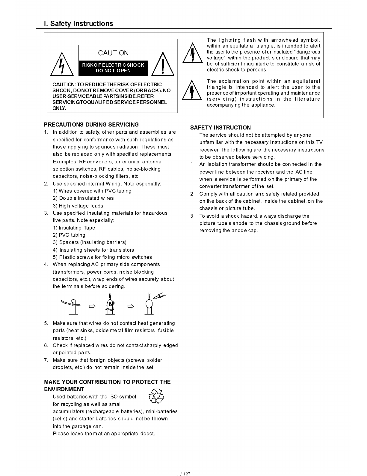
I. Safety Instructions
CAUTION: TO REDUCE THE RISK OF ELECTRIC
SHOCK, DO NOT REMOVE COVER (OR BACK). NO
USER-SERVICEABLE PARTSINSIDE. REFER
SERVICING TO QUALIFIED SERVICE PERSONNEL
ONLY.
The ligh tn in g flas h with a rrow hea d sym bo l,
A
within an e q uilateral triangle, is intended to alert
the user to the presence of uninsulated "dangerous
voltage” within the p roduct’ s enclosure that may
1 be of sufficient m a g nitude to constitute a risk of
electric shock to persons.
A
The e xcla ma tio n p o int within an e qu ilate r a l
tria ngle is in te nde d to ale rt the use r to the
presence of im portant operating and maintenance
. (s e rv ic in g ) in s tru c t io n s in th e lite ra tu re
accom panying the appliance.
PRECAUTIONS DURING SERVICING
1. In addition to safety, o ther parts and assemblies are
specified for conform ance with such regulation s as
those applying to s p u rio u s rad iation. These must
also be replaced only w ith specified replacements.
Exam ples: RF converters, tuner units, antenna
selection switches, RF cables, no ise-blocking
cap acitors, noise-blocking filters, etc.
2. Use specified internal W iring. Note especially:
1) Wires covered with PVC tubing
2) Double insulated wires
3) High voltage leads
3. Use specifie d insulating m aterials for hazardous
live parts. Note e specially:
1) Insulating Tape
2) PVC tubing
3) S pacers (insulating barriers)
4) Insulatin g sheets for transistors
5) P lastic screw s for fixing micro sw itches
4. When replacing A C prim ary side com ponents
(transformers, pow e r cords, noise blocking
cap acitors, etc.), w rap ends of wires secure ly about
the terminals before soldering .
Make sure that wire s do not contact heat generating
parts (heat sinks, oxide metal film resistors, fusible
resistors, etc.)
Check if replaced wires do not contact sharply edged
or pointed parts.
Make sure that foreign objects (screws, so lder
droplets, etc.) do not rem ain inside the set.
SAFETY INSTRUCTION
The service should not be attempted by anyone
unfa miliar w ith the nece ssary in stru ctions on this TV
receiver. The following are the necessary instruction s
to be observed before servicing.
1. An isolation transformer shou ld be connected in the
power li ne between the receiver and the AC line
when a service is perfo rmed on the primary of the
converter transform er of the set.
2. Com ply w ith all caution and safety related provided
on the back of the cab inet, inside the cabinet, on the
chass is or picture tube.
3. To avoid a shock hazard, always disch a rge the
picture tube's anode to the chassis ground before
rem oving the an ode cap.
MAKE YOUR CONTRIBUTION TO PROTECT THE
ENVIRONMENT
Used batteries with the ISO symbol
for recycling as w e ll as small
accu m ulators (rechargeable batteries), m ini-ba tteries
(cells) and sta rte r batteries should not be thrown
into the garbage can.
Please leave them at an a p p ropriate depot.
5
6
7
1/1 27
Page 4

4. C ompletely discharge the high potential voltage of the
picture tube before ha nd ling. The picture tube is a
vacuum and if broken, the glass will explode.
5. When repla cing a MAIN PCB in the cabinet, always
be certain that all protective are installed properly
such as control knobs, a d justm ent cove rs o r shields,
barriers, isolation resistor networks etc.
6. When servicing is required, observe the origin al lead
dressing. Extra precaution should be given to assure
correct lead dressing in the high volta g e area.
7. Keep wire s aw ay from high voltage or high tempera
ture components.
8. Before returning the set to the customer, always
perform an AC leaka g e current check on the exposed
m e tallic parts of the ca binet, such as antenn as,
terminals, screwheads, metal overlay, control shafts,
etc., to be sure the set is safe to opera te w itho u t
danger of electrical shock. Plug the AC line cord
directly to the AC outlet (do not use a line isolation
transformer during this check). Use an AC voltm eter
having 5K ohms volt sensitivity or more in the
following manner.
Conn e c t a 1.5K ohm 10 watt resistor p a ralleled by a
0.15|jF AC type capacitor, between a go o d earth
ground (water pipe, conductor etc.,) and the exposed
metallic parts, one at a tim e.
Measure the AC vo lta g e across the combinatio n of
the 1.5K ohm resistor and 0.15 uF capacitor. Reverse
the AC plug at the AC outlet and repeat the AC
voltage measurements fo r each exposed m etallic
part.
The m easured voltage must not exceed 0.3V RMS.
This corresponds to 0.5mA AC. A ny value exceeding
this limit constitutes a potential shock hazard and
must be correcte d im mediately.
The resistance measurement sho uld be done
between accessib le exposed metal parts and power
cord plug prongs with the power switch "ON". The
resistance should be more than 6M ohm s.
PRODUCT SAFETY NOTICE
Many electrical and m echanical parts in this TV
receiver have special safety-related characteristics.
These characteristics are offer passed unnoticed by
visual spection and the protection afforded by them
cann ot necessarily be obtained by using replacem ent
components rates for a highe r volta ge, wattage, etc.
The re p lacem ent parts which have these spe cial
safety characteristics are identified b y ^ marks on
the schem atic diagram and on the parts list.
Before rep lacing any of these com pon ents, read the
parts list in this m anual carefully. The use of
substitute repla cem ent parts which do not have the
same safe ty cha racteristics as spe cified in the parts
list may create shock, fire, X-RAY RADIATION or
other hazards.
AC VOLTMETER
Good earth gr ound
su c h as t he w a t er
pip e, co n d u c to r ,
etc.
1500 «hrra, 10vrt
Pla ce this probe
on e a c h e x-
pos e d me ta l lic
part
AC Leakage Current Check
2/ 127
Page 5

1. Do not power on.
1.1 Please check AC cable if connect to AC plug.
Is true the connector don’t connect to AC plug. Please connect it.
2.2 Please check AC cable if connect to AC power.
Is true the AC cable don’t connect to AC power. Please connect it.
3.3 Please check power board of fuse if broken.
If the F1 fuse is broken, Please pull out the AC cable from AC power. Please check AC L
power and AC N ground by multimeter, The read number is infinite, the fuse is broke. then
look up power board if not burn out place. Is true it. Please change power board or be changed
power board.
2. The power on switch of green extinguish.
2.1 The power of led(indicator light) is red light, To touch power on key when indicator light
wink.
Is true that the power DC output have somewhere short circuit.
Please check connector J39,J31 .If not connector direction is wrong.
Or the mainboard somewhere of power short circuit.
3/1 27
Page 6

3.The power is normal work ,but don’t backlight.
3.1 The indicator light work normal (green light ).
Please check Main board of transistor Ql&ollect if not has +5v voltage.
Is true Q18 collect hasn’t +5v ,To check Q18 if fail. Or to check Q18 of base if not low.
(Low is working, high don’t work*.
Please refer to attached sheet A circuit diagram.
3.2 Please check backlight of connector if not it direction is wrong or the connector of wire
compositor direction is wrong.
3.3 To check connector panel of voltage is +24v. It’s true .Then to check of the first pin if it
have +5V voltage, It’s true , than to check power board of +24v voltage ,It’s true. The panel
of backlight board is fail. The change panel of backlight board.
Please refer to attached sheet B Panel of datasheet.
4 .The screen don’t have picture But have backlight.
4.1 To check to panel of voltage ,To check main board of bead L69 and L57 connect if not
OK.Then check the L69 and L57 of voltage is +12v( 27 inch panel voltage is +5v, To check
L68 and L56 ). Next to check fuse F1 and connector J10 if not is +12v(27 inch panel voltage
is +5v). If isn’t please check power board of connector CON5 if has +12v( 27 inch panel
voltage is +5v).
4.2To check to main board +12 V voltage. To check to main board IC U35 of the first pin if
4/ 12 7
Page 7
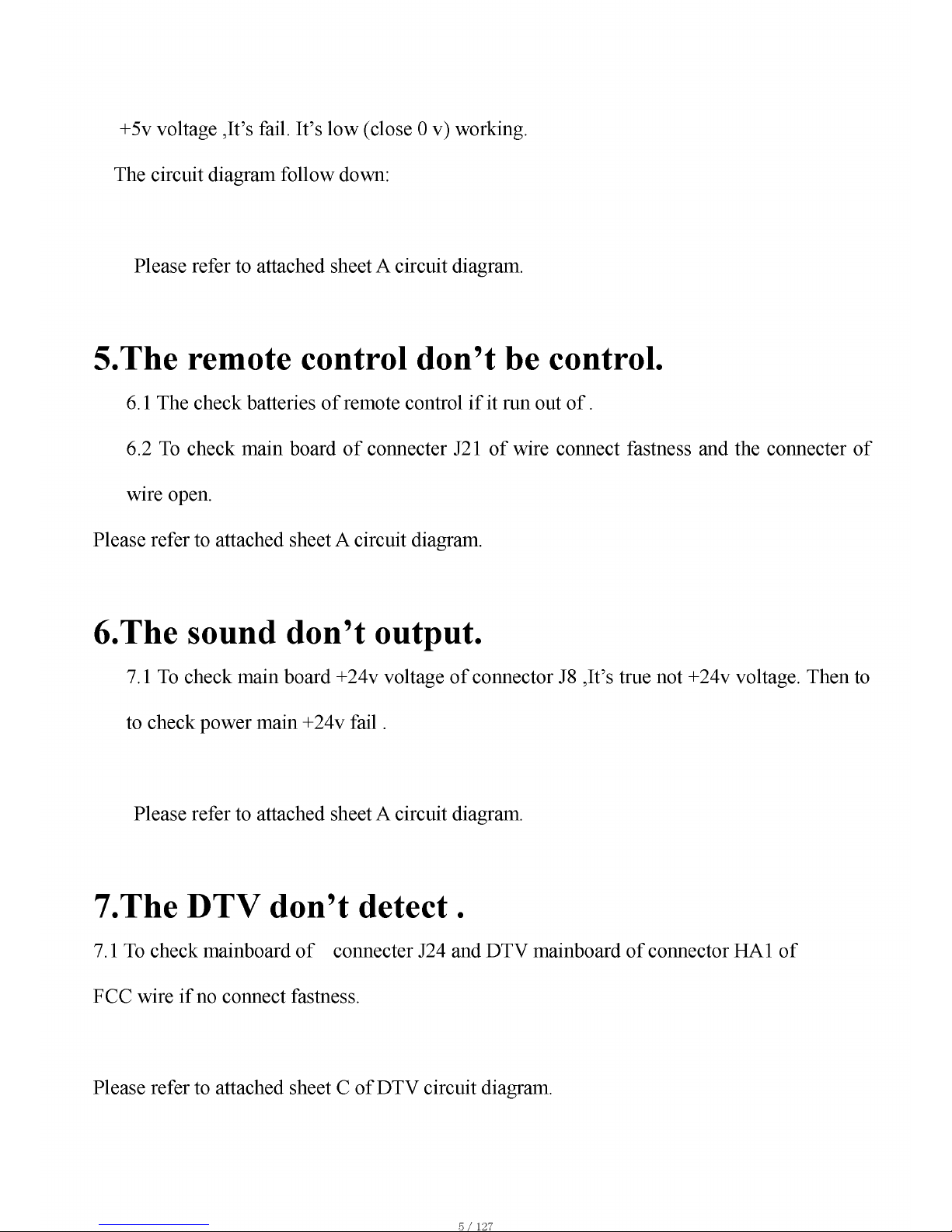
+5v voltage ,It’s fail. It’s low (close 0 v) working.
The circuit diagram follow down;
Please refer to attached sheet A circuit diagram.
5.The remote control don’t be control.
6.1 The check batteries of remote control if it run out o f.
6.2 To check main board of connecter J21 of wire connect fastness and the connecter of
wire open.
Please refer to attached sheet A circuit diagram.
6.The sound don’t output.
7.1 To check main board +24v voltage of connector J8 ,It’s true not +24v voltage. Then to
to check power main +24v fail.
Please refer to attached sheet A circuit diagram.
7.The DTV don’t detect.
7.1 To check mainboard of connecter J24 and DTV mainboard of connector HA1 of
FCC wire if no connect fastness.
Please refer to attached sheet C of DTV circuit diagram.
5/1 27
Page 8

Product Specification
Product Model: LCT37SHA
Screen Size: 37” diagonal
Screen Area: 819.6mm(H) x 460.8mm(V)
Aspect Ratio: 16:9
External Size: 925.8mm(W) x 708.0mm(H) x 240.0mm(D) (with Stand)
Gross Weight: 24 kg
Resolution: 1366 (H) x 768 (V) pixels (Each pixel has R/G/B 3 color cells)
Pixel Dot Pitch: 0.6mm(H) x 0.6mm(V)
Color: 16.7 millions of colors (R/G/B each 256 scales)
Gray Scale: 256 (R/G/B each 8-bit)
Peak Brightness: 500cd/m2
Contrast (Dark Room): 1000:1 (Typical)
TV System:
NTSC M, ATSC
Sound: Mono, Stereo, SAP (BTSC)
Sound Effect: Acoustic Cinema Enhancement
Power Supply: AC 120V, 60Hz
Power Consumption: 230W
Input/Output Terminal:
Antenna Input (F Type) x 2 (NTSC & ATSC)
RS-232 (D-Sub 9 Pin Type) x 1 (Only for DTV)
VGA (D-Sub 15 Pin Type) x 1
HDMI (Ver 1.1) connector x 1
Component Video - YPbPr x 2 (RCA Terminals)
Video Input (RCA Terminals) x 1
S-Video Input Mini Din 4 Pin Terminal x 1
Stereo, Audio x 5
1 set of Audio Output terminals (RCA, L&R)
SPDIF (Optical) x 1 (Only for ATSC)
Agent System: UL, cUL, FCC
NOTE:
• The specifications shown above may be changed without notice for quality
improvement.
6/1 27
Page 9

Support the Signal Mode
A. D-Sub Mode (VGA)
Resolution
Horizontal
Frequency
(kHz)
Vertical
Frequency
640 x 480
31.50 60.00
37.86 72.81
35.16 56.25
800 x 600 37.90 60.32
48.08 72.19
1024x 768 48.40 60.00
B. HDTV Mode (YPbPr)
Resolution
Horizontal
Frequency
(kHz)
Vertical
Frequency
(Hz)
480i 15.734 59.94
480p(720x480) 31.468 59.94
720p(1280x720) 45.00 60.00
1080i(1920x1080) 33.75 60.00
C. HDMI Mode
Horizontal Vertical
Resolution Frequency Frequency
(kHz)
(Hz)
480p 31.468 59.94
720p 45.00 60.00
1080i 33.75 60.00
- When the signal received by the Display exceeds the allowed range, a warning message shall
appear on the screen.
- You can confirm the input signal format from the on-screen.
7/1 27
Page 10

e
3
6
8
11
12
14
Standby
(riil
f CD
I ®
C D
C D
C D '
C D
._ Cs >
i C D <51
I _ / ETOw'' Sourca
\ C D J O <3e>
*D TV DOt
iQi R P ®
-• l VOL | mla | CH |l
| 0 !
©
H:
adt
-------
— « x y - Mar
22
24 ■
26
Fraaza \V-Chlp CCD ✓ Display
o o o o
S.Moda\FavorttB ¿ jj i / PICSlM
ob a o
P.Mod* \ Racall S laop / System
■oboo-
^ Bad Groan Yallw« iluas,
iQOOOj
-2
-4
-5
-7
-9
-10
-13
-15
-23
-25
Remote Control
EPower ( 0 ): Press to turn on andoff.
2Mute ( i* ): Press to mute the sound.
Press again or press VOL+/- to restore the sound.
30 ~9 Number Buttons: In TV mode,
press 0~9 to select a channel;
the channel changes after 2 seconds.
HEPG: Press to display EPG
(Electronic Program Guide) menu.
5S ource ( -g ): Press to select thesignal sources.
6DTV: Press to select Digital TV mode.
7D ot: Press number buttons with it
to select the channels directly in DTV.
81VOL +/-: Press to adjust the volume.
9C H +/-: Press to changes channels.
10 MTS: Press to repeatedly to cycle
through the Multi-channel TV sound
(MTS) options. Such as Stereo, Mono,
or Separate Audio Program (SAP broadcast).
1 1 < A ,T > , Enter: Press < A , T >
to move the on-screen cursor. To
select an item, press Enter to confirm.
12Exit: Press to return or exit the OSD menu.
13Menu: Press to display the OSD menu.
14V-Chip: Press to select the child protect mode.
15CCD: Press to select the Closed Caption mode.
16Freeze: Press to freeze the picture, press again to restore the picture.
(This button is not available forVGA mode.)
17Display: Press to display the channel information and it disappear after 3 seconds.
18Favorite: Press repeatedly to cyclethrough the favorite channel list.
19Add/Erase: Press to add or delete favorite channel.
20S.Mode: Adjust the TV sound by selecting one of the preset factory
settings, such as Normal, News, Cinema, Concert, or User.
21PIC.Size: Press to change the screen size, such as Full, 4:3, Panoramic. (Note: In VGA mode, it
can select picture size is Full. While in DTV mode, it can select picture size is: Full and 4:3. )
22Recall: Press to return to previous channel.
23Sleep: Press to sleep a time for the TV to turn off automatically, such as
15Min, 30Min, 60Min, 90Min, 120Min and, OFF. To cancel sleep time, press
Sleep repeatedly until sleep OFF appears.
24P.Mode: Adjust the TV picture by selecting one of the preset factory settings,
such as Hi-Bright, User, Cinema, Normal and Vivid.
25System: Press repeatedly to cycle through the system options: AUTO,
NTSC3.58 and PAL.(This button is activate for AV, S-Video input source.)
26Color Buttons:
Red: Press this button to access the red item or page.
Blue: Press this button to access the blue item or page.
Green: Press this button to access the green item or page.
Yellow: Press this button to access the yellow item or page.
8/ 12 7
Page 11

Optical
Output
TD 1336
Digital T uner
Flash
32mb
MT5351
MPEG D ec od er
DTV BOARD
PO W ER BOARD
<-
5V
<-
Stand by 5V
< -
12V
<-
9V
<-
24VA (For Class D)
24V (For LCD Panel)
Ana log
Tun e r
MT8293
HDMI R ecei ver
74L VC 24 5A X4
24 bit RGB Switch
MAIN BOARD
9/1 27
Page 12

MT8202E (PBGA388) LCDTV BOARD 4 LAYERS FOR A KAI
1. INDEX / POWER / RESET / EEPROM
2. LDO
3. MT8202E PBGA388
4. MT8202 DECOUPLING
5. DDR MEMORY & FLASH
6. MT5351 INTERFACE
7. HDMI MT8293
8. DAUGHTER BOARD IN
9. WM8776 & VIDEO BYPASS
10. AUDIO / VIDEO IN CIRCUIT
11 . V GA & PC AUDIO IN
12. LVDS OUT
13. BACK LIGHT / KEYPAD
14. TUNER IN
15. A V IN
16. AUDIO IN
17.AUDIO Amplifier
! :
’ - '
-
9VV FB42^-. , FB/NC 9V
9VV FB43~-.. FB/NC 9V
LVDSVDD
-----
LVDSGND 2,3
SCL
-----
SCL
9,1
SDA
-----
SDA
9,1
URST#
-----
URST# 3
8202UP3 1
-----
»8202UP3 1 3
GPIO2
-----
GPIO2 3,12
GPIO4
-----
GPIO4 3
GPIO14
-----
GPIO14 3,13
GPIO19
-----
GPIO19 3,13
9V
-----
9V 7,9
12V
-----
12V 12,1
RELAY ON
-----
RELAY ON 12
VS ON
-----
VS_ON 12
10/1 2
KAWA C o nfid ential
IN DE X / P OW ER / RE SE T / EE PR OM
Size Document Number
C AKAI MT820 2 27 US L VDS V0.0 ^ , „
C
_______—_______—_____—_____
— Checked:
ate: Thursday, April 13, 2006
_________
Page 13

Page 14

AVDD_VAD1
-)->AUDIO_GND
AADCVSS
-»LVDS_GND
-»VFE_GND
-»VFE_GND1
->>AVDD_VAD1
— XTALVDD
AVDD_VFE0
->>AVDD_VFE0
— VPLLVDD2
OTESTP2
►>TESTP3
>>TESTN3
>>TESTP4
>>TESTN4
>>AVICM
»PWM2VREF
>>DACFS
»REFF
»REFN
4
4
4
4
TP80 A
4 TP12Ä
TP13 9
4
4
4 TP45 £
4 TP46 $
4
4 TP47$
4 TP31®
4
4
4
4
4 TP8 A
TP9 A
4 TP10g
4
PWM2VREF C18
DACVDDA C16
LVDS GND C17
VPLLVDD1 D15
LVDS GND ri14
50 00 0c°00 00 0£ - - 00 000 00 £
FLLVDD1
PLLVSS2
PLLVDD2
PLLVSS3
PLLVDD3
XTALVDD
XTALC
XTAL
XTALVSS
ADCVSS
ADIN4/GPIO
ADIN3/GFIC
ADIN2/GFIC
ADIN1/GFIC
ADIN0/GFIC
ADCVDD
PWM2VREF
SVM
B
DACVSSA
G
DACVDDA
DACVSSB
DACVDDB
VFLLVDD1
VPLLVSS
VPLLVDD2
LVDDA
CK2P
CK2N
LVSSA
A0P
A0N
LVSSC
DVDD18A
GPIC
DVDD33A
UP3_5
UP3_1
UP3_0
VSYNCC
HSYNCC
GPIC
GPIC
IOOE#
IOCS#
IOA1
DVDD18A
A16
HIGHA7
HIGHA
6
HIGHA5
NC BALL
NC BALL
NC BALL
NC BALL
NC BALL
NC BALL
NC BALL
NC BALL
NC BALL
J24
K24
MT82 02
SOC K E T
VI0
DE_DVI
HSYNC_DVI
VSYNC_DVI
CEN_DVI/GPIO
DE_SOG/GPIO
OUT_27MHZ/GFIO
GPIO/PWM1
GPIO/PWM0
DVDD33
DQ31
DQ3C
DQ2£
DVDD25OPT
DQ2E
DQ27
DVSS25
DQ26
DQ25
DQ24
DQS3
DVDD25OPT
DQM1
DVSS1E
DQS2
DQ23
DQ22
DVSS25
DQ21
DQ20
DVDD1E
DQ19
DVDD25OPT
i Q QQQo Q i QQQQoQQQ§
DVDD25_CLK
RCLK
RCLKB
DVSS25
DVDD1E
BA0
RCS#
RAS#
DVSS25
CAS#
RWE#
DQ15
DQ14
DQ13
DVDD25
DGND/BALL
DGND/BALL
DGND/BALL
DGND/BALL
L DGND/BALL
LL DGND/BALL
B/A DGND/BALL
D/ DGND/BALL
GN DGND/BALL
SB33A
SB33A 9
DV33A
DV33A 9
| NC
CB135
AF25
AD24
AE24
AF24
AD23
AE23
AD22
AE22
AF22
AC21
AD21
AE21
AE19
AF21
AD20
AC22
AE20
AF20
AC19
AD19
AE17
AF17
AC16
AC15
AD16
AE16
AF16
AE15
AD14
AF15
AD15
AE14
AF14
AF13
AE13
AF12
AC14
AE12
AD12
AC12
GND
GND
GND
GND
GND
GND
8202UP3 5 R49
VGASOG
VGAHSYNC#
VGAVSYNC#
»VGASOG
sSvgahsyn c#
»VGAVSYNC#
A DOSm,,^
>A_DQS[0..3j
>A_RA[0..11j
>A_BA[0..1]
)A_DQM[0..1]
SA_DQ[0..31j
A_CLK
A_CLK#
A_CKE
A_CS#
A_RAS#
A_CAS#
A_WE#
»ADC_IN0
►>8202UP3_0
>>8202UP3_1
>>PWM0
>>PWM1
»GPI00
&GPIO1
»Sgpio;
>>GPIO3
>>GPIO4
&GPI07
►>GPIOE
>>GPIO£
»GPIOK
>>GPI011
►>GPI012
►>GPI013
>>GPI014
>>GPI015
»>GPI01E
&GPI017
»GPI01E
>>GPI01£
>>VCLK
>>CCIR_VCLK
►>CCIR_V7
►>CCIR_V6
>>CCIR_V5
>>CCIR V4
>SCCIR_V[0..3j
►> SCL0
►>SDA0
>>ADC IN4
>>TXDr
>SRXD'
>>TXC
>RXC
AOMCLK
AOBCLK
Caolrck
&ADIN
►A0SDATA1
&A0SDATA2
>>AR
&MPX1
►>MPX2
>>FCLK
>>FCMC
>>FDAT
0SCL_820;
►>SDA_820;
KAWA C onfid en tial
Title
MT8202E PBGA388
Size
C
Document Number
AK AI_M T820 2_27U S_LV DS_ V0.0
<Designer>
Checked: <Checker>
Rev
Date: Thursday Aoril 20 2006 Sheet 3 17
12/1 2
SB33B
»PLLVDD1
PLLVDD2
»PLLVDD2
PLLVDD3
PLLVDD3
XTALVDD
VPLLVDD1
»VPLLVDD1
DACVDDA
»DACVDDA
DACVDDB
»DACVDDB
DACVDDC
DACVDDC
SB33B
AADCVDD
»AADCVDC
ADACVDD
»ADACVDC
ADCVDD
»ADCVDC
VPLLVDD2
LVDDA
»LVDDA
LVDDB
»LVDDB
LVDDC
»LVDDC
DV25A
SB33B
SB33B
CE R351
SB33B
SB33B 9
GND
SB33B SB33B
Page 15

— XTALVDD
AVDD VAD1
—»AVDD_VFE1
— DACVDDA
AUDIO GND
AADCVSS
AUDIO_GND
LVDS_GND
VFE_GND
AADCVSS
VFE_GND1
STANDBY ANALOG POWER
ASB18A
T
T _
ASB33A
+ CE26
__ 1 ni 1F/1 nv —1—
J
10uF/10V
LVDS GND
T
T _
NORMAL VIDEO DAC POWER
DACVDD
BEAD/SMD/0603
T
r.
BEAD/SMD/0603
r.
BEAD/SMD/0603
r.
NORMAL VIDEO DAC POWER
AV33A
r.
+ CE33
1 ni iF/1 nv —'—
J
L/IND/DIP/P10.0
10uF/10V
AADCVSS
_l+. 1
T _
ADCV33A
+ CE35
10uF/10V —
L15 150uH
L/IND/DIP/P10.0
AUDIO GND
r
T _
T
x
T
x
T
x
FB10 fy - , FB
BEAD/SMD/0603
C20
LVDS GND
_
- K V -
r 47uF 1
LVDDA
CB40
= 0.1uF
LVDS GND
LVDDB
.
- ? 73f -
r 47uF 1
CB42
= 0.1uF
LVDS GND
LVDDC
_
- î 275f -
CB45
x
T
x
T
x
NORMAL AUDIO ADC / DAC POWER
ADCV33A
NORMAL ANALOG POWER
ASB18A
AV33A
1+ CE29 I
„-p . 10uF/10V ^
I LVDS GND I
T
NORMAL VIDEO ADC POWER
ADCV33A
________
FB9 FB
I C19
4.7uF
FB11 rr - \ FB
r
" L
ADCV18A
r
I
i C
"T" 1°L
C0
ND
CB25
0.1uF I 10uF/10v
C0805/SMD
AUDIO_GND
r
T _
T
0.1uF
C060
LVD:
T
x
I
X
AVDD_VFE0
T
x
_ œ L3s ^ FB
I C49
H ^ 10uF/10v ~*_
I C0805/Sf
1
J
MT8202 DIGITAL POWER & DECOUPLING
KAWA C onfid en tial
13/1 2
Title
MT8202 DECOUPLING
Size
C
Document Number
AK AI_M T820 2_27U S_LV DS_ V0.0
<Designer>
Checked: <Checker>
Rev
Date: Thursday/ Aûril 13 2006 Sheet 4 17
XTALVDD
XTALVDD
ADCVDD
»ADCVDD
AVICM
»AVICM
PWM2VREF
»PWM2VREF
DACFS
»DACFS
LVDDA
»LVDDA
LVDDB
»LVDDE
ADCVDD
LVDDC
»LVDDC
REFP
AADCVDD
»AADCVDD
ADACVDD
»ADACVDD
REFN
VPLLVDD1
»VPLLVDD1
VPLLVDD2
»VPLLVDD2
DACVDDA
PLLVDD1
PLLVDD2 TESTP3
» pllvdd;
PLLVDD3 DACVDDB
»PLLVDD3
VPLLVDD2 TESTN3
DACVDDA
TESTP4 VPLLVDD1
DACVDDB
»DACVDDB
DACVDDC TESTN4 VPLLVDD1
»DACVDDC
DACVDDC
AADCVSS
SB33A
AADCVSS
AVICM
AADCVDD
AADCVSS
AADCVSS PWM2VREF
ADACVDD
DACFS
Page 16

Page 17

HD0ii231n » vi [0..23]
HDMICEN
--------
HDMICEN
,+ CE61C
100uF/16v
>>HDMIHSYNC
»HDMIVSYNC
>Sde_sog
>>INT0#
>>CCIR_V1
>>CCIR_V3
>>SCL_8202
>>SDA_8202
»27MHZ
>>HDMIMCLK
»HDMIBCLK
&HDMILRCK
>>HDMISD0
>>HDMISD1
&HDMISD2
>>HDMISD3
HDMI_PLUGPWR
C632
0.1uF_
VCC
WP
SCL
SDA
EEPROM 24C04/C0DE
9993 SDA R700
9993 SCL R701
CRYS/49US/P4.8I
H th
hdmi_plugpwr
CE609
1+ | CB210
| 10uF/16v | 0.1l
CE613
1+ | CB212
10uF/16v | 0.1l
+CE611
47uF/16v
U48 AZ11 17-1 .8
S0T223/SMD
+ CE612
47uF/16v
DV33B DV33B DV33B
CE614
1+ | CB213
10uF/16v | 0.1u
CB218
0.1uF
o;
V J . NC
— NC
1C VCC
NC WP
NC SCL
GND SDA
EEPROM 24C04/C0DE
CB217
0.1uF
qoooo--oc
GPI02
GPI01
GPI00
CVCC18
CGND18
CI2CA
CSDA
CSCL
DSDA
DSCL
pWR5V
CVCC18
PGND
PVCC
EXT_RES
AVCC
RXC-
RXC+
AGND
AVCC
RX0-
RX0+
AGND
AVCC
RX1-
MT8293
I0VCC33
ODCK
I0GND33
QE10
QE11
I0VCC33
I0GND33
QE12
QE13
QE14
QE15
QE16
QE17
(ii ^O O OO C
LQFP128/SMD/8293
R707
— —
CB234 | Ci
CB234 _ L C633 FE
0.1uF j 0.01uF
15/1 2
RN27 33x4
-----2
RN29 33x4
-----2
RN30 33x4
RN31 33x4
I CB219 , C617 | CB220 | C618 | CB221 | C619 | CB222 | Ci
| 0.1uF | 1000PF | 0.1uF | 1000PF | 0.1uF | 1000PF | 0.1uF j
I CB224 | C622 | CB225 | C623 | C621 | C
| 0.1uF ~J~1000PF | 0.1uF | 1000PF | 1000PF ^ 0
CB223
000PF
0.1uF
T 01uFl
1000PF
CB227
- 01uF 1000PF
CB228
- 01uF
Ci2i
^ 1000PF=
CB229
- 01uF
I CB230
T 01uFl
C628 =
1000PF
_
CB231
01uF =
_
C629
1000PF
_
CB232
01uF =
C630
= =
_
CB233 |
0 1uF ^
Ci27
000PF
Ci31
000PF
CB214
0.1uF
I C614 | CB215 | C615 | CB216 |
| 1000PF | 0.1uF | 1000PF | 0.1uF j 11
C616
000PF
Ri9i
4.7K/NC
R789 Ci82
\ II CVBS OUT
100
R790
100
II
0.1uF
C683
33pF
=. ADD HDMI COAXOUT
HDMI C0AX0UT.C127 CHANGE 0 RESWHEN US
KAWA C onfid en tial
Title
HDMI INPUT MT8293
Size
C
Document Number
AK AI_M T820 2_27U S_LV DS_ V0.0
<Designer>
Checked: <Checker>
Rev
Date: Thursday/ April 20 2006 Sheet 6 17
AVCC
DV33B DV33B
AVCC
N o OUI
C
OVCP
PVCP
VCC
REGVCP
27MHZ
DV33B
HDMIRST#
PI2CA
OVCC
OVCC
PVCP
OVCC
XTL XTLO
AVCC I0VCC
OVCC
CI2CA
INT0#
DV33B
Page 18

HD MIV SY NC
^H DM IM CL K
>H DM IBC LK
>H DM ILR CK
>H DM ISD 0
^H DM ID E
>H DM IOD CK
^H DM IHS YN C
>H DM IVS YN C
—» VI^ .,2 3]
>>TXD
>>RXD
>>TXD1
>>RXD1
>>SCL1
OS DA 1
>>G PIO3
>>C CIR _V6
& SCL 0
»S D A 0
>>9V
3.6
3.6
3.11
3.11
3
3
1,9, 14
SB33B
Q
SB33B
SB33B
SB33B
R358
10k
R36 0 4
1°k /NC
R35 9 «
10k <
2N3 904
SO T23 /SM D
R361 .
10k /NC
R36 3
1
RE QU EST #
LR CK R222 . . . 0/NC
DA TA °R 23 °X > ^ ^ °/N C
------------
W '
------
DTV POWER CONTROL
CB 204
^ u F/ NC ;
CB 2°5
°.1 uF/ NC
LO = > DTV BOARD POWER OFF
HI = > DTV BOARD POWER ON
IRF 7316
SO p8/ SMD
9V VCC
L _L
SB33B
R64 0 > R 641 > R71 3 ?
22k /NC > 22k/N C> 22 k/NC > 22
R642
10k
0/N C
C601
1uF /NC
Q31
2N 3904
SO T23 /SM D/N
C60 2
1uF /NC
R7 8^ 0/NC
R78 7^ ^ S0/N C
Trace width of 12V>30mil
Trace width of 5V >40mil
1
n = n
V9 V
1 2
3
GND
1 4
T 5
V5 V
6
T 7
L = J
T X D : M T 5 3 5 1 T ra n s m it
R X D :M T 5 3 5 1 R e c e iv e r
T X D 1: M T 53 5 1& M T 8 2 0 5 C om m u n ic a t io n
R X d 1 : M T 5 3 51 & M T 8 2 0 5 C o m m un i c a tio n
RXD
— RX D1-
____
6X D * _
18
HD MIB CL K 17
16
15
VC C
GND
A7
A6
A5
A4
A3
A2
A1
U3 0 74L VC 245A
VI5
17
VI6
16
VI7
15
VI8
14
VI9
13
VI1 0
12
VI11
11
OE
DIR
B7
B6
B5
B4
B3
B2
B1
B0
VC C
GND
A7
A6
A5
A4
A3
A2
A1
A0
U31 74L VC 245A
VI1 3
17
VI1 4
16
VI1 5
15
VI1 6
14
VI1 7
13
VI1 8
12
VI1 9
11
OE
DIR
B7
B6
B5
B4
B3
B2
B1
B0
VC C
GND
A7
A6
A5
A4
A3
A2
A1
A0
U3 2 74L VC 245A
VI21
17
VI2 2
16
VI2 3
15
HD MIH SY NC
HD MIV SYN C
13
HD MID E
12
HD MIO DC K
11
OE
DIR
VC C
GND
A7
A6
A5
A4
U3 3 74L VC 245 A
49
FOR MT5351 INTERFACE
KAWA Confidential
Title
MT5351 INTERFACE
Size
B
Do cum en t Nu mb er
AKAI_MT8202_27US_LVDS_V0.0
<De sign er>
Ch eck ed: <C hec ker>
Rev
1
Date : T hurs da y, A pri l 1 3, 2 006 Sh eet 7 17
SB Sß B
HD MIM CL K
HD MIB CLK
HD MIL RC K
HD MIS D0
HD MID E ch ang e 2 /16
D D
HD MIO DC K
HD MIH SYN C
DV 33 B
n
20
HD MIM CL K
TXD LRC K
RXD HD MIS D0 DATA 0
TXD1 VI0
RXD1 VI1
VI2
VI3
5
SDA1
SCL1
RE ADY #
C
20
VC C
V5 V
V9 V 9V
VC C V5V
40
B
9V V9 V
RE QUE ST#
GP IO3
A
16/12 7
Page 19

INPUT
ADC_IN0
CCIR_V0
CCIR_V5
CCIR_V7
GPIO11
GPIO15
GPIO16
GPIO17
GPIO18
VFE_GND
AADCVSS
SY_R
SY_L
Y2_INB
Y2_GNDB
CB2_INB
CB2_GNDB
CR2_INB
CR2_GNDB
Y3_INB
Y3_GNDB
CB3_INB
CB3_GNDB
CR3_INB
CR3_GNDB
9V
OUTPUT
YQ
CBC
CRC
YQ_GND
CBQ_GND
CRQ_GND
SE33E VCC
CCIR V5 1 R724. CCIR V0 1 R726^
. 10K 1 y - " ;
GD!O for USB CONTOR
DIP6/W/H/P2.54
DVD POWER CONTROL
KAWA Co nfid en tial
17/ 12
SWV9
VCC DV33B
SWV9 SWV9
SB33B SB33B
SW1S2
0K 1
SB33B
Page 20

INPUT
GPIO7
>>SCL
>>SDA
>>SDA_8202
>>SCL_8202
(SAOSDATA1
&AOMCLK
><AOBCLK
>SAOLRCK
>>ADIN
>>YPBPR1_L
>>YPBPR1_R
>>YPBPR2_R
>>YPBPR2_L
>>YPBPR3_R
>>YPBPR3 L
>>VGAR_IN
>SVGAL_IN
►Stestp;
>>AR
OUTPUT
AUSPR
DV33B SB33B
COD_VOUTR
COD_VOUTL
REMARKS: * FOR LCDTV
LCDTV
R226 R232 CB132 R233 CB133 R227 CB131 R234 CB134 R666 C134 C152 CE139 Q27 CE140 CE138
22 22
F
ft
id
m
2
2
56pF 22 56pF 22
F
p
6
5
24K NC NC NC NC NC NC
BYPASS VIDEO OUTPUT
AUDIO BYPASS MUTE
SB33B
BYPASS AUDIO OUTPUT
R648 10K R649 5.1
----
—
X
X
^ U4i
£ > n
U46A
1
/S A0/NC
NJM4558 OPA
OPA1V9
L J
R652 C
-----
—
R653 10K
W
---
C100UF16V/D6H11
R654 5.1
----
—
X
X
^ U4i
£ > n
U46E
7
NJM4558 OPA
OPA1V9
KAWA C onfid en tial
L J
Title
M8776 & VIDEO BYPASS
Size
C
Document Number
AK AI_M T820 2_27U S_LV DS_ V0.0
<Designer>
Checked: <Checker>
Rev
Date:
Saturday Aoril 22 2006
Sheet y
18/1 2
SCL
AUSPR
AUSPL
IESIP2 AVCVBSO
VCC 9V VCC
VCC
AL
OP1VREF
Page 21

Page 22

VGAVSYNC#
RED+ 3
RED- 3
GREEN+ 3
GREEN- 3
BLUE+ 3
BLUE- 3
VGASOG 3
VGAHSYNC# 3
VGAVSYNC# 3
TXD 3,7
VGAR_IN
VGAL_IN
■ VFE_GND
DIODE SMD BAV9E
VGA IN
NEARLY VGA CON
VGA_PLUGPWR
VGA PLUGPWR
NC VCC
NC SCL
GND SDA
EEPROM 24C02
NEARLY 8202
R267 1.5K
RCA1X2 AV2-8.4-13P
^ 1
_________
VGAR IN
^ 2
________
VGAL IN
^ chan ge
VGA/DVI AUDIO INPUT
KAWA C onfid en tial
Title
VGA IN & PC AUDIO IN
Size
Document Number
<Designer>
Rev
C
Checked: <Checker>
1
20/ 12
VCC
Page 23

Page 24

IR
>> IR 3,15
GP IOI O
— GP IO10 3
GP IO1 2
— GP IO12 3
GP IO1 3
— GP IO13 3
GP IO1 4
— GP IO14
1,3
PWMO
— PWM O 3
PWM 1
— PWM 1 3
82 02U P3 0
—>>8 20 2U P3 _0 3
GP IO1 4
— GP IO14
1,3
GP IO1 9
— GP IO19
1,3
VC LK
— VCL K 3
F A21
—»F _ A 21 3
CC IR V 2
—>>C C IR_ V2 3
12V
» 1 2 V
1,12
C3 5 11100 0pF TV/ AV 2
C36 10 00pF ME NU 3
C3 7 100 0pF VO L- 4
C3 8 100 0pF
VO L+ 5
C39 1 000 pF C H- 6
C10 6 10 00pF CH + 7
C101 100 0pF IRR 8
C99 10 00pF L ED RED 9
C53
10 00p FED GRE 10
C12 4 10 00pF 82 02 UP 3 0 11
C52 1000 pF POW 12
13x1
DIP 13/ P2.0
ADC KEY & GPIO KEY KEYPAD
KAWA Confidential
Title
BACK LIGHT / KEYPAD
Size
B
Do cum en t Nu mb er
AKA I_MT8202_27US_LVDS_V0.0
Ch eck ed
<De sign er>
<Ch ecke r>
Rev
1
Date : T hurs da y, A pri l 1 3, 2 006 Sh eet 13 17
SB 33B
D D
C
B
A
22/1 27
Page 25

SCL
1,9
• SDA
1,9
•CV BS 0 10
•TV GND 10
AF 10
SIF 10
• AD C IN 4 3
9V 1,7,9
T
TUNER SIF1NTSC 4.5MHz BPF
CE6 26 _ J f 33 uF/1 6V AF
R178
R/NC
R179
R/NC
C191
20pF
R41 8 0
----
C649
820p F
560pF
CB24 2
0.1uF
L93 2.2uH
_ /Y Y Y >
________
- T U C VBS R31 7. ^ 18
L/IN D/SM D/080 5
C656
330p F
C657
330p F
CB24 3
0.1u F
R58^
FQ1216 : PAL
FQ1236 : NTSC
Title
<Title >
Size
Cust
Doc umen t Num ber
>m<Doc>
Rev
<Rev
Date: Thu rsday, Apr il 13, 200 6 Sheet o f 1
ADDRESS
TUNER IF
C0 84
KAWA Confidential
Title
TUNER IN
Size
Cus t
Docu ment N umbe r
AKAI_MT8202_27US_LVDS_V0.0
<Des igner>
Che cked: <Ch ecker>
Rev
1
Date: Thu rsday , Ap ril 13, 20 06 Shee t 14 17
SCL
AF
SIF
D
C
VCC
9V
SWV 9
A
23/1 27
Page 26

Page 27

»A OS DA TA 2
NA OM CL K
NA OB CLK
»A OL RC K
>MU
SP OUT R
AU SPR
AU SP L
OP OU TR
OP OU TL
A_ MU TE
3,9
9
15
17
17
9,1 7
U55
33
33
SD AT A A OU TL
DE M# /SC LK V A
LR CK A GND
MC LK AOUT R
CS 433 4 2 -C H A UD IO DAC
SO P8/ SMD
CE9 7
10u F/25 V
FB 38 FB
CE 169
10u F/2 5V
\ 7
C65 9
1uF
CB 244
0.1 uF
\ 7
R17 5 20 K
OP 1VR EF
o
CE 98
10u F/25 v
CB 246
0.1 uF
GPIO DECRIPTION
UP3_4 : SW SCL
UP3_5 : SW SDA
ERO0/UP3_0 :KEYPAD POWER
ERO1/UP3_1 : MAIN POWER SWITCH
VCLK : KEPAD CH+
GPIO19 : KEPAD CH-
DE/GPIO : DVD IR
CCIR_CLK : PDP USE
CCIR_V4 : PDP USE
GPIO0 : PDP USE
GPIO1 : NO USE
GPIO2 : LVDS POWER SW
GPIO3 : DTV POWER CONTROL
GPIO4 : EEPROM WRITE PROTECT
GPIO5/TXD : 2nd UART FOR MT5351
GPIO6/RXD : 2nd UART FOR MT5351
GPIO7 : AUDIO BYPASS MUTE CONTROL
GPIO8 : SPEAKER SWITCH
GPIO9 : AUDIO MUTE
GPIO10 : Indicates active video at HDMI port
GPIO11 : DVD POWER CONTROL
GPIO12 : AV SWITCH
GPIO13 : HDMI Hot Plug Detect
GPIO14 : NO USE
GPIO[15..18] : FOR DVD CONTROL
GPIO/PWMO : DIMMING
GPIO/PWM1 : BACKLIGHT ON/OFF
OUT_27Mhz/GPIO : HDMI CRYSTAL
SDA1 : TO MT5351 I/F REQUEST
SCL1 : TO MT5351 I/F READY
F_A21 : KEYPAD(LED RED)
ADCIN0 : KEYPAD
ADCIN3:PDP 5VD DETECT
ADCIN4:FOR TUNER AFC
CCIR_V[0-3] : KEYPAD
CCIR_V5 : AUDIO SWITCH
CCIR_V6 : RESET DTV
CCIR V7 : YPBPR VIDEO SWITCH
I 1
KAWA Confidential
Title
SUB WOOFER
Size
B
Do cum en t Nu mb er
AKAI_MT8202_27US_LVDS_V0.0
<De sign er>
Ch eck ed: <C hec ker>
Rev
1
Date : T hurs da y. A pri l 1 3, 2 006 Sh eet 16 17
AO SD ATA 2
AO MC LK
AO BC LK
AU SPR
AU SP L
VCC
O
D D
AO SD ATA 2 AU SP LL DAC VA
AO BC LK DA CVA
AUS P
4
C
B
A
25/1 27
Page 28

GPIO8: SPEAKER SWITCH(INTERNAL OR EXTERNAL
5x1 W/ HOU SIN G
DIP 5/W /H/ P2.5 4
R780 R187 R760 CB16 CB19 CE22
LCDTV
NC 51K 2.2K NC NC NC
J KAWA Confidential
Title
AUDIO Amplifier
Size
B
Do cum en t Nu mb er
AKA I_MT8202_27US_LVDS_V0.0
<De sign er>
Ch eck ed: <C hec ker>
Rev
1
Date : S atu rda y. A pri l 22 , 2 006 S hee t 17 17
D D
C
B
26/1 27
Page 29

MT5351RA-V2
MT5111 / MT5351 REFERENCE DESIGN - 4 LAYERS
Rev History P# DATE
RA-V1 INITIAL VERSION 2005/06/15
RA-V2
ADDED AUDIO SWITCH / REFINE POWER CIRCUIT
2005/07/14
BEAD/S MD/1206
l^ fb
.
DIRSIW IHIR2.54
+3.3V
x-r ».22 0üF/1 6v ^ ^ 0.1uF
C220 UF16V /D6H11 C06 03/SMD
,
+ CE2
x-r ».22 0uF/16v
C220 UF16V /D6H11
POWER INPUT FROM MAIN BOARD
01. INDEX AND INTERFACE
02. POWER
03. TUNER
04. MT5111 ASIC
05. MT5351 ASIC
06. MT5351 PERIPHERAL
07. DDR MEMORY
08. NOR FLASH / JTAG / UART
NS : NON-STUFF
NAME TYPE DEVICE
+12V POWER +12V POWER SUPPLY
+5V POWER +5V POWER SUPPLY
+5V tuner POWER +5V TUNER POWER
DV33_DM POWER +3V3 MT5111 POWER
DV1S POWER +1V8 MT5111 POWER
DV33 POWER +3V3 MT5351 POWER
AV33 POWER +3V3 MT5351 ANALOG POWER
DV25 POWER +2V5 MT5351 DDR POWER
DV12 POWER +1V2 MT5351 POWER
GND GROUND GROUND
D1
SOT23/SMD
. +5V
9 FB1
I
____
rv\
BEAD/S MD/0603 CB2
Z 0.1uF
C0603/SM D
SPDIF CIRCUIT
DIGITAL OUTPUT
-7 I - '
2 +12V
2,6 +5V
2,5,6,S DV33
I
2,3,4,5 ,6,7,S GND
4,5,S ORESET#
5 RE QUEST#
5 R EADY#
« » -
REQUE ST#
GLOBAL SIGNAL
« » -
t U0RX
t U0TX
t U2TX
t U2RX
UART (RS232)
VOR[ 0..7]
VOG[0 ..7]
VOB[0.. 7]
VOPCLK
VOH SYNC
VOVS YNC
VODE
DIGITAL VIDEO OUTPUT
5 AO1M CLK
5 AO1 LRCK
5 AO1B CK
5 AO1S DATA0
5 ASP DIF
AO1SDATA 0
« » -
DIGITAL AUDIO INTERFACE
5 AUD _CTRL
« » -
MediaTek Confidential
Title
IN D E X
Size
Cus
Docu ment Number
3m M T53 51 RA -V 2
T w in S o n C h a n
Rev
1
Date:
Monda y. Fe bruary 2 0. 2006
Sheet 1 of S
J1
L19
DV33
5 ASP DIF
AUD_C TRL
Page 30

28/1 27
Page 31

2, 4 +5 V_ TU NE R « » -
1. 2. 4.5 .6 .7 .8 G ND
« » -
GLOBAL SIGNAL
4 R F_A GC
4 IF AGC
4 2n d_ IF +
4 2n d_ IF -
4 TU N ER _S C LO
4 TU N ER _S D AO
TU N E R SC LO
TU N E R SD AO
TUNER INTERFACE
MediaTek Confidential
Title
TUNER
Siz e
Cu st
D ocu m en t Nu m be r
,m MT5351RA-V2
TwinSon Chan
R ev
1
Da te :
M on da v. F eb ru ar y 20 . 2 00 6
Sh ee t 3 of 8
A D
GN D
A
29/1 27
Page 32

CRYS/DIP/SMD
BEAD/SMD/0805
5 1+CE19
DVDD18 DVDD18
"4 ^
CB22 ^ = 0.1l
1 n 1 nF rnßr
■ H
CB22
:0.1uF
C0603/SMD
I C0603/SMD C0603/SMD C0603/SMD C0603/SMD C0603/SMD C0603/SMD
Dig ita l 1.8V By pas s C ap s
AVDD3
4 °
CB26
BEAD/SMD/0603 ^^ 0.1uF
I C0603/SMD
L _ D« 5
BEAD/SMD/0805 J[+ CE2C5 1 + CE
C
DVDD33 DVDI
- Î i
^ _ CB28
C10UF16V/D5H
CB28
:0.1uF
C0603/SMD
I C0603/SMD C0603/SMD C0603/SMD C0603/SMD C0603/SMD C0603/SMD
Dig ita l 3 .3V By pas s C ap s
CB27
BEAD/SMD/0603 ^ ^ 0.1uF
I C0603/SMD
L _ d M6 .
BEAD/SMD/08055 1 + CE
AVDD33 AVD
- î i
^ _ CB40 HJH
BEAD/SMD/0603
H
CB40
:0.1uF
C0603/SMD
CB35
C0603/SMD C0603/SMD C0603/SMD C0603/SMD C0603/SMD
An al og 3 .3V B yp ass C aps
BEAD/SMD/0603
J
CB
— 01
C0
ADVDD
i =.
= 0.1
C0603/SMD
ADVDD33_2
CB41
SIF LEVEL SHIFTER
1.2.3.5.6.7.8 GND
1.5.8 ORESET#
« » -
« » -
GL O BA L S IG NA L
3 RF_AGC
3 IF_AGC
3 2nd_IF+
3 2nd_IF-
3 TUNER_SCLO
3 TUNER_SDAO
TUNER SCLO
TUNER SDAO
TU NE R I NTE RF AC E
5 TS
5 TS
TS1ERROR
TUNER_SDA1
+5V_TUNER
ï _
DV3 _DM
> R29 .
> 10K '
R0603/SMD
R30
> 10K
R0603/SMD
R31
> 4.7K '
R0603/SMD
R32
> 4.7K
R0603/SMD
TUNER_SDA
TUNER_SCL1
1 * 1
-----
1 2N7002
J N-MOSFET
TUNER SCL
3 QF2 1
TUNER SDA1 TUNER SDAO
C0603/SMD
R0603/SMD
TUNER SCL1
_______Bid
______
TUNER SCLO I
M ediaT ek C onfid ential
R0603/SMD
Title
MT5 111 ASIC
Size
C
MT5351 RA-V2
TwinSon Chan
Rev
1
Date: Monday February 20 2006 Sheet 4 of 8
30/1 27
J^A rnz
TS IN PU T
FB4
Page 33

.
J Ü
TU,:Ï>D/D1,0
2î î sïïî
1.2.3.4.6.7.8 GNC
| | E Ü s i :# =
6 OPWM0 - UPWM0
----------
6 gXSÜO Q =
6 VCXÛ0 —VCX00
-----------
GLOBAL SIGNAL
8 H W ! f I e s s e e
‘ Psas ;? B d S S =
, FLASH INTERFACE
, AUDIO INTERFACE
i l H
I JTAG PORT
I ü
, UART (RS232)
ANALOG PART
I cï 1 c!ï I ci
03/SMD I C0603/SMD | C0
Media Tek Confidential
MT5351 ASIC
DDR
Add by Ada
31/1 27
Page 34

32/1 27
Page 35

22x4MEM WE#
MEM -DDR13
l7 RN22^
MEM_-DDR12
MEM_-DDR13
; 22x4MEM_RAS#
22 MEM ADDR; MEM -DDR3 R68
MEM ADDRII
MEM CLKEN
+1V25_DDR + 1V25_DDR
R«1^ I
—R«21 2 75X4
MEM -DDR12 R64 . . 75
MEM CAS# R66 .
I R^' C C
; R«2^
' RN27 2 75x4
MEM_-DDR11 R72 -
MEM_C LKEN R78 . . NS/75
,
1 RN33 2 75X4
CL OSE D TO MT5 351 CL OSE D T O D DR
RN 34 8
i R g C a n M i
___
MEM DQM0
___
DQ15
VSSQ
DQ14
DQ13
VDDC
DQ12
16 DDR TSOP-6
TSÛU_0D65_22D6LX9D7W_66S^
DDR#1
___
MEM CLKA#
MEM DQM2
MEM -DDR12
MEM ADDRII
MEM_-DDR1C
DQ15
VSSQ
DQ14
DQ13
VDDQ
DQ12
16 DDR TSOP-6
TSÛU_0D65_22D6LX9D7W_66S^
DDR #2
6 DV25
8 GNC
MEM CLKB#
MEM -DDR12
MEM ADDRII
_ GND
GL OB AL SIG NA L
RDQ[0..
RDQS[0
5 RDQ[0..3r
5 RDQS[0..3'
5 RDQM[0..3'
5 R A^.. ^]
5 RB—[0..1'
5 RCLK0
5 RCLK0#
5 RCS#
5 RRAS#
5 RCAS#
5 RWE#
5 RCKE
5 RCLK1
5 RCLK1#
6 MEM_VREF
-DD R-M EM ORY
__________________
EQUAL LIN E LENGTH
RCLK0 R1
CL OSE D T O MT5 351 CL OSE D T O D DR
RCLK0# R1
S05^
RCLK1 R1
RCLK1# R1
CLO SED T O M T53 51 C LOS ED TO DD R
-
+1V2
-f c
C142 I C143
■ Q.iui ■ Q.iui ■ 0.iui ■ 0.iui ■ 0.iui ■ 0.iui ■ p.iui ■ 0.1uF ■ 0.1 uF I 0.IÜT I 0.
C0603/SMD C0603/SMD C0603/SMC C0603/SMD C0603/SMC C0603/SMD C0603/SMD C0603/SMC C0603/SMC C0603/SMD C0603/SMD C0603/SMD
I CE
C170 ~ Z L C1
— -C1
_ C1
C147 “ T L C148 C150 _
T C161 T C162 T C163 t T l
—— 0 1uF —— 0 1uF —— 0 1uF —— 0
I C1
I
“ “ 0 . 1uF = 0 1uF ^ ^ 0 1uF ^ ^ 0 . 1uF ^ 0 1uF ^ ^ 0 . 1uF ^ ^ 0 1uF ^ ^ 0 1uF ^ ^ 0 . 1uF ^ ^ 0 1uF . 1uF ^ ^ 0 1uF
• 0603/SMD C0603/SMC C0603/SMC C0603/SMC C0603/SMD C0603/SMD C0603/SMC C0603/SMC C0603/SMC C0603/SMC C0603/SMD C0603/SMD
+1V25_DDR
CB133 C167
0.1uF ^ ^ 0.1uF
C0603/SMD C0603/SMD
BYPASS CAP. FOR TERMINATOR
(EVERY 2 RESISTOR PUT 1 BYPASS CAP.)
+CE25 C153 C154 C155 C156 C157 C158 C159 C172
C
220uF/16v “ 0.1uF “ 0.1uF “ 0.1uF “ 0.1uF “ 0.1uF “ 0.1uF “ 0.1uF “ 0.1uF —
• 220UF16V/D6H11 C0603/SMD C0603/SMC C0603/SMD C0603/SMC C0603/SMC C0603/SMD C0603/SMC C0603/SMD
DV25
Jb
<-T->22
I C2
DV25
i
T •
CE26 CB125 CB126 C173 C174 C175 C176 C177 C178
220uF/16v I ^ 0.1uF H ^0.1uF I ^ 0.1uF H ^0.1uF ^ ^ 0.1uF I ^ 0.1uF H^0 .1uF I ^ 0.1uF
C220UF16V/D6H11 I C0603/SMD C0603/SMD C0603/SMD C0603/SMr C0603/SMD C0603/SMD C0603/SMC C0603/SMD
BYPASS CAP. FOR DDR
CE24
!7uF/16v
C47UF16V/D5H5
BYPASS CAP. FOR DIMM
+1V25_DDR FOR DDR TERMINATOR
MEM VREF FOR DDR AND MT5351 VREF
C102 1 C105 1 C106 I C107 I C108 1 C109 1 C110 i C111 I C103 '
^ 0 . 1uF ^ 0 1uF ^ 0 1uF “ 0 . 1uF ^ 0 1uF ^ 0 . 1uF ^ 0.1uF ^ 0.1uF ^ 0.1uF C0
I C0603/SMD C0603/SMD C0603/SMC C0603/SMC C0603/SMD C0603/SMD C0603/SMC C0603/SMD C0603/SMD
+ CE29
-n220uF/16v
C220UF16V/D6H11
A DD b y A d a
M ed iaTek Confid en tial
Title
D D R M E M O R Y
Size
|Rev
Cust
,m MT5351RA-V2
Tw in So n Ch a n \ 1
Date:
Monday February/ 20 2006
Sheet 7 of 8
DV25 DV25 DV25 DV25
MEM_DQ15 MEM_DQ16
DV25
MEM_DQ10
R65
MEM DQS1 MEM_DQS3
MEM VREF MEM VREF
R71
MEM_CLKA
R0603/SMD
MEM_CLKA#
MEM_CLKB
R0603/SMD
MEM_CLKB#
+1V25_DDR
33/1 27
Page 36

34/1 27
Page 37

Basic Operations & Circuit Description
MODULE
There are 1 pcs panel and 5 pcs PCB including 3 pcs Extension PCB, 1 pcs Timming controller board and 1 pcs Back Light board
in the Module.
SET
There are 6 pcs PCBs including 1 pcs ATV Tuner board, 1 pcs keypad board, 1 pcs Remote Control Receiver board, 2 pcs L/R
Speakers and 1 pcs Main(Video)board, 1 pcs ATSC board in the SET.
35/1 27
Page 38

PCB funtion
1. Power :
(1). Input voltage: AC 120V, 60Hz.
(2). To provide power for PCBs.
2. Main board : To converter TV signals, S signals, AV signals, Y Pb/Cb Pr/Cr signals, DVI/HDMI signals and
D-SUB signals to digital ones and to transmit to Control board.
3. Control board : Dealing with the digital signal for output to panel.
4. Extension board : Output addressing signals.
5. ATV Tuner Board : To convert TV RF signal to video and SIF audio signal to Main board.
6. ATSC Board : Receiver and converter ATSC TV signal to transmit to main board.
36/1 27
Page 39

PCB failure analysis
1. CONTROL : a. Abnormal noise on screen. b. No picture.
2. MAIN : a. Lacking color, Bad color scale.
b. No voice. (Make sure status: Mute / Internal, External speaker)
c. No picture but with signals output, OSD and back l ight.
d. Abnormal noise on screen.
3. POWER : NO picture, no power output.
4. Back Light : a. No picture.
b. Flash on screen.
c. Darker picture with signals.
5. ATV Tuner : a. No ATV Noise
b. No ATV signals
6. ATSC: a No ATSC TV signal
37/1 27
Page 40

Main IC Specifications
- M13S128168A (ESMT)
2M x 16 Bit x 4 Banks Double Data Rate SDRAW
- MT5111CE
Single-Chip HDTV/CATV Demodulator
- MT5351
MT5351 is a DTV Backend Decoder SOC which support flexible transport demux,
HD MPEG-2 video decoder, MPEG1,2, MP3, AC3 audio decoder, HDTV encoder.
MT5351 is powered by ARM 926EJ with 16K I-Cache and 16K D-Cache. It can support
64Mb to 1Gb DDR DRAM devices with configurable 32/64 bit data bus interface.
- MT8202
MT8202G is a highly integrated Single-Chip for LCD TV supporting video input and output
format up to HDTV. It includes 3D comb filter TV decoder to retrieve the best image from
popular composite signals.
- MT8293
HDMI PanelLink Cinema Receiver
- R2S15102NP
Digital Power Amplifier R2S15102NP
- WM8776
24-bit, 192kHz Stereo CODEC with 5 Channel I/P Multiplexer
38/1 27
Page 41

MT5111CE
MT5111CE
Single-Chip HDTV/CATÿ Demodulator
Key F e a t u r e § r i r : ? - 1* ’
a Compliant with-ATSC digital television standard
H Supports SCTE DVS*031 and ITU J.83 Annex B digital CATV standard
Accepts direct IF (44 MHz or43.75MHz) and low IF (5.38MHz)
i Differential IjF input with programmable input signal level: 0.5Vpp to
NTSC interference rejection capability
Compensate echo up to -5 to +47us range for,terrestrial (fDfTVt
reception -g ll » ^ |:?
On-chip 10-bit ADC for HDTV/CATV demodulator
On-chip programmabife ggjn gmplifier § 11 | I
25MHz crystal for clock generation
On-chip PLL clock generation ’
Full-digital timing reipov.ery[ rjip VCXO is required I 41
Full-digital frequency offset recovery with wide acquisition range +1MHz
for ATSC and ±250kHz for CATV reception
Dual digital AGC dpntrols for iF and RF respectively
. I| ft
MPEG-2 transport stream output in parallel or serial format
Qh-chip error rate estimators for TS packets, TCM decoder, and
equalizer ,
EIA/CEA-909 antenna interface ,i .
Controlled by l2C interface
Supports sleep mode to save power consumption
Core power supply: 1,8V, peripheral power supply: 3.3V |
100-libFP package 1
-j
'
, i s
ll|ad|fre%
w
i MediaTek Inc. Confidential
39/ 127
Page 42

MT5111CE
Functional Block Diagram
AGC_RF +-
AGC_IF +-
General Description
MT5111CE is a fully integrated single-chip 8-VSB and 64/256-QAM
__ r if?
demodulator. The ehip is designed specifically for the digital terrestrial HDTV and
CATV receivers, and is fully compliant with ATSC A/53, SCTE.DVSÉ31, and ITU
J.83 Annex B standards. | .
MT5111CE includes a 10-bit A/D converter, 8-VSB/(pAM demodulator, TCM
(Trellis-Coded ^Modulation) decoder, and Reed-Solomon- Fdrward Error
Correction decoder Moreover, arr internal controller handles the acquisition and
tracking to ensure the best receiving; performance. The internal controller
communicates with the external host controller via the l2C-compatible interface,
and also provides direct control to the RF tuner via the second l2C-compatible
i y r
A MediaTek Inc. Confidential
40/ 127
Page 43

MT5111CE
_ July 20 0 i
interface.
MT5111CE accepts either the direct IF signals centered at 44MHz or ^
43.75MHz, or the low IF signals g^ratered at 5 38MKz The center frequency of *
the incoming IF signal can also be programmed to other frequencies for various-
applications. An On-chip progrjmmable gain-controlled amplifier is designed to
provide sufficient signal amplitffde when the received RF signal is weak. The IF
signal is first sampled by a 10-bit A/D converter. Afterward, the digitized samples
are further processed for adjacent channel interference rejection.
MT5111CE measures the power level of the digitize<isequenc§, and feeds
the control voltages back to the RF tuner and the1 IF amplifier respectivdly. The
control voltages are converted to analog signals through the on-chip 1-bit sigma
delta D/A converters plus the off-chip R-C low-pass filters. The automatic gain
control keeps:the received power level at a desired level and maximizes the
received SNR.
The carrier frequency offset and symbol timing offset are both estimated and
compensated by a fully digital synchronizer. The synchronizer also controls the
rate conversion in the digital re-sampling device by estimating the sampling
frequency offset. All synchronization in MT5111CE are integrated in digital circuits,
no external VCXO is required. i;
The equalizer is adopted, to cancel the effect of multi-path fading channel
during signal propagation, in the air or over cable networks The equalizer is not
only capabje c?f acquiring correct coefficients combination by specified adaptive
algorithms, but also programmable to different configurations for various channel
conditions. ,
The following FEC decoder corrects most of the errors by the concatenation
- p 3----------------------------------------------------------------------------------------------------------------------—
----------------------------------- .
A i MediaTek Inc. Confidential
Page 44

MT5111CE
July
of TCM and Reed-Solomon decoders. For CATV reception, MT5111CE detects
and aligns de-puncturing timing of the received sequence. The timing
synchronization is also automatically performed to lock the FEC frames. The on*
chip error rate estimator can simultaneously monitor the receiving qualities at the
three stages: equalizer* output, JfCM decoder, and transport stream packets. The
chip finally outputs! the decodef MPEG-2 packets in either the serial or parallel
transport stream format. §
In addition to the demodul||pri of HDTV signal, MT5111CE also provides the
capability to remove the NTSC co-channel interference. To achieve’the best
reception condition, an antenna interface compliant wittr i±|\/CEA-!9@9 is
designed to control the antenna parameters. : 1 .};
MT5111CE is designed with efficient mechanisms of power saving. When
configured to enter the sleep mode;by the system host, it can immediately turn off
almost all embedded hardware except the on-chip controller to reduce the power
consumption. Resuming frorplsleep mode is also triggered by the system host.
Upon returning to the operation mode, the chip will try to re-acquire the DTV
signal automatically. if
I I MediaTek Inc. Confidential
42/ 127
Page 45

MT5111CE .... July 2005;
Pin Out
>
<
□
□
>
<
□
□
>
<
2 >
□ <
r 1 C/]
00 in
CD CD
|\j
CD
O
00 0
CD 0
i ' l MediaTek Inc. Confidential
NC
8
NC
9
A \/n n
m
AVSS
11
AVDD
12
NC
13
NC
14
ADVDD3.3
15
MT51
100-L
43/ 127
~ir\ 1 j n v i
Page 46

MT5111CE
, July 2005Í
P in D escrip tio n
i:
I . . i i|i
I §
Signal Name Pin No
lí p :
. ” Description ’
Transport Stream
$
- l . '
lir
%
TSDATA[7:0]
22;23|24ji25,28,
J 29,33,33,
¿i1'
3? O
í;j
TS data output « ;
ï l f i
s f . 1 S IL 1 ^ "
TSSYNC :
J 34 ,
r O
TS ¡packet start signal ¡a d ¡g ;% k h >o v
TSVAL ivi ;j
il 1 38 #
i O
i Sjputpgf valid signal s? «1
TSCLK |
“ c 37
O J3:|öutpüt ófockrS:
TSERR
3
1 1 ä$l> - O
‘^ S¡pac^át'^noú^!v^al§r
'r'
Analog Signal ■?!
5 I f f 1
IN+
: II JÖ2
1 f
AnaiSg differential IF input
IN-
%
|l ;
' II ;81 f,
'1
REFTOP '
1 l!$e If.
•o
ADC reference top voltage. Decouple with a capacitor to AVSS
REFBOT ’ .
1 'í|86 *'
0
ADC reference bottom voltage. Decouple with | capacitor to AVSS
VCMEXT; «it | I 87 o
ADC common mode voltage ¿ ¡|
Antenna Interface'
Si
;
*
. '= I J
ANTIF | "" 62
o CEA-909 AnJ|nna Ç
ontrol Ijpferface
Clock Generation
|F 11 1
$
XTAL1 97 . 1
?5Mfrfz crystal input
i
liS
í i
f-S :-:'r -S .‘i';
XTAL2
96 ï 1
Control Signals
$
V - -i
HOST_CLK ,.,:i 47 1
Hdst processor serial clocK input, volt compatible^
HOST DATA | |
44 > - I/O
Host proeessSr sedal datglpin, 5 vbltieompati&le ©
TUNER_CLK f
' 6f l !
o
Ttiner serlalicIockiQutput, |fevolt i®mpatible •“
n
TUNER DATA j§
n f 68 * 3/0 1TuWer serTal data pin, 5 voÍQgqajtpatibfe »
IF_AGC ;?
? ,, tf
- o
IF AGC öutput1
'-gsr
RF_AGC
„¿'J & gT jf
-:o RF AGC outpclt if ®
RESET ■. ■
!ii? g 1:348 i Povl/en.-reset pin, low active
SAO f
ß
'1 66
r1 i
Chip slave address selection pin, tie to VDD3.3 or DGND
SA1 a
Z
57 -
1
Chip slave address selection pin, tie to VDD3.3 or DGND
Power Supply
y
VDD3.3 i
jM ,2G'35A2,
‘ 52,60,70
P
Digital power supply, tie to 3.3V
..
VDD1.8 ~
18,30,40,45,
55,64,75
P
Digital power;Supply, tie to 1.8V
DGND
16,19,27,31,
36,41,43,46,51,56,
61,63,65,71,74,SjH
:P
Digital ground, tie tQ digital gtound plane ,
AVDD
3,10,12,80,83,91;1
,Æ 92,93,99.; •
P
r
na l ogr’poM/er s upp l ;
i, tie to 3.3V
f i l l
AVSS
1 7,11,79.85,8^94,
§ 95,98,100
5jj
Atlalôg groyhdjftle tc.■analog groi.
r||i plane
ADVDD3.3 H
íl Ä 15,761 |f
P-1
gigifel pow|r sip pl|M . anâloÿf^njipâhent, tie to 3.3V
AVDD1.8 |||i
“ 90 :t| I
$
P ^
digital p ô w |N Î!P P .f ÿ fdteatiiâlog!fcomponent, tie to 1.8V
Others :§ f§
: i í
I? jfe
'i:
X
......
NC |t
1 1
íj |2 ,4,|,6,8,9íp3,14f
K 20,21v49,50¿$3,5/l;f
js :!57,58;59,77¡b,84:' :
...
lo t Gfinnected
Table 1: Pin Description
i ' i MediaTek Inc. Confidential
44/ 127
Page 47

MT5111CE
ElectricaS Characteristic
Recommended Operating CEnlition
Sym bol
j jy t r %
. ^ 4-. J :> Description ' , -
l il i
m si
Typical
Max
: Unit
Tj
Chip 4unct|ori Temperature
r - ;
125
°C
VDD1.8
1.8V l|igitai;Gore Pofver Supply Voltage 1.62
? 1.8 1.98
Volt
AVDD
3.3V Analog Rower Supply Voltage
3.15
3.3 3.45
Volt
VDD3.3
3.3V Digital IO Power Supply Voltage
3
3.3 3.6
Volt
AVDD 1.8
**' ’•**' 'tT1 ; j.J 'i'M*
1,8V Analog Power Supply Voltage
1.7 1.8
1 3
Volt
VIH
Digit|j Input High Voltage
3 J
¡|i3 .3 3 6 j
Volt
VIL'
Digital Input Low Voltage
0
- 0
¿s
. - Volt
Table 2: Recommend Operating clnditiJh
Typical Current and PowerDissipation (ASTC Mode)
Symbol
s--|l J ; D&scribt|pn'|j J
Typical
Unit
LVD D 1.8 1.8V Digital Cote Power Supply Current
350
mA
LAVD D j
3.3V Analog P lw er Supply Current
70
mA
LVD D 3.3
3.3V Digital I/O Power Supply Current
16
mA
I AVDD 1.8 1.8V Analog Power Supply Current
2 ,1É
; !’ mA
P_VDD1.8 1.8V Digital Core Power Dissipation
630
S mW
P_AVDD
3.3V Analog Power Dissipation
I " '! | |3 | 1 1
| P mW
P_VDD3.3
3.3V Digital 10 Power Dissipation m v
,52.8
1 mW
P AVDD1.8
1.8V Analog Power Dissipation ■?
^ .3.Ç -,
i f mW
P_T otal;;:{
Totakfowe r D i ss ipation,
¿ Ô17.4' '
’ mW
P_Sleep i
Total Pbwer;Dissipation (Sleep Mode)
130
mW
Table 3: Typical Current and;Power Dissipation (ATSC Mode)
r Ï. MediaTek Inc. Confidential
45/ 127
Page 48

MT5111CE
July 200g
Typical Current and Power Dissipation (QAM Mode)
Symbol
Description *
'A Typical . j
f4 ‘,j ; Ujnit |
LVD D1.8
1,8V Digital Core Powe&Supply Cu rrent.
- ^ 3 ^ 5 m A -
LAVD D
3.3V Analog Rower Supply Current - i TO
mA
LVD D3.3
3.3V Digital I/O Pov|er Supply Current
: £ J|9
iriA
W *
LAVDD.1.8
1.8V Analog P owe|Supply Current
-f Ï 2
1 mA
P_VDD1 8
1 8VDigital Core Rjpwer Dissipation
I l y ^ ië ^
mW
P_AVDD
3.3V Analog Po w el Dissipation :
f " 231 mW
P_VDD3.3 3.3V Digital lO Power Dissipation
62.7
mW
P_AVDD1.8
1.8 \| Analog :|ipoweriSssipation
3.6
1 mW
P_Total
Totil Power dissipation
642.3
1 rri W
P_Sleepi
Total Power Dissipation (Sleep Mode):*
mW
Table 4:
$ ,
$ I-
1 { J C 1 i
&
ï t r
1 S 7T “
-------------------------------
A X MediaTek Inc. Confidential
46/ 127
Page 49

Æ . Æ .
MEDIATEK
rÿ
•?! i&îl
Specifications are subject to change without notice
MT8293
HDMI PanelLink Cinema Receiver
"“" i l ¿ i
MT8293 is a low-cost, fully HDMI-compliantf:
receiver that fits directly into home theater products
such as LCD TVs, plasma TVs and HDTVs. The
receiver is capable of supporting: bandwidtlls ugito
165MHz and video resolutibns : up' -to 108'0p. :and '
UXGA. The MT8293 supports tlie DVDnAudio
standard, including 7 1- silrrourid alidio at 96kHz
and stereo audio at 192kHzi? I
The built-in High-bandwidth Digital Content
Protection (HDCP) decryption engine secures the
digital link for transmission of valuable high-definition
video and audio.Built-in HDCP self-testSiengijjie
simplifies manufacturing testing.
FEATHRES
Industry-Standard §
■ HDMI 1.1 I
■ DVI 1.0 I ^
■ EIA/CEA-861B
■ HDCP 1.1 r
Digital V ideo Outp ut *
■ Integrated PanflLink Core-
■ Supports DTV j§
(480i/576i/480p/576p/720p/1080i/1080p) and PC
(VGA/XGA/SXGA/UXGA) resolution up to 165MHz
(using dual edge to transmit video data for pixel
clock over 112MHz) I
■ Flexible digital video interface
■ 24-bit RGB/YCbCr 4:4:4 , , „ , V ’ i
■ 16-bit %Gbc|l:2:2 r , ,T M
■ 8-bit Y ||C r 4.2:2 (JTU-R BT.656J
■ Integrated RG§$f:-HyCb©ii:eolor space goriyei#on I
(both 601 and'7b9) ' -- -
■ 4:2:2 <-> 4 4:4 Gimverter :t: I ^ ~
¡s a s » w ¡a $ -i w a;
* Integrated DemfSrl®;eE for |80 l/5 |6i (SESTf (j|ly|f %
■ Integrated Doym*|Galer (with CEl|)
Digital Audio O u tpu t^ I
■ Industry-stangardfiVPSfil and 3-wire output
:;i S|ip |ortihigh-^'nd::|audib including DVD-Audio
■ .¿ch . 32-192kHz or
Il “Jr &-ch. 32-96kHz
; Programmable 3-wire output supports numerous
low-cost I2S audio DACs
■ Supports IEC60958 2-channel PCM
* Capable of carrying IE£61937 compressed audio
(Dolby Digital, DTS, e{|.)
Content Protection ■■ - '■
fji; ¿5- '¿S. .. -::t
■ ;| IntegJjSted jgDCRiBipljerjencjine
■ I External EËpsélvjsfQi! efijcrypt HDCP keys
* 1 Built-in HDSP“self-fest ^1 |
■ f Detfypts bgtfrivideb andilatidio
¡4; i=jji
SystenfOperation
Re|ister-grograrrnjiable y|a slave I2C interface
Aut&vide® mode ,
€ A uto||i||iio mode JÎ
f Flexible interrupt registers with interrupt pin
Power Management
■ 1.8V core provides low-power operation
■ Flexible power-down modes
Outline
■ 128-pin QFP papfâgfi®!
.....
|
j r l I
I 1
—
Page 50

M
JL JL
MEDIATEK
MT8É93
PRELIMINARY, SUBJECT TO CHANGE WITHOUT NOTICE
MTK CONFIDENTIAL, NONDISCLOSURE
CGND18
CVCC18
MUTE
10V/CC33
I0GND33
SPDIF
SD3
SD2
SD1
SDD
WS
SCK
IQVCC33
IÜGND33
MCLK
CGND18
CVCC18
AU U HV UU1«
AU O PG ND
XTALOUT
«TA L1N
XTALUCC
REG V CC
RSVDL
RESETS
SCOT
INT
QE23
QE22
QE21
QE2Û
QE1 6
I s g S I i j il
g g g s s s s
s l p g - f i ,
MT8 2 93
litr
“'H
; ^ = ê 'i
f
S i g S s g g ^ - i ^ gg - S - B ' S g g
| |i i| i§ g S g :
11 'T J 'J J J .
Page 51

M
MEDIATEK
MT8293
PRELIMINARY, SUBJECT TO CHANGE WITHOUT NOTICE
MTK CONFIDENT/AL, NMQIS0LOSURE
s I
P-1 r
IS ®
1 1 ;
I I?
¡1 1
A
s.
1#
49/ 127
Page 52

MEDIATEK
PRELIMINARY, SUBJECT TO CHANGE WITHOUT NOTICE MTK CONFIDENTIAL, NO VISCÎl OSUR t
Item
Symbol
Pin #
Type
$ Description i i 1 ~
j g p A L , i S '- \ , : 1 :
,, ii' Ppwer/G round (45) - ,
1 CVCC18
12,24,36,45,66,£1,112,12
I '
Digital Logicl 8V power 1 -
2
CGND1S::>i:j
13i'È5,3'p65,80,113,126
f 1
Î- i-r-7
Digital Logic grouiid fy ? f
3
IOVCC33;||
7fp^,31 ,@J,77,S8;'
07,120
; 'ü
Inpaf/dJMtpiit l|in 3.3V power
4
IOGND33; 1
efl$,30,69,7 8 $ 7 j
1)6,118
tU,u
Iriput/Output Pin ground
5
avcc :: fa 1 I 43,53,57,61
'i
l â î
TMDS Analog 3.3V power _
6 A GNDi
52,56,60,64
î
TMDS Analog ground 1}
7
PVCC f
1’ " 47
î
TMDS PLL 3.3V p o w e riii 4 ■
8
p g nd I "
46
î
TMDS FajLL griiind J : j ''
9
AUDPVCC18
82
1 .,}
■ii -i'|
A0kP lO |l.8Vjpowe i:' | f I B 1 1
10
AUDPGND
83 I
1 1
$CR FfLfigrofhd , J _ " s >
11
XTALVCC
86 i
1 1
XCR PLLicrystal input 3.3V power ” >
12
REGVCC
iP '" " 87 f 1
1 1
'|?X
ACRiPLteregelator 3i3V power i| | Jf
Configuratic
n/Program ming(20) s f
1
INT
91
i i cj
jbtdjirupt fiLitjfut §f
2
RESET#
89
I
Reset Pin. Active low
3 DSCL
:: 42 1
DDC I2C clock, 5V tolerance
4 DSDA
I 41
I/O
DDC I2C .data, 5V tolerance ,, Jp||
5 CSCL
40
1
Configuration I,2C ciôèk || ïp | f ^.¡§
6 CSDA
39
rj, & -fâ
I/O,,.
Configuration l2C .data s;
7 KSCL i;
I f ii k J:a
o
î.
KEYS EERPOM l2C clotk ,
; 1 W
8 KSDA f
* " - -10 I I - \/W?
KEYS EEPROM Î2C data
9 KWP
, 9
I
Kip'S iEP R OM write protect
10 SCDT I
- go if
.........
tr-m
0
Indicates active video at HDMI Input port
11 CISCA I
f 38
î
I2C device address select
50/ 127
Page 53

MEDIATEK
MT8293
PRELIMINARY, SUBJECT TO CHANGE WITHOUT NOTICE MTK CONFIDENTIAL, NONDISCLOSURE
Item Symbol
Pin #
Type
Description f |
12
PWR5V
44
1
TMDS port transmitter,d5tect::(hot:pltig),:5V:.:tol^raia^ej| §
13 RSVDL
88 i f
| f i ‘1
Mus
be tied low r f i - , ’ t ;
14 RSVD
. J ;:;p;
Ï’ M1 6 &
1 0
Î
: ' s i
15
NC I f I I I 43l li l
jj _
i fa
No connect; a ;s -
16
NC I I
8,5< ’
is é
jl
li., i Î
ktaicoiinect
17
O S CJh f I
1 1 I 11 1
Oscillator input, External in $
18 S O GJ lf |
M I ;f 3*
1
SOG Input, External AD f§|4 | |
rl M7 'ft M li ,ii
19
CENT
2
0
i 1 1 ^ i
Clgck ejjable.lpr 8202 CEr^|npat-«s » kj ,
Dig tel A t
Jio Interface (9) '
1
MCLK
4 79 |
! l
■ M
Audio>mastei}si;lock Ijiput reference' » ¡1*
2
SCK
76
1 4
f ï
J2S |j^ |i|:lo |k outptit i f | if * |f
3
WS
; 75
8 41
IP *!l
|2Ssword select output' 1»
4
SDO
f 74 ! 1
- 9
I-:-- '' ’
l2S serial data output
5
SD1
73
L> ’’
0
I2S serial data output
6 SD2
1 72
0
I2S serial data output ^ J||i.
7 SD3
71
. 0
I2S serial data output- \
8
SPDIF
70
,, i
1
“ 0 ... S/RO.IF audio output j i t
9 MUTE ji
I 1 67 1
1
- 0 “
rfute audio output a ::' , \
! GPIO Interface (16)
1
GPIOO |
~ î 35 ! i
! l ° |
GPIO
2
GPIOl | 34
r if“
i r/o
GPIO
3
GPI02 |
CO
CO
i/o
GPIO
51/ 127
Page 54

MEDIATEK
I MT8293
£ __________g
PRELIMINARY, SUBJECT TO CHANGE WITHOUT NOTICE MTK CONFIDENTIAL, NOVISÇLOSUhit:
Item
Symbol
Pin #
Type
I I I D
ascription : 0
?? /v-v -.r •.:-r i‘t-( '' ;/!l; |?i
4
GPI03
32
I/o
Ji t*
GPIO
5
GPI04
2 f :,f j f
f | o |
M ^
G p|° j
6
GPI05
-' h 2 8' •
1 I/o
GPIO
7
GPI06 11
27
I V %
GFIO -
8
GPI07 1 1 26’ ’
I V<$
Î&. .iê:
GPIO
9
GPI08 | | 1 2| f|
Vo
G p |0 1
10
GPI09§ |
s ;k «
i | # 2 2
i/o
GPIO . È H k g rï
; zJ-
11
GPIOIO 21
v o *
GP 'O j f j
1
12
GPIOll 20 |
Î I/Cfi
TJ "
..................................D
: i
13
GPI012
17 1
1 0
G P lf J j | | f i l l ’
1
14
GPI013
1 C1i|'6 1
01/
i
I '
j f P f T j f 1*13
15
GPI014
j » p f f f #
:
'0 1 /
p
GPIO
16
GPI015
14
Pi
0
GPIO
TTL Interface (28)
1 DE
” 127
o
Data enable j i * 3
2 VSYNC
1 ..«%
i i i i !
0
Vertical sync; ; ; fWg |il if f ikttlf
3 HSYNC
,.e 128 |f lij
Q
HafizSntal sync i —_ ( j
4
ODCK | | | .::1 19 | |
1 f L
Output data clock, s il ,¡4 ±; «rf-
5
QEO |
^ - 124 i !
0 -
§4-bjt Eveci pixel il?
6
QE1 |
;< i2 3 , , •
H ■ - 1 r I
!
24iï)it Even pixel
7
QE2 |
a i 1
_ 122
t'31
0
24-bit Even pixel
52/ 127
Page 55

M
■J l . ' JL
MEDIATEK
MT8293
PRELIMINARY, SUBJECT TO CHANGE WITHOUT NOTICE MTK CONFIDÉNTIAL, NOO ISCLOSURk
Item
Symbol
Pin #
Type
J fg Description 1 ’ g!
8
QE3
121
O
24-blt Even pixel , *1 I?®! | 1 | g
9 QE4
117 , | f
F I
f1-i f
24-blt Even pixel - 7 ~
10
QE5
| | p f % 6 § j?
I o
|ft-bit Even pixel _ " -
11
QE6 | |
| | § 1 1$
\i
I- 0
i- j-ij
:24-bji Even.pixel "
12
QE7 I f
i 114
Î \
1;
rî
24-blt Even.pixel
13
QE8 | |
1 1 b 11 ^ :]
o
24-bit Even pixel
14
QE9 | |
f 110
0
24-bit Even pixel I ^
15
QE10:
109
0
24-bit Even pijifel È Si 0 J|§| ¡ 1 fj
rî'l
16 QE11
108
) O il
24-bit Even pixel ® ff I I | !
17
QE12
105
; ° i 1
24-bit Even pixel § If I I 1 !:
;
18
QE13
tmi
'st ...
T-
X °i '
24-brt EVen pixel / ~ ' <
19 QE14
. 103
- Cj
24-i?it Even pixel i ?
20
QE15 102 '
! $
24-bit Even pixel
21
QE16
: ^ o t
0
24-bit Even pixel
22
QE17
E 100
0
24-bit Even pixel J8||
23
QE18
99
0
24-bit Even pixel ¡i&
f
24
QE19
96
0. -
Ï -i- i-i
24hbit ;EyGn= pixé 6X :
! ,
25
QE20 |
I I 95 |
ill
0
24-bit ËVen pixel g f
H1! V "
26 QE21 |
a : M 1
* 0~=
24-bit Even pixel
27
QE22 I
4 , " 93
I
¿ ip it Êven pixel
28
QE23 |
__92 I F
0
24-bit Even pixel
53/ 127
Page 56

54/ 127
Page 57

MEDIATEK
Specifications are subject to change without notice.,..
MT§202
HDTV-Ready LCD TV Chip
m
8
''N i
igp l pg
I
MT8202 is a highly integrated single chip :for LCD J
TV supporting video input s f t d oUipiit format up ¡to
HDTV. It includes 3D comb filter «TV decoder to
retrieve the best Image frtbm pbpjijilar composite
signals. Embedded HDTV(i/GAi| decoders ; leMhe
high bandwidth ijnpui Signals perfectly re pr o d uc e d .
24/16/8 bits digitalUport njfey 4fcce[>| all kinds of
external digital input vi|po ibource. New 2nd
generation advanced motiofi adaptive de-interlacer
converts accordingly1 the interlace video into
progressive onfe with overlay of a 2D Graphic
processor. Advanced full function color processing
with fully 10-bit path provides high qualify video
contents. Independent two Flexible scalers§|>rovjde
wide adoption to various LCD panels for «two of
different video sources at.the same time. Its :on-chip
audio processor decacis^lnalog signals from tuner
with lip sync control, delivering high «quality
post-processed sound effect to customers. 0,n-chip
microprocessor reduces the system jand
shortens the schedule of Ul design by totfh level C
program. MT8202 is a cost-effective;1 and; high
performance HDTV-ready solution to LGfb i;j TV
manufactures. \ < §
FEATURES
Video Input
Support fully programmable 8 Composite/SV input
pins ê
Support 2 Component inputs with SSilMtforriiiat &
HDTV 480p/720p/1080i format - 11 I f ^
Support 1 VGA inputyjp to SXGA |i| « g J i| j
(1280x1024x7|Hz) including SOQpsignaJs a m ’
Support DVI ^l|bit fj|3B digital injplit §j '§ j|
Support CCIF^;56/6|)1 || | |a l inpdi
TV decoder f _! ■» ~
Full 10-bit data patfctdsenhance tji'e vld lo j
resolution anti redueei:digit|i trun|atio$erit5rsflp'
Support PAL |B,<£|i,tt,M,lf,l,Nc), P^L(Nc), PAL,
NTSC, NTSC-4 43; SEC AM ! ’
Automatic Liiina/Gfiroma gain control
/^tfh a ifp % slarjiarcFdetection
2vd generatioraNTSC/PAL Motion Adaptive 3D
clpm^jtiifer with huge improvement
Motion Adaptive 3D Noise Reduction
VBI decoder for Closed-Caption/XDS/
T eletext/WSS/VPS
High speed advanced Jeletext/Closed-Caption
drawing engine d irectio n OSD plane
Macrovp<D.n detection
Adjust|ffi|borizontal delay fcr combination of
SCART Caijriposite/Ri3$sinp.tlt
enhance the video
processing
■ Vid e o Processor:;; £
: l-:i -¿ J - .i: « . .. ..
■ FullJ 11 0-bit|priases|iri| to <
quality f 2 | | £:
■ Ad#nced Jiefh tqfiejiandij
* Ga||ma/a |!i-§anirn#coiii5ection
■ Ad\§jncedfCq!or 'fi-afisiecit Improvement (CTI)
■ - 2D Peaking z |
■ AdvSaeed horizontal/vepiical sharpness
*■ Saturation/hue adjustment
■ Brightness and contrast adjustment
* Black level extender
■ White peak level limiter
■ Adaptive Luma/Chroma management
■ Automatic detect film or video source
■ 3:212:2 pull down sourcjj detection
■ 2nd generation Advanced Motion adaptive
de-interlacing » j
:S *>:£> Admnan||rati! vertieal/hrSrizontal scaling of video,
| from 1/32X io 32X
| .«■ »Advanced linear anp non-linear Panorama scaling
■ Prqgfammable;iZoQtn viewer
: * Progressive^sean output
’ ■ pictufe-in7p|ct;pre (PIP)
■ § Ri;cture-Wut-Pleturo (POP)
Advanced dithering processing for LCD display
V with 6/8/10 bit output
■ Frame rate conversion, 50Hz to 75Hz
■ A udio DSP
■ Support BTSC/EIAJ/A2/N1CAM decode
■ Stereo demodulation, SAP demodulation
Page 58

J L ' J L
MEDIATEK
Ï3
I
MT8202
PRELIMINARY, SUBJECT TO CHANGE WITHOUT NOTICE
Noise reduction
Mode selection (Main/SAP/Stereo)
Pink noise and white noise generator
Equalizer
Sub-woofer/Bass enhancement
Noise auto mute || 0
3D surround processingrinclude virtual sur||>und
Audio and video lipSsv^cironizjaticirl **
o . .
______
B i f f
MTK CONFIDE
Support Rei|jfrber£j|on
Audio Input/Output;:;1:;:;
■ Decode a u|i8 A ffjb m 'ffjnel1{
■ 2 channel à;üdio.L/.R digjfal lirtp in
OSURE
■ 7.1-channel ëlàvfeiigitqjline in
■ Including full 7.;1-channels digital cfftput, 2-
channel bypass and 2-|Jiannel headphone output
* Embedded 3 internal DÂC output
■ DRAM C o r i u u ii tj r
■ Supports up to 32M-byte SDR/DDR DRAM jj
■ Supports 2x16 bit SDR/DDR bus interfacef§ if
■ Build in a DRAM interface programmablef|pck Jo
optimize the DRAM performance f§ j
■ Programmable DRAMaccess cycle a n dff^e s l^
cycle timings ~ i
■ Support 3.3/2.5-Volt SDR/DDR Interface r !
■ V i d eo O u t p ut f L ^ g § js s ' i *1— J
■ TV pattern gen#jpSFfq| tes|h|: § | •[
■ Interlaced 50Hz|to 120Hz g| §
■ Support up to 1 i66 ho§zontal|pointsJf
■ 6/8/10-bit singlÿchanne’l oPs'6/8/10-bFt dual channel
LVDS output £ wsw
■ Support video futput mirror and upside down
. .. ,. ........ If
EnSbeddeg Two backend ipstedqiifnaij
»planes ar|d one.YUV domain OSD
■ S u ppoitjfext/Bltm a p decoder
■ ^iS|pportf|ne/rectangle/grad]en£ f
1« •: Si>pfDDrt Mitbit . I'1 jr ”
Support color Key function*
'■? Support Slip Mask:
* ; SupporiAlpha blending with video output
|f 66535/^>6/16/4/2-color bitmap format OSD,
■ Automatic ve'rtical scrolling of OSD image
|> Support OSD mirror and upside down
Host M icro controller
* Turbo 8032 micro controller
■ Built-in internal 373 and 8-bit programmable lower
address, j«)rt
■ 2048-|pi|!:pn-chip RAM jjf
■ |f Up tqipM t^jtes. ELASpl-programming interface
* If Sup^&rts 5/3.3hVo){. ELASHnnterface
Si :a: /v- k.i •;.!
* | Supports pdwer-dowii;;mode
■ f Supports additional serial port
■ j IR cbntrol aertal input J 1
■f S u^ ort 2 :RS?32tfnterfai!e for external source
ff corfimumc^tion __ '
Support ¿iPWM output j
f Support. DDC2BI/DDC2B/DDC1/DDCCI
|i Progrlinmable GPIO sitting for complex external
§ device control ;:;f:
Outline
■ 388-pin BGA package
* Lead Free
■ 3.3/2.5/1.8-Volt operating voltages
■ 0.18um process ... fiiE
2D-Graphic/3 OSD processor
Page 59

MEDIATEK
MTB202
PRELIMINARY, SUBJECT TO CHANGE WITHOUT NOTICE
BLO CK DIGRAM
□
Tuner
AV/SV
inputs X 8
YPbPr X2
RGB
Ö
r“ h-
P
CD
o
o
Audio i/f
-
h -
;;£L ;
CIQ i!
SÖ«
1
II
A D I;
1
ëé
£L
cT
o
8032
■2\Ï-G
MTK CONFIDENTIAL, NONDISCLOSURE
TVD
HDTV
a
ÖÖ
to
Hü
C/3
2L
«
o
I I
MDDi ►Scalar
Color I
....
1
I .
OSD
DSP
IDA
Audio J
DAC
Audio
AMP
I U M tl
Ç J ’
+4 4 -
I lv ds:
I
Gamma
Hi S
M
H
ïlbël;
ITS I F
:LCD Panul
Ö
o
M
a
fo
a
3
ST
w
Analog Switch s k
Analog switches are bfilt in MT8202:to connect to 17 input signals and there is need to add external components to add
analog video multiplexes on board:'
There are 9 high-speefdifferential input pairs for 3 sets of YPRPB/VGA input signals.
The 8 Composite/S signal input pins can be fully programmed to connect to any AV/§V inputs
ADC/ Source Select
The video ADC sample analog input signal?. After AD(^i4jl sjgnat processing is digital domain The source select multiplex all
inputs from digital and.analcg video ports and ro|te|them '[htd datk path. § ^11 |f |l |
Audio Interface
Audio interface acceff §ha|§g|aud§ sign|l frorrj: T|ner, ¿'gTAH. It also includes preprocessing circuit to filter the noisy audio
signals. Audio decoder «¿ill pefbdefhe b |S C orflMÎCÂM. anciioütpiit best sound with enhanced 3D surround post-processing.
r-il
Embedded 7.1
Embedded 3 high performance audio DAÇs,'
DSP I
57/ 127
Page 60

MEDIATEK
MW202
PRELIMINARY, SUBJECT TO CHANGE WITHOUT NOTICE
MTK CONFIDENTIAL, N&DISCLOSURE
DSP handle audio decoding as well as computing intensive jobs. The äöft/nloadlble micro Codé ërfabiés fast function
convergence for various audio standards in the world. ¿ p i a ~ m » « s
Advanced DSP engine supports full functions of sound effects. s .#
MDDi/Scaler
MDDi is MTK proprietary de?iij®|fG m g:
tec^in olo gy ^2n g en e ra ti on JVIDOti solufioni prov id es imp ro ved low fn g l e -’p ro c es s in g an d
more accurate motiqp dete||H$ff!fj>r alljjnterlace sconces. Tlie teishiijiiques rpdi|b§ag|edledgfes?and?br^keh images. The MDDi
engine supports b o f|:M air|| nd S§jb ct|)$ iel S DT | inputs or one channel tfofefeiglfqU EH itf deiinterlacing.
Two totally independent s|,|ler sfppof$|l functions of I^ P ^O Pa iid fr|n# r|te^lersion.
With MDDi and h igfi|quaiij| scJer, l# 8 ^02 gua§mtee|£l|in^ji fibrm lt ¡Souli be translated to output format with best video
quality for m otio n a;fii||still pic tures , i f -m} ,=!' ’* ''
§
Color/Gam ma
MT8202 includesK:adyaneed qalor Management function to allow user to improyplyideo qual|y wlth|Tfully flexibility. With
contrast/hue/satuijätidpGjlimm#anti-Gamma/flesh tone function, MT8202 deliver trfPflst video qfality vyiih vivid color
jl §' & i $ f ’S Ä ß SI S'
Advanced dither fincfibn support 6/8/10-bit video output for any kinds of display # it (LSDpPpP, f R t) . It
803 2 I
On-chip Turbo8032 provide the most cost effeffye c
speed up the system design_;s|gnificantly. f i
2D-G/OSD
v j J.-* ■■ J- Jl.j
ëveiopm ent|ènvÎ|ônme|t for |ys§3m ficpséj|fVell-proven F/W could
I p
On-chip graphic enginejjiraw bitmap OSD a r|W |fe ihert||intp DR$jVlgOSD read data from DRAM and display on screen.
With 2D-G and OSD. Tfiejcpm piitingi power rQipilrepnept of|fz P will Be Minimized.
One YUV space OSD a flfefftc|sup|b§ Main/pIP T||dfbxt/(fDle-caption functions.
Page 61

MEDIATEK
Specifications are subject to change without notice#
MT5351
DTV Backend Decoder SOC
MediaTek MT5351 is a DTV Backfnd Decoder SOC wfiich support flexible transport demux,
HD MPEG-2 video decoder, JPEG decoder, MPEG 1,2, MP3; AC3 audio decoder, HD TV
encoder. The MT5351 enables consigner electronics manufactures to build high quality,
feature-rich DTV STB og other home Entertainment audio/video device.
World-Leading Technology: HW support worldwide major broadcast network and CA
standards, include ATSG, DVB, OpenCable, DirectTV, MHP.
Rich Featufe:;fpr high value p rU llC t: To enrich the feature of DTV, the MT5351
support 1394-5C component to external DVHS. Dual display, PIP/POP and quad pictures
provide user si whole new viewing experience. j
Credible Ajjidio/Video Quality: The MT5351 use advanced motion-adaptive de-interlace
algorithm to achieve the best movie/video playback, The em|edd|d 4X over-sample video
DAC could generate very fine display^uality. Also, the audiof3D surround and equalizer
provide professional entertainment if : * : '
MM
POD/
DVB-a
i; CVBS. S,
Component
Audio DAC
DTV System Use MT5351 „
M
MT5351AG
DDDD-B
LLLLL
s i
ræ
IC Top View:
DDDD: Date Code
#: Subcontractor Code
T.LLLL: Lot Number
1. Flexible Demuxer
2. Dual HD MPEG2 Video Decoder
I 3 |iua l MPEG1.2, MP3, AC3 Audio
decode
4. Dual Display
5. PIP/POP/Quad Mode
6. IEEE1394-5C
7. POD/DVB-CI
Application:
• 1. DTV
r 2. Set-top Box
3. DTV Recorder
4. Home Media Center
Order Information:
„ MT5351AG -> one HD decoder
MT5351CG -> two HD decoder
All Package are Lead Free
Page 62

MEDIATEK
MT5351
PRELIMINARY, SUBJECT TO CHANGE WITHOUT NOTICE
MTK CONFIDENTIAL, m O ISÇ L O SURE
General Feature List
Host C PU r!,;
ARM 926EJ ^ || j f
16K l-Cache and 16 KB |’^ c lii|j 0
8K Data TCM and ,8Kinsiructipn TjCM
JTAG ICE interfac#; fj ||
Watch Dog;iiniers|pi |j
■ Transport Demuxer
Support 3 independent pa ns^rt sfroam ¡nput§|?
Support serial/ parallel fiterf|b e f$| each tfa iiïport
stream input I
Support ATSC, DVB, and MPEG2 transport
stream inputs^ it “
Programn|abl§ sync detection.
Support DES/3-DES de-scramble
96 PID filter and128 section filters.
Support TS recording via IEEE1394 interface
MPEG2 Decoder
■ Support dual MREGH2i:HD decoder or upftcp
decoder ;.:is-r'r’' f 1 I 1'1“'1
* Complaint to MFjpJML, MFf@HLand MiECai-1 a:
video standards^ ~
JPEG Decoder f * ^ '
■ Decode Base-li§e?or pr|gre |si|e JPEp filef§ |l;
2D G r a p h i c s j ^ J :j| I
* Support multiplf color rjng$es^
■ Point, horizontfj/verticailihe primitive drawing
■ Rectangle fill aSd gradient fill functions
■ Bitblt with transparent, alpha blending, alpha
composition and stretch
■ Font rendering by color expansion 8
* Support clip masks m ji
■ YCbCr to RGB color .space transfer!
OSD Display | | if . |
* 3 linking list 0§ j)s vjjfth rtjOijiple color mc|cle§
* OSD scaling $ || arbitrary ratio from 1/2x to 2 x ^
■ Square size, fj^2fji>rji4x($| pixel] harcj^va§s^ $
Su p po r t blip ’ , I
i 3:2/232 pall dowi ®so 'urce d e te c ti o n m §
: Anbitfaryifa,fiQ;vertical/h6rizon{alcsC;aling?bf video,
: from 1/15Xto 16X
âijpport/'Èdge preserve; I# '
Supportfiorizontafedge enhancement
Suppott;Quad-Picture
■ Main Display
■ Mixing two video and three OSD and hardware
cursor §
* Contrast/Brightness a|justment
■ Gammafiiprection g jr. $
■ | PictureM n-S^ctur^Plll
_ ■ ? Pictut-e-OutePieture (POP) |
■ 480i^76i/480p/576p/720p/lb80i output
p Ajpxilia^y DispjSy- - '
| ■§ M u|hg one|vi§eo |ni>on|jb SD
| 4 480i/576i output " '
■ TV Encoder
-f.
| f Support'NTSC M/N, PAL M/N/B/D/G/H/l
|| S Macrovision Rev 7.1.lif
■ CGMS/WSS
■ Closed Captioning
* Six12-bit video DACs for CVBS, S-video or
RGB/YPbPr output
■ Digital Video Interface | j|
S ■ Support SAV/EAV J
| * suggprtfs/16 for SD/H D pgital video input
| t || . Sapp|r|p /1 #2 4 bit§ digital output for main display
S: * Sùpporf:8 b
: ■ DRAM Control
■ Supports 6,4
ts efigital output for aux display
ery
Video Processing
Advanced Mgtion^pa‘|tiv|'de-interfäce on SDTV
resolution
M f to f<3b DDR DRAM devices
gon|igù|a|3j£ Î2/64 bit data bus interface
■ Suppoi+DDR266, DDR333, DDR400 JEDEC
Ai'a?' spécification compliant SDRAM
Peripheral Bus Interface
■ Support NOR/NAND flash
■ Support CableCard host control bus
Audio
Page 63

MEDIATEK
MT5351
PRELIMINARY, SUBJECT TO CHANGE WITHOUT NOTICE
Support Dolby Digital AC-3 decoding
MPEG-1 layer I/ll, MP3 decoding
Dolby prologic II
Main audio output: 5.1ch + 2ch (down mix)
Auxiliary audio output: 2ch
Pink noise and white noisejjpriprator
Equalizer K|jj|
Bass management^: ¡|
3D surrounli-proces^ing .fihcludib Virtual suf|ound
Audio and Video lipisyncironizjaiion
Support reverberation ® *=
S P D I F o ut|| | |
I2S l/F
Peripherals
I ¡ft
S l f
MTK CONFIDENTIAL, NO DISCLOSURE
■ T h r e e U A^ T s with Tx ian df Rtf i sl FO, W oi i f t h e m
har d w a re flow contro l ; 1 ' |
■ ¿Two s er ia l i nt er fa ce s, on e is m as te Fi o nl yf th e ot he r
¿g ap bjpigl to; m a s te r m pd q or l sl a f 6 rfioife
® f | o f v v | s f j f § | | | | |
% :: IRjblSsteif; an d 'r e ce i v e r • | | f|i , || §
;■ IEEE 13^4 link cont roll er ~ _
if :i ll3E>;busgATA/ATAPl7!LlDMA m ode 5, 100 MB/s
ä lfe r i^ c a rd r1/F: MS/MS-Pro, SD, CF, and MMC
5? fCMÖlA/POD/CI interface
1C Outline
■ 471 Pin BGA Package
■ 3.3V/1.2V dual Voltagjf
I !•
IIS
I® »
»
m
Ilf
61/ 127
Page 64

M
Jg_ JL
MEDIATEK
MT5351
PRELIMINARY, SUBJECT TO CHANGE WITHOUT NOTICE
Electrical Characteristics
Absolute Maximum Rating
MTK CONFIDENTIAL, N0 DISCLOSURE
Symbol
Parameters
04
Uc
¥
•. 3T3V supply voltage
1.2V supply voltige
Analog sùpply vptage, ■;
I j DBR supply volf
-0.5 to 4.6
Iijput V o ltage(3.||||0)
Input V olt$ge(5 Vtolerance 10)
Outpiit Voltage
Storage Temperature
Ambient Temperature
-0.5 to 3.5
VSS-1.0 to 3.63
VSS-1.0 to 5 5
-0.3 to VDD3+0.3,
-40 Jo 150 “
IOVDD
CVDD
AVDD
VIH(3.3V)
VIL(3.3V)
VOH(3.3V)
VOL(3.3V)
VIH(3/5V)
VIL(3/5V)
VOH(3/5V)
VOL(3/5V)
Tj
PD(estimate)
Pdown
3.3V: supply voltage
1.2¥,supply voltage -■ f i ;
Analog supply voltage
3 3V input voltage high "
3 3V input voltage low
3 3V output voltage high
3.3V output voltage low
3/5V tolerance input voltage high
3/5V tolerance input vo tage low
3/5V tolerance output voltage high
3/ÜV tolerance output voltag^ low
Junction operation temperature.
Power dissapation
Power down mode . .> .
i ‘É m a i I 3? i r «
------
2.4
2.0 j
: 2.4:; 1
-4 § f k
:25
1.5
2
0.4
0.8
0.4
125
V
V
V
V
V
V
V
c
c
V
V
V
V
c
w
mW
Page 65

JVL
MEDIATEK
MT5351
PRELIMINARY, SUBJECT TO CHANGE WITHOUT NOTICE
MTK CONFIDENTIAL, NO DISCLOSURE
DDR ELECTRICAL Characteristics and DC Operating Condiction
Symbol
_________
Parameters
_____________
^ Min Typ
_______
M ax
Unit
RVDD(DDR333) DDR I/O supply voltage .for DDR266
or DDR333
RVDD(DDR400) DDR I/O supply voltage for DDR400
DVREF DDR I/O referclice voltage
VTT DDR I/O termination vbltage
VIH DDR input voltage high i?
_____
DDR input Voltage low ,
.:| .3 § J 1 2.5 2.7:1;
V
VIL
«5-5
2.5 2.6 2.7- V
é.49-*RVDP 0.5XRVDD 0.51 *RVDD V
VREF-0;04 VREF VREF+0.04 V
M e F+0.15 RVDD+0.3 V
-0.3 VREF-0.15 V
DDR AC Operating Condiction
VIH
jl a * a m t tt i a ,¡¡1
Input high voltage, DQ, DQ§ ■
DVREF+0.31 „ j
iriia A
UJUll
V
VIL
Input low voltage, DQ, DQS
jpVREF-0.31 V
Vslew
Ingjgfjmirumum slew rate
S 1.0 ' ,
V/ns
Vswing
ma x im u m s win g
V
Page 66

Digital Power Amplifier R2S15102NP
10Wx2ch(SE)/20Wx1ch(BTL) Digital Audio Power Amplifier
l.Outline
R2S15102NP is a Digital Power Amplifier IC developed for TV
R2S15102NP can realize maximum Power 10W x 2ch
(VD = 24V,THD = 10%, SE) at 8 O load.
It is possible to replace from the conventional analog amplifier
system to the digital amplifier system easily.
2.Feature
•High Output Power(THD=10%)without external Heat Sink
(note) the thermal pad is soldered the thermal pad with
the printed-circuit board directly.
Reccm mandesl Power Condition
SE operation mode :10Wx2ch(VD=24V) at 8 O
BTL operation mode: 20Wx1ch(VD=18V) at 8 O
•T h e RENESAS original circuits realize high power efficiency,
low noise and low distortion characteristics.
•P o p sound Less
•Bu ilt-in protection function
(Over Current, Over Temperature and Under Voltage)
•Bu ilt-in Mute and Stand-by function
3.Operating Condition
• R eccm mand«:! Power supply voltage : from 11V to 25V
• R eccm m and ol Speaker Impedance : from 4 to 8O
4.Block Diagram
F a 1 Package
20pin QFN
Body : 6 x 6 mm
Lead pitch : 0.8 mm
HB1
VD1
OUT1
VS1
HB2
VD2
OUT2
VS2
DVDD
VREF
64/ 127
Page 67

Digital Power Amplifier R2S15102NP
^ ■
5i Pin Configuration(Table.l)
No.
NAME
I/O
Description
1
OUT1
O
Power Output pin #1
2
VD1
—
Power supply pin for power output stage #2
3
STBYL
I
Stand-by control pin. When this is “L”, circuit current is
reduced.There is the pull-down resistor:50Kohm(typ.).
4
PWM1
I
PWM input pin #1 ( for phase compensation)
5
IN1
I
Analog input #1. The gain is depended on the external
resistance .
6
CBIAS
I/O A capacitor is connected so that it may not be influenced of
power supply change(Ripple Filter).
7
ROSC
I Control pin for PWM carrier frequency
8
GND
—
GND pin for analog block
9
VREF
I/O Capacitor connection pin for analog block reference
voltage source
10
PROT
O Protection Timer pin. At protection mode,the output
becomes “L”-level.
(The timing capacitor is connected)
11
IN2
I SE operation
Analog input #2(as same as IN1)
I
BTL operation When this is connected to DVDD pin via
the resister, Reversed signal of OUT1 is
output to OUT2.
12
PWM2
I
PWM input pin#2 ( for phase compensation)
13
MUTEL
I
Mute control pin. When this is “L”, it becomes mute status.
14
VD2
—
Power supply pin for power output stage #2
15
OUT2
O Power Output pin #2
16
VS2
—
Ground pin for power output stage #2
17
HB2
I/O Capacitor connection pin for bootstrap
18
DVDD
O Built-in power supply pin for internal digital block.
19
HB1
I/O Capacitor connection pin for bootstrap #1
20
VS1
—
Ground pin for power output stage #1
65/ 127
Page 68

Digital Power Amplifier R2S15102NP
6 Absolute Maximum Rating(Table.2)
Symbol
Parameter Condition
Value Unit
VD max Maximum VD Voltage VD1,VD2 pin voltage 27
V
HB max Maximum HB Voltage HB1X HB2 pin voltage 40
V
Pd Power dispassion Ta = 25°C :See Fig.3
4.2
W
0ja
Thermal Resistance
See Fig.3 30
°c/w
Tj
Junction temperature
Maximum Temperature 150
C
Ta Operating ambient
temperature
Temperature range
-20~75
C
Tstg
Storage temperature Temperature range
-40~150
C
Fig.3 Thermal De-rating(on PCB: printed-circuit board ):Size 75mm x 75mm
Pd With Infinite Heat Sink
the ideal condition(0jc=12 °C/W)
1 0 Without External Heat Sink(l)
Double PCB copperplanes(t=0.035mm) are
needed and each size is almost 75mm X 75mm.
(0 p ^ 3(fC/W ,4la yer PCB)
6.3W
4.2W
2.5W
1.6W
1.0W
Without External Heat Sink(2)
There is no copper plane and
no thermal treatment.
( 1layer PCB)
■> Ta
25°C
75°C 150C
(NOTE)
PCB pattern design for high effective thermal conductivity
(1)The exposed die pad is directly soldered with the printed-circuit board pattern .
(2)Thermal Via
£ )
PCB
ir n
(caution)
There are side expositions of
the die pad at corners of the
package.
(The die pad is grounded.)
Thermal Via
0
66/ 127
Page 69

Digital Power Amplifier R2S15102NP
Consideration about the PCB design
The Power dispassion at 10Wx2ch(SE) or 20Wx1ch(BTL) is estimated
almost 2W. It has enough margin, designing the PCB at 6 ja=30°C/W.
(1)PCB basic design (copper plane)
<the best design : 4 layer PCB>
______
PCB
GND plane
Power plane
thermal via
<PCB size estimation >
10Wx2ch: 75mm x 75mm
The GND&Power line total area size is also equal to the above GND&Power
line total area size of the 4layer PCB.
<PCB size estimation >
10Wx2ch: (75+ a )mm x (75+ a ) mm
(2)PCB Thermal Pad
The exposed die pad is directly soldered with the printed-circuit board pattern .
Thermal Via
67/ 127
Page 70

Digital Power Amplifier R2S15102NP
^ ■
7. Recommended Operating condition(Table.3)
Symbol
Parameter Condition
MIN
TYP MAX
Unit
VD
Supply Voltage
VD1,VD2 pin voltage 11
-
25
V
VH
Control voltage of high level
STBYL MUTEL 2 - 5
V
VL
Control voltage of low level
STBYL MUTEL 0
-
0.8
V
fosc
Carrier Frequency
R= 33 kQ 300 400 600 kHz
(note) • STBYL: High level:normal operation Low level:Stand-by
• MUTEL:High level:normal operation Low level:Mute
• The carrier frequency can be changed by the resistance at Pin#.7 .
& Electronic Characteristics(Table.4)
(Unless otherwise noted, Ta=25°C, VD=24V, Carrier Frequency=400kHz, f=1kHz,SE operation)
Symbol
Parameter
Condition
MIN TYP MA
X
Unit
IVD
Circuit Current No Signal
TBD 28 TBD mA
MUTE TBD
-
TBD mA
Stand-by
- -
10
uA
VDPR Detection Voltage
VD under-voltage
TBD 9.8 TBD
V
TPR
Protection
Temperature
Thermal Shut-dawn
-
150
-
°c
TRL
Release Temperature
Thermal Shut-dawn
-
120
-
°c
IPR
Protection Current Output over-current
- 6 - A
Pomax
Maximum
output
power
at SE
THD=10%X VD=24VX
RL=8Q
TBD 10
-
W/ch
at BTL
THD=10%X VD=18VX
RL=8Q
TBD 20
- W
THD Total Harmonic
Distortion
£
=1
o
P
-
0.1 TBD
%
No Output Noise level A-Weighted filter -
(100)
TBD
uVrm
s
Eff
Power
Efficiency
at SE Po=10+10W
TBD 93
-
%
at BTL
Po=20W TBD 89 -
%
Mute Mute Attenuation
TBD 80
-
dB
PSRR Ripple Rejection
Ratio
dVD=100mVrms,f=100HzTBD 50
- dB
68/ 127
Page 71

Digital Power Amplifier R2S15102NP
9. Application Examples
Fig4_ SE operation mode(10Wx2ch)
(note)
“R for GND” ‘ s are
for the evaluation only and
not needed actually.
0.1u 1000u
■t0 VD=+11
INi O r - N + - V W
! 0.47u
R for
GND ^
(47k)
MUTE
R for
GND
.(150k)
17 T
Fig .5 BTL operation mode (20W )
(note) 777"
This capacitance value depends on
the speaker peripheral circuit.
VD=+11~25V
BTL Configuration
R for
GND
(47k)
MUTE
R for
GND
.(150k)
ITT
69/ 127
Page 72

Digital Power Amplifier R2S15102NP
Fig .6 BTL operation mode(20W)
with PW M direct input
I 7 ,Q X
(note)
“R for GND” ‘ s are
for the evaluation only and
not needed actually.
VD=+11~25V
BTL Configuration
(note)
It may be need the
input Pre-LPF.
17 T
MUTE
R for
GND
.(150k)
(note)
The audio mute function must be
done by PWM signal..
Fig . 7 BTL operation mod e without output LPF co il
If this speaker lines is very short, the LPF coil
is not needed. ^
o r\
R for
GND
(47k)
VD=+11~25V
BTL Configuration
7 7 T
MUTE
R for
GND
4150k)
FB:Ferrite Beads
70/ 127
Page 73

iTÄTÄl wolfson'
microelectronics
WM8776
24-bit, 192kHz Stereo Codec with 5 Channel l/P Multiplexer
DESCRIPTION
The WM8776 is a high performance, stereo audio codec
with five channel input selector. The WM8776 is ideal for
surround sound processing applications for home hi-fi,
DVD-RW and other audio visual equipment.
A stereo 24-bit multi-bit sigma delta ADC is used with a
five stereo channel input mixer. Each ADC channel has
programmable gain control with automatic level control.
Digital audio output word lengths from 16-32 bits and
sampling rates from 32kHz to 96kHz are supported.
A stereo 24-bit multi-bit sigma delta DAC is used with
digital audio input word lengths from 16-32 bits and
sampling rates from 32kHz to 192kHz. The DAC has an
input mixer allowing an external analogue signal to be
mixed with the DAC signal. There are also Headphone
and line outputs, with volume controls for the
headphones.
The WM8776 supports fully independent sample rates
for the ADC and DAC. The audio data interface supports
l2S, left justified, right justified and DSP formats.
The device is controlled in software via a 2 or 3 wire
serial interface, selected by the MODE pin, which
provides access to all features including channel
selection, volume controls, mutes, and de-emphasis
facilities.
The device is available in a 48-pin TQFP package.
BLOCK DIAGRAM
FEATURES
• Audio Performance
- 108dB SNR ('A' weighted @ 48kHz) DAC
- 102dB SNR (‘A' weighted @ 48kHz) ADC
DAC Sampling Frequency: 32kHz- 192kHz
ADC Sampling Frequency: 32kHz-96kHz
Five stereo ADC inputs with analogue gain adjust from
+24dB to-21dB In 0.5dB steps
Programmable Limiter or Automatic Level Control (ALC)
Stereo DAC with independent analogue and digital
volume controls
Stereo Headphone and Line Output
3-Wire SPI Compatible or 2-Wire Software Serial
Control Interface
Master or Slave Clocking Mode
Programmable Audio Data Interface Modes
- I2S, Left, Right Justified or DSP
- 16/20/24/32 bit Word Lengths
Analogue Bypass Path Feature
Selectable AUX input to the volume controls
2.7V to 5.5V Analogue, 2.7V to 3.6V Digital supply
Operation
APPLICATIONS
• Surround Sound AV Processors and HI-FI systems
• DVD-RW
Page 74

Product Preview
WM8776
PIN CONFIGURATION
AIN2LC
AIN1RH
AINU-Q
d a c b c l k C
DACMCLK □
DIN □
DA CLRCC
ZFLAGR □
ZFUGLT
adobclk L
ADCMCLK Q
DOUT
< < < « <
_j k a o
» LO O >
5 2 z Z
< « < <
-I -1 Ü OC
47 46 45 44 43 42 41 40 39 38 37
I 36
35
34
33
32
31 !
30 ’
29 ;
28 !
27 !
26 '
25 !
13 14 15 16 17 18 19 20 21 22 23 24
O Û ü uj uj
-J H Q Û
° t 2 p
ö ° ?
? Q, S.
AVDD
ADCREFP
ADCREFGND
VMIDADC
AUXL
AUXR
DACREFP
DACREFN
VMIDDAC
VOUTR
VOUTL
NC
ORDERING INFORMATION
DEVICE
TEMPERATURE
RANGE
PACKAGE
MOISTURE
SENSITIVITY LEVEL
PEAK SOLDERING
TEMPERATURE
WM8776EFT/V
-25 to +85°C
48-pin TQFP MSL2
240°C
WM8776EFT/RV
-25 to +85°C
48-pin TQFP
(tape and reel)
MSL2
240-C
WM8776SEFTA/
-25 to +85°C
48-pin TQFP
(lead free)
MSL2
260°C
WM8776SEFT/RV
-25 to +85°C
48-pin TQFP
(lead free, tape and reel)
MSL2
260-C
Note:
Reel quantity = 2,200
72/ 127
Page 75

WM8776
Product Preview
PIN DES
CRIPTION
PIN
NAME
TYPE
DESCRIPTION
1 AIN2L
Analogue Input
Channel 2 left input multiplexor virtual ground
2
AIN1R
Analogue Input
Channel 1 right input multiplexor virtual ground
3 AIN1L
Analogue Input
Channel 1 left input multiplexor virtual ground
4 DACBCLK
Digital input/output
DAC audio interface bit clock
5 DACMCLK
Digital input
Master DAC clock; 256, 384, 512 or 768fs (fs = word clock frequency)
6
DIN Digital Input
DAC data input
7
DACLRC
Digital input/output DAC left/right word clock
8 ZFLAGR
Open Drain output
DAC Right Zero Flag output (external pull-up resistor required)
9 ZFLAGL
Open Drain output
DAC Left Zero Flag output (external pull-up resistor required)
10
ADCBCLK
Digital input/output
ADC audio interface bit clock
11 ADCMCLK
Digital input
ADC audio interface master clock
12 DOUT
Digital output
ADC data output
13 ADCLRC
Digital input/output
ADC left/right word clock
14 DGND
Supply
Digital negative supply
15 DVDD
Supply
Digital positive supply
16
MODE
Digital input
Control interface mode select (5V tolerant)
17
CE
Digital input
Serial interface Latch signal (5V tolerant)
18 Dl
Digital input
Serial interface data (5V tolerant)
19
CL
Digital input
Serial interface clock (5V tolerant)
20
HPOUTL
Analogue Output
Headphone left channel output
21 HPGND
Supply
Headphone negative supply
22
HPVDD
Supply
Headphone positive supply
23
HPOUTR
Analogue Output
Headphone right channel output
24 NC
Not bonded
25 NC
Not bonded
26 VOUTL
Analogue output
DAC channel left output
27
VOUTR
Analogue output
DAC channel right output
28
VMIDDAC
Analogue output
DAC midrail decoupling pin ; 10uF external decoupling
29
DACREFN
Analogue input
DAC negative reference input
30
DACREFP
Analogue input
DAC positive reference input
31
AUXR
Analogue input
DAC mixer right channel input
32 AUXL
Analogue input
DAC mixer left channel input
33
VMIDADC Analogue Output
ADC midrail divider decoupling pin; 10uF external decoupling
34 ADCREFGND
Supply
ADC negative supply and substrate connection
35
ADCREFP
Analogue Output
ADC positive reference decoupling pin; 10uF external decoupling
36 AVDD
Supply
Analogue positive supply
37
AGND
Supply
Analogue negative supply and subVstrate connection
38
AINVGR Analogue Input
Right channel multiplexor virtual ground
39 AINOPR
Analogue Output
Right channel multiplexor output
40 AINVGL
Analogue Input
Left channel multiplexor virtual ground
41
AINOPL
Analogue Output
Left channel multiplexor output
42 AIN5R
Analogue Input
Channel 5 right input multiplexor virtual ground
43 AIN5L
Analogue Input
Channel 5 left input multiplexor virtual ground
44
AIN4R
Analogue Input
Channel 4 right input multiplexor virtual ground
45 AIN4L
Analogue Input
Channel 4 left input multiplexor virtual ground
46
AIN3R Analogue Input
Channel 3 right input multiplexor virtual ground
47
AIN3L
Analogue Input
Channel 3 left input multiplexor virtual ground
48
AIN2R
Analogue Input
Channel 2 right input multiplexor virtual ground
Note : Digital input pins have Schmitt trigger input buffers and pins 16, 17, 18 and 19 are 5V tolerant.
Page 76

Product Preview
WM8776
ABSOLUTE MAXIMUM RATINGS
Absolute Maximum Ratings are stress ratings only. Permanent damage to the device may be caused by continuously operating at
or beyond these limits. Device functional operating limits and guaranteed performance specifications are given under Electrical
Characteristics at the test conditions specified.
ESD Sensitive Device. This device is manufactured on a CMOS process. It is therefore generically susceptible
to damage from excessive static voltages. Proper ESD precautions must be taken during handling and storage
of this device.
Wolfson tests its package types according to IPC/JEDEC J-STD-020B for Moisture Sensitivity to determine acceptable storage
conditions prior to surface mount assembly. These levels are:
MSL1 = unlimited floor life at <30°C / 85% Relative Humidity. Not normally stored in moisture barrier bag.
MSL2 = out of bag storage for 1 year at <30°C / 60% Relative Humidity. Supplied in moisture barrier bag.
MSL3 = out of bag storage for 168 hours at <30°C / 60% Relative Humidity. Supplied in moisture barrier bag.
CONDITION
MIN
MAX
Digital supply voltage
-0.3V
+3.63V
Analogue supply voltage
-0.3V
+7V
Voltage range digital inputs (Dl, CL, CE and MODE)
DGND -0.3V
+7V
Voltage range digital inputs (MCLK, DIN, ADCLRC, DACLRC,
ADCBCLK and DACBCLK)
DGND -0.3V
DVDD + 0.3V
Voltage range analogue inputs
AGND -0.3V
AVDD +0.3V
Master Clock Frequency
37MHz
Operating temperature range, Ta
-25°C
+85°C
Storage temperature
-65°C
+150°C
Notes:
1. Analogue and digital grounds must always be within 0.3V of each other.
RECOMMENDED OPERATING CONDITIONS
PARAMETER
SYMBOL
TEST CONDITIONS MIN
TYP
MAX
UNIT
Digital supply range
DVDD
2.7
3.6
V
Analogue supply range
AVDD, HPVDD,
DACREFP
2.7
5.5
V
Ground
AGND, DGND,
DACREFN,
ADCREFGND
0
V
Difference DGND to AGND
-0.3
0 +0.3
V
Note: digital supply DVDD must never be more than 0.3V greater than AVDD.
74/ 127
Page 77

WM8776
Product Preview
ELECTRICAL CHARACTERISTICS
Test Conditions
AVDD - 5V, DVDD - 3.3V, AGND - OV, DGND - OV, Ta - +25°C, fs = 48kHz, MCLK = 256fs unless otherwise stated.
PARAMETER
SYMBOL
TEST CONDITIONS
MIN
TYP
MAX
UNIT
Digital Logic Levels (TTL Levels)
Input LOW level
V,L
0.8
V
Input HIGH level
V|H 2.0
V
Output LOW
VoL
lo t = 1 m A
0.1 x DVDD
V
Output HIGH
Voh
lo H = 1 m A
0.9 x DVDD
V
Analogue Reference Levels
Reference voltage
VvMID
AVDD/2
V
Potential divider resistance
Rvmid 50k
o
DAC Performance (Load = 10k £2, 50pF)
OdBFs Full scale output voltage
1.0 x
AVDD/5
Vrms
SNR (Note 1,2)
A-weighted,
@ fs = 48kHz
108
dB
SNR (Note 1,2)
A-weighted
@ fs = 96kHz
108
dB
Dynamic Range (Note 2)
DNR
A-weighted, -60dB
full scale input
108
dB
Total Harmonic Distortion (THD)
1kHz, OdBFs
-97
-90
dB
DAC channel separation
100
dB
Power Supply Rejection Ratio
PSRR
1kHz 100mVpp
50
dB
20Hz to 20kHz
100mVpp
45
dB
Headphone Buffer
Maximum Output voltage
0.9
Vrms
Max Output Power (Note 4)
Po
Rl = 32 Q
25
mW
Rl = 16 Q
50
mW
SNR (Note 1,2)
A-weighted
85
92
dB
Headphone analogue Volume
Gain Step Size
0.5
1
1.5
dB
Headphone analogue Volume
Gain Range
1kHz Input
-73
+6
dB
Headphone analogue Volume
Mute Attenuation
1kHz Input, OdB gain
100
dB
Total Harmonic Distortion
+Noise
THD+N
1kHz, Rl = 32Q@P0 =
10mW rms
-80
0.01
-60
0.1
dB
%
1kHz, Rl = 320 @P 0 =
20mW rms
-77
0.014
-40
1 . 0
dB
%
Power Supply Rejection Ratio
PSRR
20Hz to 20kHz, without
supply decoupling
-40
dB
ADC Performance
Input Signal Level (OdB)
1.0 x
AVDD/5
Vrms
SNR (Note 1,2)
A-weighted, OdB gain
@ fs = 48kHz
102
dB
SNR (Note 1,2)
A-weighted, OdB gain
@ fs = 96kHz
64 x OSR
100
dB
Dynamic Range (note 2)
A-weighted, -60dB
full scale input
102
dB
Total Harmonic Distortion (THD)
1kHz, OdBFs
-90
-80
DB
75/ 127
Page 78

Product Preview
WM8776
Test Conditions
AVDD = 5V, DVDD - 3.3V, AGND - OV, DGND - OV, Ta = +25°C, fs = 48kHz, MCLK = 256fs unless otherwise stated.
1kHz, -3dBFs
-95
-85
dB
ADC Channel Separation
1kHz Input
90
dB
Programmable Gain Step Size
0.25
0.5
0.75
dB
Programmable Gain Range
(Analogue)
1kHz Input -21
+24
dB
Programmable Gain Range
(Digital)
1kHz Input -103
-21.5
dB
Mute Attenuation (Note 6)
1kHz Input, OdB gain
76
dB
Power Supply Rejection Ratio
PSRR
1kHz 100mVpp
50
dB
20Hz to 20kHz
100mVpp
45
dB
Analogue input (AIN) to Analogue output (VOUT) (Load=10k Q, 50pF, gain = OdB) Bypass Mode
OdB Full scale output voltage
1.0 x
AVDD/5
Vrms
SNR (Note 1)
90
100
dB
THD
1kHz, OdB
-90
dB
1kHz,-3dB
-95
dB
Power Supply Rejection Ratio
PSRR
1kHz 100mVpp
50
dB
20Hz to 20kHz
100mVpp
45
dB
Mute Attenuation
1kHz, OdB
100
dB
Supply Current
Analogue supply current
AVDD = 5V
48
mA
Digital supply current
DVDD = 3.3V
8
mA
Notes:
1. Ratio of output level with 1 kHz full scale input, to the output level with all zeros into the digital input, measured ‘A1
weighted.
2. All performance measurements done with 20kHz low pass filter, and where noted an A-weight filter. Failure to use
such a filter will result in higher THD+N and lower SNR and Dynamic Range readings than are found in the Electrical
Characteristics. The low pass filter removes out of band noise; although it is not audible it may affect dynamic
specification values.
3. VMID decoupled with 10uF and 0.1uF capacitors (smaller values may result in reduced performance).
4. Harmonic distortion on the headphone output decreases with output power.
5. All performance measurement done using certain timings conditions (Please refer to section 'Digital Audio Interface’).
6. A better MUTE Attenuation can be achieved if the ADC gain is set to minimum.
TERMINOLOGY
1. Signal-to-noise ratio (dB) - SNR is a measure of the difference in level between the full scale output and the output
with no signal applied. (No Auto-zero or Automute function is employed in achieving these results).
2. Dynamic range (dB) - DNR is a measure of the difference between the highest and lowest portions of a signal.
Normally a THD+N measurement at 60dB below full scale. The measured signal is then corrected by adding the 60dB
to it. (e.g. THD+N @ -60dB= -32dB, DR= 92dB).
3. THD+N (dB) - THD+N is a ratio, of the rms values, of (Noise + Distortion)/Signal.
4. Stop band attenuation (dB) - Is the degree to which the frequency spectrum is attenuated (outside audio band).
5. Channel Separation (dB) - Also known as Cross-Talk. This is a measure of the amount one channel is isolated from
the other. Normally measured by sending a full scale signal down one channel and measuring the other.
6. Pass-Band Ripple - Any variation of the frequency response in the pass-band region.
76/ 127
Page 79

LC370W X1
Liquid Crystal Display
P ro d u c t S p e c i fi c a tio n
SPECIFICATION
FOR
APPROVAL
( ) P re l im ina ry Sp e ci fica ti o n
( • ) F in al S p e ci fi c a ti o n
Title
37.0” WXGA TFT LCD
77/ 127
Page 80

LC370W X1
Liquid Crystal Display
P ro d u c t S p e c i fi c a tio n
1. General Description
L C 3 7 0 W X 1 is a C o l o r Act i v e Mat r i x Li q u i d C ry st a l D is p lay w i t h an int e g ral E x t ern a l E le c tro d e F lu ore s ce n t
L a m p ( E E FL ) b a c k lig h t s y s t e m . T h e m atri x e m p l o y s a - S i T h in Fi l m T r a n s is to r a s t h e a c t iv e e le m e n t.
It i s a t r a ns m is si v e ty p e d is p la y o p erat in g in th e n o rm a l l y b la ck m o d e. It h a s a 3 7.0 2 in ch diago n al ly
m e a s u r e d a c tiv e d is p la y a r e a wi t h W X G A r e s o lu t i o n ( 7 6 8 ve r ti c a l by 1 3 66 h o ri z o ntal pi xel ar r a y )
E a c h p i x e l is d i v i de d in t o R e d , G r e e n a n d Bl u e s u b -p ix els o r d o t s w h ic h are a rra n g ed in v er t i cal st ri p e s .
G r ay s ca l e o r th e lu mi n a nc e o f th e su b - p ixel c o lo r is d eterm i n ed wit h a 8 - bi t g ray s c a l e s i gn al f or ea c h d ot ,
t h u s p resen ti n g a p a let te o f m o re than 1 6. 7 M (tru e) c o lors.
It h a s b ee n d e sig n e d to ap p l y t h e 8 -bi t 1 p o r t L V D S i nte r face .
It is i n tend ed to s up p ort LC D TV , P C T V w h e re hi g h b rig h tn e s s , s u p e r w ide vi e w in g a n g l e, h igh c o lo r ga m u t,
h igh c o lo r d ep th a nd f a s t r e s p o n s e ti m e a re i m por t ant .
General Features
Ac t iv e S c reen Si ze 37. 0 2 i n ch es( 940. 3 m m ) d i a g o n a l
Ou t li n e Di me n s i o n 87 7. 0m m ( H ) x 516 . 8 m m( V ) x 55 . 5m m ( D ) ( T yp . )
Pi xe l Pitc h 0 . 2 0 0m m x 0. 6 0 0m m x R G B
Pi xe l Fo r m at 13 6 6 horiz. b y 7 6 8 ve rt . p ix e ls R G B stri p e ar r a ngem ent
C o l o r D e p th 8 -b it, 1 6. 7 M c o l o r s
L u mi n a n c e, W hit e 50 0 cd/m2 (Ce nt er 1 p oi nt T yp . )
Vi ewin g An gl e ( C R> 10) V i ew i n g an g l e free ( R/L 178(Typ.), U/D 178(Typ.))
P ow er C on s u m pti o n T o t al 1 26 W a t t ( T y p .) ( L ogi c = 4. 8 W , B / L= 12 0 W [ILAMP=100mA] )
We i g ht 10,500g (Typ.)
D is p l ay Op e r a t i n g M o d e T r a ns m is s i v e mod e , n or m a l ly b l a c k
S urf ac e Tr ea t m ent Har d c o a t i n g ( 3 H ) , An ti -g l a re t r ea t m en t of th e f ro n t p o l a ri z er
78/ 127
Page 81

LC370W X1
Liquid Crystal Display
P ro d u c t S p e c i fi c a tio n
2. Absolute Maximum Ratings
T h e f ol l o w ings a re m ax im um v a lu e s w h i ch, if e xc e e d e d , m ay c au s e f aul t y op erati on o r d am ag e t o th e un it.
Table 1. AB SO LU TE MA XIM UM R ATING S
P ar am et er Symbo l
V a l u e
Unit R e m ark
Min M a x
P o w er I npu t L C M
V L C D - 0 . 3 14 . 0 V d c a t 2 5 ± 2 ° C
V o l t a ge B a c k l i g h t i nv e r te r
V BL 2 1 . 6 2 7 .0 V d c W hen op e ra t i n g
Op t io n Inpu t Vo l t a g e
VI
-0. 3 3 . 6 V dc D C R -E nabl e , S e lec t
O N / O FF C o n tr o l Vol tag e VON/ O F F -0 . 3 0 5. 2 5 Vd c
B r i g ht n es s C o n t ro l Vo l t a g e VBr 0. 0 3 . 3 V dc
O p e r a t ing T empe r at ur e T O P 0 4 0
C
S t o rage Te m pe r at ur e TST - 2 0 50
C
N o te 1
O p e r a t ing Amb i e n t H um id ity H OP 1 0 90 % R H
S t o rage Humi dity H ST 10 9 0 % RH
No te : 1. T e m p e ra tu r e a n d rel at i ve h u m id i t y r an g e a r e sh o w n in th e f i g u re b el ow .
W e t bu l b te m p e ra tu r e sh o uld b e 3 9 ° C M ax . an d n o c o n de n sa ti o n o f w ater.
90%
I +
St o ra g e
Ope ra tio n
Dry Bu lb Tem peratu re [*C]
79/ 127
Page 82

P ro d u c t S p e c i fi c a tio n
LC370W X1
Liquid Crystal Display
3. Electrical Specifications
3-1. Electrical Characteristics
It r e q uires tw o po w er i nput s . O n e is e m pl o y ed t o p o we r th e L C D e lec tr o n ics a n d to dr i ve th e T F T a rra y a n d
liq u id c r y st al . Th e o t h e r inp ut p ow e r f o r th e E E F L/ B ack li g h t i s t o po w er i nv er t er .
Table 2 1. ELE CTRICA L CH AR ACT ERIST IC S
P ar am et er Symbo l
V a l u e
Unit No te
Min
Ty p
M a x
M O D UL E :
P o w er I npu t Vo l t a g e V lc d
11 .4 1 2 .0 12 .6
V d c
P e r m iss i bl e Input Rip p l e Vo l t a g e V r p
- -
2 0 0
mVP -P
_
4 0 0 5 00
mA 1
P o w er I npu t Cu r re n t Ilcd
-
5 3 5 7 85
mA 2
Op t io n High t h r e sho ld
vih
2. 3
-
3. 3
V d c
Inpu t V ol t a g e Lo w th r e sho ld
VIL
0
-
0. 7
V d c
P o w er Co n s ump t i o n P lcd
-
4. 8 6 .0
W at t 1
R u sh cu rr e n t Irush
- -
3. 5
A 3
No te :
1. T he s pe c ifi e d c urren t an d po wer co n su mp ti o n are u n d e r th e V LCD= 1 2 .0 V, 2 5 ± 2 °C , fV= 6 0 H z c ondi t i o n
w h e r e a s m o s a ic pa tt ern (8 x 6 ) is d isp lay e d an d fV i s th e fra me fr e q u e n cy .
2 . T he curren t i s sp e ci fi e d a t t h e m a xim um cu rren t p a tt e rn.
3 . Th e d ur at i on of rush c urrent is a b o u t 2 m s an d r i s i n g ti m e o f p o w e r Inpu t is 1 m s ( m i n. ).
W h i te : 2 5 5G r a y
B la c k : 0 G ra y
M o sa ic P a t te rn (8 x 6 )
80 /127
Page 83

P ro d u c t S p e c i fi c a tio n
LC370W X1
Liquid Crystal Display
Table 2 2. ELE CTRICA L CH AR ACT ERIST IC S
P a r a m ete r Sy m b o l
Va lu e
U n it N o te
M in
T y p
M a x
In v er te r :
P o w e r I np ut V o l ta g e
V b l 22. 4 24 .0 2 6 . 2 V d c
1
P o w e r I np ut V o lt a g e Ri pp l e - -
2 0 0 mV p -p
Un lo a d in g Inpu t V o l ta g e
2 8 . 0 V d c
P o w e r I n pu t
Cu rr e n t
O p e r ati n g
Ibl
-
5 . 0 5 . 5 A 1
T u rn on
Ibl
-
5 . 5 6. 0 A
1, 2
P o w e r C o nsu m p tion
Pbl
-
1 2 0 1 3 2 W 1
In pu t V ol ta g e f or
C o nt ro l Sy s t e m
Sig n a ls
Brig h tn e ss A d j ust
V b r 0 3 . 3 Vd c 3
O n/ O ff
On
V o n 2. 50 5 . 0 0 5. 25 V dc
Of f
V off - 0. 3 0 . 0 0 . 5 Vd c
Lam p :
L if e T im e
5 0 ,000
-
Hrs 4
N o t e :
1 . E lectr ical c h a r ac t e ris tics are d e t e rm i n ed a fter t h e un i t h a s be e n ‘O N ’ a n d sta b le for ap p ro xim a tel y 1 2 0 Mi n
a t 2 5 ± 2 ° C a n d V b r = 3 . 3 V.
T h e s p e ci fi e d c urren t a nd p o w er co n s u m p t i o n are u n d e r th e t y p i cal sup ply In put vo lt a g e, 24 .0 V.
It i s to t a l po w er c o n su mp ti o n .
LP L r e c o m m e n d In p ut V ol ta g e is 2 4 .0 V ± 5 % .
(P h i l i p s s y s t e m sho uld k e e p t h e in p ut v o l tag e a s 2 5 . 5 V ± 2 % )
2 . It i s n o t i nr us h c ur rent , it i s th e cu rr e n t at t ur n o n t im e.
3 . B r i g h tn e ss C on t rol .
Th is V BR V o lt a g e con tr ol bri g h t n es s .
Vb r V o l ta g e F u nc ti o n
3.3 V M ax im um B r i g h tn e ss (1 0 0 % )
0V M ini m um B rig htn es s .( 2 0~ 30 % )
4 . T h e life ti m e is d ete r m i n e d a s th e ti m e a t w hi c h l u m ina n c e o f t h e la m p is 5 0 % co m p are d to th at o f ini tia l
v a lu e at t h e typi c al l a m p cu rren t on c ondi t i on of c o nti n u o u s o p e r a ti n g at 2 5 ± 2°C .
Sp e ci fied v a l u e is w h e n la m p i s a li g n ed hor i z ont al l y .
81 /127
Page 84

P ro d u c t S p e c i fi c a tio n
3-2. Interface Connections
Th is L C D e m p lo y s t w o k i nd s o f in terface c on n e cti o n , a 3 0- p in c o n ne c to r i s u s e d fo r t h e m o d u l e e l e ctr o n ics
a n d tw o 1 2- p in C on ne ct o rs a r e u se d for th e in te gra l b a ckl igh t sy s t e m .
3-2-1. LC D M odule
- L C D C on ne c to r ( C N I) : F I -X 3 0 S S L-H F (M an u f a c tu red by J A E ) o r E qu iv a le n t
- M a t i n g C o nn e c to r : F I- X 3 0 C 2 L (M a n u f a c tu red by J A E) o r E q u i v al e nt
Table 3. MODULE CONNECTOR(CN1) PIN CONFIGURATION
___________________________________
________________
LC370W X1
Liquid Crystal Display
P i n N o. S y m b o l Descr ipti on N o t e
1
VLCD P ow er Suppl y + 1 2. 0V
2
VLCD P ow er Suppl y + 1 2. 0V
3
VLCD P ow er Suppl y + 1 2. 0V
4
VLCD P ow er Suppl y + 1 2. 0V
5
GND Ground
6
GND Ground
7
GND Ground
8
GND Ground
9
Se le c t S e l e ct LV DS Da ta format
1
10
DCR E n ab le
Dy na mic C R Ena b le ( ‘L’ = Disab le , ‘H’ = Enab l e )
2
11
GND Ground
12
RA- LV DS R e ce iv e r Sign al(-)
13
RA+ LV D S Rece iv e r Sig nal(+)
14
GND Ground
15
RB- LVD S Rec ei ve r Sig nal(-)
16
RB+ L VD S Rec ei ve r Sig nal(+ )
17
GND Ground
18
RC- LV DS Rec e iv er S ignal(- )
19
RC+ LVD S Rec ei v er S ignal (+)
20
GND Ground
21
RCLK- LVDS R e c ei ve r Clo ck Sign al(-)
22
RCLK+ L VD S Rec ei ve r Clo ck Sign al(+)
23
GND Ground
24
RD- L VD S Rec ei ve r Sig nal(-)
25
RD+ LVDS Rec e iv er S ignal (+)
26
GND Ground
27
VBR_ OU T VBR o utp ut form LCD m od ule
28
VBR _E XT Externa l VBR input fro m Sy st e m to LCD modu le
29
GND Ground
30
GND Ground
3
Not e : 1 . If t h e pin n o. 9 is G r o u nd , I nterf a ce fo rm a t is “L G ”, an d if t h e pin n o. 9 is V c c (3 .3 V ) , Interf a ce fo rm a t
is “D IS M ”. S e e p a g e 9 an d 1 0.
2. T h is pin is pull do w n t o th e g r o un d wi th 3 k o h m re sisto r in LC M .
If y ou wa n t t o e n ab le D C R, co n ta c t t hi s pi n to VC C ( 3 .3 V ) wi th 0 o hm r esi st er.
Fo r mo re i nf or m a t i o n , s e e F I G 5 in th e a p p en d ix 1.
' 3 . T h e p in no . 30 is ne c e ss a r y fo r L C D t e st.
W h e n L VD S s ig n a ls a r e a b n o rm a l o p e r a ti on m ore than 3 - V sy nc t i m e s a nd p o w e r 1 2 V i s s u p p l i e d ,
‘O pe n ’ or ‘V c c ’ : LC D o p e ra te i t s e l f s om e te s t p a tter n s . (A G P - A uto Gen e ra ti o n Pa tt e rn )
‘G r o u n d’ : L C D op e ra te i t s el f a b la ck p a tt er n . ( N S B - N o S i g nal B l a ck )
LP L re c o m m e n d ‘Gro u n d ’ f or N S B.
4. A ll G N D ( g rou n d) p i ns s hou ld be c o nn e c te d to g e t h e r , w hi ch s h o ul d b e a l s o co nn e c te d to t h e L C D
m o d ul e ’s m e tal fram e .
5 . All V lc d ( p o w e r i n p u t ) p i ns sh o u l d b e c o n ne c te d to g et h e r.
6. I n pu t L e v e l s o f L VD S s ig n a ls ar e b a s e d o n th e IEA 6 6 4 S ta n d ard .
82 /127
Page 85

LC370W X1
Liquid Crystal Display
P ro d u c t S p e c i fi c a tio n
Table 4. RE QUIRE D SIG NA L A SS IG NM ENT FOR LVDS TRA NS MITT ER ( Pin9=“L” or “O pe n” )
Host System
DS90C 385
24 Bit
or Compatible
R E D 0 51
R E D1 52 TxO U T0 -
R E D 2 5 4 TxOU T0 +
R E D 3 5 5
R E D 4 5 6
R E D 5 3 T xO U T1-
R E D 6 5 0 T xOUT1 +
R E D 7 2
GR E EN 0
G R EE N 1
4
6
T xO U T 2-
GR E EN 2
7
T xOU T2 +
GR E EN 3 11
GR E EN 4 1 2
GR E EN 5 1 4 T x C L K O UT-
GR E EN 6 8 T xCL K OU T+
GR E EN 7 1 0
B LU E 0 1 5
BLUE 1 19 TxO U T 3 -
B LU E 2 2 0 T xO UT 3+
B LU E 3 2 2
B LU E 4 2 3
B LU E 5 2 4
B LU E 6 1 6
B LU E 7 1 8
H s y n c 2 7
V s ync 2 8
D a t a Enab l e 3 0
C LO CK 31
4 8
4 7
4 6
4 5
4 2
41
4 0
3 9
3 8
3 7
FI-X 30SS L-H F
O Q
z z
a a
12
13
15
16
18
19
21
2 2
2 4
2 5
9
3 0
1 0 0Q
1 00 Q
1 0 0Q
1 00 Q
1 00 Q
- w v -
- w v -
Tim ing
Co ntroller
R x I N 0 -
R xI N0 +
R x I N 1 -
Rx IN 1 +
R x I N 2 -
R xI N2 +
R x C L KI N-
R x C L K I N+
R x I N 3 -
R xI N3 +
LG / D IS M
LC D T est
LCD M odule
No te: 1 . Th e LC D M o du le u s e s a 1 0 0 O h m [ £ ] resist o r b e tw ee n p o si t i ve a nd n e ga ti v e li n e s o f e a c h re ce iv er
in p u t.
2 . R efe r t o L V D S T ra n sm i t te r D a t a S h e e t f o r det ai l d e s c r ip ti o n s . ( D S 90 C 3 8 5 o r C o m pa ti b le)
3 . ‘7 ’ m e an s M SB a n d ‘0 ’ m ea n s L S B at R ,G ,B pi x e l d a ta.
83 /127
Page 86

LC370W X1
Liquid Crystal Display
P ro d u c t S p e c i fi c a tio n
Table 5. RE QUIRE D SIG NA L A SS IG NM ENT FOR LVDS TRA NS MITT ER ( Pin9=“H” )
Host System
24 Bit
R E D 0
R E D1
R E D 2
R E D 3
R E D 4
R E D 5
R E D 6
R E D 7
GR E EN 0
G R EE N 1
GR E EN 2
GR E EN 3
GR E EN 4
GR E EN 5
GR E EN 6
GR E EN 7
B LU E 0
BLUE 1
B LU E 2
B LU E 3
B LU E 4
B LU E 5
B LU E 6
B LU E 7
H s y n c
V s ync
D a t a Enab l e
C LO CK
DS90C 385
or Compatible
5 0
2
T xO U T 0-
51
T xO U T0+
5 2
5 4
T xO U T 1-
5 5
5 6
T x OUT1 +
3
8
T xO U T 2-
T xOU T2 +
10
4
6
7
11
T x C L K OU T-
12
T x CLKO U T+
14
16
18
T xO U T 3-
15
T xOU T3 +
19
2 0
2 2
2 3
2 4
2 7
2 8
3 0
31
4 8
4 7
4 6
4 5
4 2
41
4 0
3 9
3 8
3 7
FI-X 30SSL -HF
12
13
15
16
18
19
21
2 2
2 4
2 5
9
30
1 00 Q
1 00 Q
1 00 Q
1 00 Q
1 00 Q
- w v -
- w v -
Tim ing
Co ntroller
R x I N 0 -
R xI N0 +
R x I N 1 -
Rx IN 1 +
R x I N 2 -
R xI N2 +
R x C L KI N-
R x C L K I N+
R x I N 3 -
R xI N3 +
L G/ DISM
LC D T est
LCD M odule
No te: 1 . Th e LC D M o du le u s e s a 1 0 0 O h m [ £ ] resist o r b e tw ee n p o si t i ve a nd n e ga ti v e li n e s o f e a c h re ce iv er
in p u t.
2 . R efe r t o L V D S T ra n sm i t te r D a t a S h e e t f o r det ai l d e s c r ip ti o n s . ( D S 90 C 3 8 5 o r C o m pa ti b le)
3 . ‘7 ’ m e an s M SB a n d ‘0 ’ m ea n s L S B at R ,G ,B pi x e l d a ta.
84 /127
Page 87

LC370W X1
Liquid Crystal Display
P ro d u c t S p e c i fi c a tio n
3-2-2. Backlig ht Inverter
In pu t C on ne c t o r
- I n v erter C on ne c to r : S1 2 B - P H - S M 3 (m a n u fa c t u r e d by J S T ) o r E q u i v a le n t
-M a ti ng C o n ne c t o r : P H R -1 2 o r E q ui v alen t
St a t u s C o nn e c to r
- I n v erter C on ne c to r : 2 0 0 2 2W R -0 2A 0 0 ( m an uf a c t u r e d by Y e o n H o c o. , K o re a ) o r E q ui v alen t
-M a ti ng C o n ne c t o r : 20 0 2 2H R -0 2 S 0 0 ( m an u fa ctu r e d by Y eo n H o c o. , K o re a) o r E qu iv a le n t
Table 6. IN VER TER CO NN EC TOR PIN C ON FIG ULA TION
P i n No Sy m b o l Descr ipt ion M as te r Sla ve Not e
1
V b l Po w er S up pl y + 2 4. 0V V bl V b l
2
V b l Po w er S up pl y + 2 4. 0V V bl V b l
3
V b l Po w er S up pl y + 2 4. 0V V bl V b l
4
V b l Po w er S up pl y + 2 4. 0V V bl V b l
5
V b l Po w er S up pl y + 2 4. 0V V bl V b l
6
G N D
P O W E R G N D
G N D GN D
1
7
G N D
P O W E R G N D
G N D GN D
8
G N D
P O W E R G N D
G N D GN D
9
G N D
P O W E R G N D
G N D GN D
1 0
G N D P O W E R G ND G N D GN D
11
V b r
0V ~ 3 . 3V
V b r Do n 't ca re 2
1 2
On/ Of f 0 V ~ 5. 0V On /Off D o n 't car e
3
Opt i on P in (L am p O pe n S ta tu s D e tect io n )
1
G N D
P O W E R G ND
G N D
2
S t a t us
U p p er 3 .0V (N orm a l) ,
U n d e r 0 .5V ( A b n o r m al )
S t a t u s
C o m p o n e n t s id e _ ,
Status connector
▼
Input connector
PCB
O © U I Q © © o o o
o o
I
Top
p
N o te : 1. GN D s ho u ld b e c o n ne c te d to t h e L C D m o d u le ’s m e tal fr a m e .
Botto m
2 . M ini m u m B r i g h t n e s s : V b r = 0 . 0 V
M a xi m um B rig h tn e ss : V b r = 3. 3V
3 . V o n : 2 . 5 ~ 5 .0 V
V o f f : - 0 .3 ~ 0 .5 V
85 /127
Page 88

P ro d u c t S p e c i fi c a tio n
LC370W X1
Liquid Crystal Display
3-3. Signal Timing Specifications
Th is is t h e s ig n a l t i mi n g r e q u ir ed a t th e in p ut o f L V DS T ra n sm i t ter. All o f th e i n terf a c e s ig n al t i m i ng s h o u l d be
s ati sf ied wi th th e f o l l o w in g s p e cifi c a t i o n s f o r it’s p ro p e r op erat ion .
Table 7. TIMING TA BLE (DE only M ode)
IT E M Sy m b o l Mi n .
T yp.
M a x . U n i t Not e
C loc k
Fr e q u en c y
fCLK
6 8 7 2 .3 80 M Hz
H s y n c
Fr e q u en c y
fH
4 5 47 . 4 50 KH Z
Di sp la y V al i d
t HV
1 3 66 13 66 1 3 6 6 Cl k s
Bl a n k
t HT-tHV
14 0 16 2 41 0 C l k s
T o tal
tHT
1 4 72 15 28 1 7 7 6 Cl k s
V s y n c
Fr e q u en c y
fv
4 7 60 6 3 HZ
P A L :
47 ~5 3 H z ,
N T S C :
57 ~ 6 3 H z
Di sp la y V al i d
tvv
7 6 8 76 8 7 6 8 Li n es
Bl a n k
tVT-tVV
8 22 2 9 5 L ine s
T o tal
tvT
7 7 6 79 0 1 06 3 L ines
N o t es:
1. Th e p e rfo rm a n c e o f t h e elect r o -op ti cal ch a ra c te ristics a r e m ay b e in fl u e n ced by
va r ia n c e of th e ver t i cal r efr e sh rates.
2 . A b o v e t im in g ta b l e is onl y v a l i d for D E M o d e .
86 /127
Page 89

LC370W X1
Liquid Crystal Display
P ro d u c t S p e c i fi c a tio n
3-4. Signal Timing Waveforms
Hsync, V sync, DE, Data
DE (Data Enable)
87 /127
Page 90

P ro d u c t S p e c i fi c a tio n
3-5. Color Data Reference
T he b r ig h t n e ss of e ac h pr i m a r y c ol o r ( re d , g re e n ,b lu e) i s b a s e d o n th e 8 - bi t gr a y s c a le d a ta i n pu t fo r th e co lor
t h e hi g h e r th e b i n ar y i n p u t , th e b ri gh te r t h e c ol or. T h e ta b le b elow p r o v ides a re fe r en c e for co lor v e r s u s d a ta
in p u t .
Table 8. CO LOR DATA REFERE NCE
LC370W X1
Liquid Crystal Display
Input Co lo r Da t a
Color
M SB
R ED
L SB M S B
GRE EN
L S B M SB
B L U E
L S B
R7 R 6 R5 R4 R 3 R2 R1 R0 G7 G 6 G 5 G 4 G 3 G 2 G1 G0 B7 B6 B 5 B 4 B 3 B2 B1 B0
Black 0 0 0 0 0 0 0 0 0 0 0 0 0 0 0 0 0 0 0 0 0 0 0 0
Red (2 55 ) 1 1 1 1 1 1 1 1 0 0 0 0 0 0 0 0 0 0 0 0 0 0 0 0
Gr ee n ( 25 5 ) 0 0 0 0 0 0 0 0 1 1 1 1 1 1 1 1 0 0 0 0 0 0 0 0
B asi c
Blue ( 25 5 ) 0 0 0 0 0 0 0 0 0 0 0 0 0 0 0 0 1 1 1 1 1 1 1 1
C o lo r
Oyan 0 0 0 0 0 0 0 0 1 1 1 1 1 1 1 1 1 1 1 1 1 1 1 1
Mag ent a 1 1 1 1 1 1 1 1 0 0 0 0 0 0 0 0 1 1 1 1 1 1 1 1
Yellow 1 1 1 1 1 1 1 1 1 1 1 1 1 1 1 1 0 0 0 0 0 0 0 0
White 1 1 1 1 1 1 1 1 1 1 1 1 1 1 1 1 1 1 1 1 1 1 1 1
RED ( 00 0) Dark 0 0 0 0 0 0 0 0 0 0 0 0 0 0 0 0 0 0 0 0 0 0 0 0
RED ( 00 1) 0 0 0 0 0 0 0 1 0 0 0 0 0 0 0 0 0 0 0 0 0 0 0 0
R ED
RED ( 25 4) 1 1 1 1 1 1 1 0 0 0 0 0 0 0 0 0 0 0 0 0 0 0 0 0
RED ( 25 5) 1 1 1 1 1 1 1 1 0 0 0 0 0 0 0 0 0 0 0 0 0 0 0 0
GR E E N ( 00 0) Dark 0 0 0 0 0 0 0 0 0 0 0 0 0 0 0 0 0 0 0 0 0 0 0 0
GR E E N ( 00 1) 0 0 0 0 0 0 0 0 0 0 0 0 0 0 0 1 0 0 0 0 0 0 0 0
GR E E N
GR E E N ( 25 4) 0 0 0 0 0 0 0 0 1 1 1 1 1 1 1 0 0 0 0 0 0 0 0 0
GR E E N ( 25 5) 0 0 0 0 0 0 0 0 1 1 1 1 1 1 1 1 0 0 0 0 0 0 0 0
BLU E ( 00 0) Dark 0 0 0 0 0 0 0 0 0 0 0 0 0 0 0 0 0 0 0 0 0 0 0 0
BLU E ( 00 1) 0 0 0 0 0 0 0 0 0 0 0 0 0 0 0 0 0 0 0 0 0 0 0 1
B L U E
BLU E ( 25 4) 0 0 0 0 0 0 0 0 0 0 0 0 0 0 0 0 1 1 1 1 1 1 1 0
BLU E ( 25 5) 0 0 0 0 0 0 0 0 0 0 0 0 0 0 0 0 1 1 1 1 1 1 1 1
88 /127
Page 91

LC370W X1
Liquid Crystal Display
P ro d u c t S p e c i fi c a tio n
3-6. Power Sequence
P o w e r S u p p ly F o r L C D
V,
'LCD
I nt e rf a ce S i g n a l ( T x)
Opt i on S ig n a l
( D ISM , D C R _ E n a b l e )
P o w e r f o r L am p
Table 9. PO WE R SE QU ENC E
P ar am et er
V a l u e
Unit
Min
Ty p
M a x
T1 1. 0
-
2 0 ms
T 2 5 . 0
-
5 0 m s
T 3 200
- -
m s
T 4 200
- -
m s
T 5 0 . 5
-
5 0 m s
T 6
- -
3 00 m s
T 7 2. 0
- -
s
T 8 0 < T 8 < T 2 m s
T 9 0 < T 9 < T 5 m s
No te : 1. P l e as e a v oi d fl oa t i ng s ta t e o f i n terface si g n a l a t inv a l i d p e ri o d .
2 . W he n th e i n terface si g n al is in v a l id , b e su r e t o pull d ow n th e po w er s u p pl y V LCD t o 0 V.
3 . Th e c as e w he n th e T2/T 5 ex ce e d m a x im um sp ec if ica ti o n , it o p e r a te s p r o tec t ion
pa tter n (B la ck p a tt er n ) till va l id s i gn al in p ut t e d. T h er e is no re l i a b i li t y pro b le m .
4 . Th e T 3 / T 4 is re c o m m e n d e d v a lu e, th e c a s e w h e n fa i l e d to m e e t a m in im u m s p eci fi c a ti o n ,
a b n o rm a l d i s p la y woul d b e s h o wn . Th ere i s n o re l iab i li t y p r o b le m .
5 . If t h e on ti m e o f o pt i on sig n a l(D IS M o r A I _ E n a b le ) p r e c e de s th e on ti m e o f P ow er (V LCD),
ch e c k t h e L C D l o g ic Po w e r ( V cc) i s u n d e r 0 .8 V , o th er w i se it will be h a p p e n e d a b n o rm al d is pl a y .
89 /127
Page 92

LC370W X1
Liquid Crystal Display
P ro d u c t S p e c i fi c a tio n
3-6-2. Power S equen ce for Inverter
3-6-3. Deep cond ition fo r Inverter
V
BLV
BL
0 V
Table 10. POWER S EQ UEN CE FO R INV ERT ER
P ar am et er
V a l u e
Unit
R e m ar k
Min T y p M a x
T B 1 2 0
- -
m s Af te r I nv e r t er 's conne ct ed
TB2 50 0
- -
m s
TB3 0
- -
m s
TB4
- -
10 m s
V
00
l~
Ê
5*
X
o
8
No te : T b 1 de s c r i b es r i s i n g ti m e of 0 V t o 24 V and i s n ot appl ie d at res tar t ing ti m e.
W h e n t h e 2 4 V P ow e r i s res tar t , th e in v ert er e n ab le si g n al m u st b e r est a rted .
90 /127
Page 93

LC370W X1
Liquid Crystal Display
P ro d u c t S p e c i fi c a tio n
4. Optical Specification
O p ti c al c h a ra cte ristics a r e d e term i n ed a fter th e un i t h a s b e e n ‘O N ’ fo r 3 0 min in a d a r k en v i ro n m e n t at 2 5 ± 2 ° C .
T h e v a l u es sp e c if ied a r e at an a p p ro x i m a te d is ta n c e 5 0 cm f rom th e L C D s u r f a c e at a vi ew in g an g le o f ® and
0 e q u a l t o 0 °.
It i s p r ese n te d addi t i onal inf o rm at i on c o n c e rn in g th e m ea s u r e m e n t e q u ip m en t an d m eth o d in F IG . 1 .
Op tical Stage(x,y)
LCD M odule Pritchard 880 or
equ ivalent
5 0 cm
FIG. 1 Optical Characteristic M easurem ent E quipm ent and Method
Table 11. OP TIC AL C HA RACTERIS TIC S
T a= 2 5 ± 2 ° C , V LCD=12 . 0 V , fv= 6 0 H z , D c l k = 7 2 MHz , V b r =3 . 3V
D y na mi c C R : D is a b l e d
P ar am et er Symb ol
V a l u e
Unit N o t e
Min
Ty p
M a x
C o nt r a s t Ra ti o
C R 600 8 0 0
1
C R d (W it h AI )
1 200 1 600
S u rf ac e L u mi n a n c e, wh ite
LWH
4 0 0 500 cd/m2 2
L u m in a n c e Var ia ti o n
8 WHITE 5 P
1 .3 3
Resp o n s e Ti m e G r a y t o G r ay
-
9 1 6 ms 4
R ED R x 0 . 6 4 0
R y
0 . 3 4 1
GR E EN G x 0. 2 8 7
C o lo r
G y
Ty p
0 . 6 1 0
Ty p
C o or di n a t e s
[C IE 1931] B LU E
B x
- 0 .03
0 . 1 4 6
+ 0. 03
By
0 . 0 6 9
WHI T E Wx 0 . 285
Wy 0. 2 93
Vi e w in g A ng l e (C R > 1 0 )
x a x is , rig h t( ^ =0 ° ) 0r 8 5 89
-
x a x is , left ( ^=1 8 0° ) 0l 85 89
-
d egr ee 5
y a x is , up ( ^=90 ) 0u 85 89
-
y a x i s , do w n (^ =2 7 0° ) 0 d 85 8 9
-
G r a y S ca le 6
91 /127
Page 94

P ro d u c t S p e c i fi c a tio n
LC370W X1
Liquid Crystal Display
N o te s 1 . C o n tra st R a tio (C R ) is d e f i n e d m at h e m a ti c all y a s :
Su rfa c e L u m i n a n ce wit h al l w h i t e pi xe l s
C o n tra st R ati o = ------------------------------------------------------------------------------------
Su rfa c e L u m in a n ce wi th all b l a ck pi xel s
It i s m e a s u r ed a t th e c e n t e r p o i n t(1) .
C R d i s m ea su r e d wh e n D yn a m i c C R i s e n a bled .
2 . Su r f a c e lu m i n an c e is l um i n a n ce v alu e a t th e c e n t e r po i nt a c r o ss th e L C D su r f a c e 50 cm fr om the
s u r f a c e w i t h all p i xel s d is p la y i n g w hi t e .
F o r m ore i n for m at i on , s ee F I G 2.
3 . Th e v a r i at i on in s urfa c e l u min a n ce , 8 W H I T E is d ef i n ed a s :
8 W H |T E ( 5 P ) = M a x im um ( L 0n1, L 0 n2,
.........
, Lon5) 1 M i n i m u m (L 0n1 ,L0 n2,
.......
, Lon5)
W h ere L on1 t o Lon5 a r e th e lu m in a n ce wi th all pi xel s d is p la y in g w h it e at 5 l o cati o n s .
Fo r m o r e i nf or m ati o n , s e e FIG 2 .
4 . R e s p o n s e t i m e is th e t im e re q u ir ed for t h e d is p lay t o tr ans i t i o n f r o m G (N ) to G( M ) ( R i se T im e, T r R)
a n d from G (M ) t o G( N ) ( D e c a y T im e , TrD). F o r addi t i onal inf orm at i on se e t h e FI G . 3 . ( N <M )
5 . V iew i n g a ng l e i s t h e an gle a t w h ich th e c o n t ra st ra t i o is g r e a t e r t h a n 1 0 . Th e a n g l e s are
de term i n ed fo r th e hor i zont al o r x a x is a n d th e v er t i cal o r y a x is wi th re s p e c t to th e z a xis w hi ch
is nor m a l to th e L C D su r f a c e . F o r m o r e i nf or m a t i o n , s e e F I G 4.
6 . G r a y s c a l e spe c if icati o n
G am m a Va lu e is ap p ro xim a tel y 2 .2 .
Fo r m o r e i nf or m at i o n , s e e Ta b le 1 2 .
7 . B la c k Lev el an d B la c k Uni f o r m ity :
Th is is on l y f or t h e r e f e r en c e . P l e a s e r ef e r t o a tta c h ed A p p e nd ix A f o r t h e d e tai l s.
T a b le 1 2 . G R A Y S C A LE S P E C IF I C A TIO N
G r a y L e v el Lum i na n ce [ % ] (T y p ) Wit h o u t DC R L um i n an ce [ % ] (T y p ) W it h D C R
L0 0 . 12
0 . 06
L 1 5 0. 32
0 . 28
L31 1 . 1 0
0 . 96
L 4 7 2 . 6 0 2 .1 0
L 6 3 4 . 9 0 4 .1 0
L 7 9 8 .10
6 . 9 0
L 9 5 12 . 1
1 0 . 3
L1 1 1 16. 7 14 . 2
L 1 27 2 1 . 6
1 9 . 5
L 1 43 2 8 . 0
2 5. 5
L 1 59 3 5 .4 3 3 . 0
L 1 75 4 3 . 9 4 1. 9
L1 9 1 5 3. 3
5 1. 3
L 2 07 6 4 . 1 6 2. 8
L 2 23 7 5 .8 7 4 . 5
L 2 39 8 8 .0
8 7. 2
L 2 55 100
1 0 0
92 /127
Page 95

LC370W X1
Liquid Crystal Display
P ro d u c t S p e c i fi c a tio n
M e asu rin g p o i n t f or s u r fa c e lu mi n a n ce & me as u ri n g p oi nt f or l u m inan ce v ar i at i on
A : H / 4 mm
B : V / 4 mm
H : 819.6 mm
V : 460.8 mm
@ H,V : Active Area
FIG. 2 Measure Point fo r L um inance
Respo nse tim e is d efined as the follo wing figure and s hall be m easured by switch ing the input signal
for “G ra y(N )” and “G ray (M )”.
%
FIG. 3 Response Time
93 /127
Page 96

P ro d u c t S p e c i fi c a tio n
LC370W X1
Liquid Crystal Display
D im e n s ion o f v i ew in g a n g le r a n g e
Normal
FIG . 4 Viewing angle
94 /127
Page 97

P ro d u c t S p e c i fi c a tio n
5. Mechanical Characteristics
T h e f ol low i ng i t e ms p r ovi d e g e n e ra l m e c h a n ic a l c h a r ac te risti c s. In addi t i o n th e f i g u r e s in th e ne x t p ag e a r e
d e tai l e d m e c h a n ic a l draw i n g of t h e LC D mo d u l e .
Table 13. MECH AN IC AL C HA RA CTE RISTICS
LC370W X1
Liquid Crystal Display
Ho ri zo n ta l 8 77 .0 mm
Ou t li n e Di me n s i o n Ve r ti ca l 5 16. 8 m m
D ep t h 55 .5 mm
Ho ri zo n ta l 8 2 8. 6 m m
B ez el A r ea
Ve r ti ca l 469. 8m m
Ho ri zo n ta l 8 1 9. 6 m m
A ct i v e Di s p la y A r ea
Ve r ti ca l 460. 8m m
We i g ht 1 0 ,5 0 0 ( Ty p. )/1 1 , 0 00 ( Max )
S u rf ac e T r ea t m ent
Har d co a t i n g ( 3 H )
An t i- g la r e t r e a t m en t o f the fr o nt p o la r iz e r
No te : Ple a s e re fer t o a m ec h a nic d raw ing in t e r m s of t o le ra n c e at th e n ex t p a g e .
95 /127
Page 98

LC370W X1
Liquid Crystal Display
P ro d u c t S p e c i fi c a tio n
< F R O N T V I EW >
SECTION A-A
SCALE 1 ( 2
96 /127
Page 99

P ro d u c t S p e c i fi c a tio n
LC370W X1
Liquid Crystal Display
< R E A R V I E W >
NOTES
1. U n s p e c i fi e d to l e r a n c e s a re t o be + 0 .5 m m .
2. This dr a w i n g is on ly p re li m in a r y da t a a n d c a n b e c h a n g e d w i t h o u t p re v i ou s
3. Tilt an d pa r ti a l d i s p o s it io n to l e r a n c e of d is p l a y a re a
ar e a s fo ll o w i n g .
(1 ) X —D i re c ti o n : I A - B I < 1 . 5 m m
(2 ) Y -D i r e c t i o n : I C - D I < 1 . 5 m m
Bez e l op e n
Ac t iv e a r ea
97 /127
Page 100

P ro d u c t S p e c i fi c a tio n
LC370W X1
Liquid Crystal Display
6. Reliability
Table 14. EN VIRO NM EN T TE ST C OND ITION
No. Test I t e m Co n d it io n
1 High t e m per a t ur e s t ora ge t e s t T a = 50° C 2 40h
2 Low t e m pe ra t ur e st or ag e t es t T a = -2 0 °C 2 4 0 h
3 High t e m pe r at ur e op er a t i o n t est Ta = 4 0 °C 50% R H 2 40h
4 L ow t e m pe r at u re op e r a ti o n t e s t T a= 0° C 240h
5
Vi br a ti on t e st
(n o n- o p e r a t i n g )
W av e f o rm : ra n d o m
Vi br a ti on lev el : 1. 0G R MS
Ba n d w i d t h : 1 0- 500H z
Du r at io n : X, Y , Z , 10 min
One t ime each dir ec ti on
6
S h ock te s t
(n o n- o p e r a t i n g )
S h ock le v el : 1 0 0 G
Wa ve f or m : ha lf s i ne wa ve , 2m s
Di re c ti on : ± X , ± Y , ± Z
One t ime each dir ec ti on
7 Hum id ity c on d i ti on Op er a ti o n Ta= 4 0 °C , 9 0% R H
8
Alt itu de o p e r a ti n g
s t o ra ge / s h i p m en t
0 - 1 4,000 f e e t( 426 7 . 2 m )
0 - 4 0 , 0 00 f eet (12192m )
98 /127
 Loading...