

Page 1
GENIUS MC
REFLEX FX / CONTESSA FX
GENIUS RC / GENIUS CONTESSA
«SAG-BOY»
The length of the grey beam shows the optimum eye-to-eye distance of the rear shocks.
Der graue Balken zeigt den optimalen Bolzenabstand des Dämpfers.
La longueur de la barre grise représente l’écart optimal entre les points de fixation
de l’amortisseur.
OWNERS MANUAL
BEDIENUNGSANLEITUNG
MANUEL D’UTILISATION
Scott Sports SA
Route du Crochet 17
1762 Givisiez / Switzerland
www
ott-sports.c
.sc
om
BIKE
OWNERS
MANUAL
2007
CONFORME AUX EXIGENCES DE SECURITE - NF R30-020
S
ed
ott Sports SA – all rights r
©2005 Sc
WWW.SCOTT-SPORTS.COM
eserv
Page 2

The basic set-up of a Scott Genius Shock is easy and
can be done within a few minutes, no matter if it is
a Genius TC or Genius LC-R model. The Scott Genius
Shock should be adjusted exactly to the current rider
for reaching maximum safety and fun while riding.
All adjustments should be done at the local dealer
or following this manual.
CONTENT
> Traction Control-Functions p. 2
> Picture of the Genius TC Shock and
Remote Control Lever p. 3
> Basic Set-Up of the Remote Control
Genius TC Shock p. 4
> Recommended Tools for
the Shock Set-Up p. 5
> Set-Up of Positive Air Chamber
Genius TC Shock p. 6
> Set-Up of Negative Air Chamber
Genius TC Shock p. 6
> Set-Up of Rebound Genius TC Shock p. 8
> More Details about Shock
Set-Up Genius TC Shock p. 8
> Picture of the Genius LC-R Shock p. 10
> Basic Set-Up of the Remote Control p. 11
of Genius LC-R Shock
> Set-Up of Positive Air Chamber
Genius LC-R Shock p. 12
> Set-Up of Negative Air Chamber
Genius LC-R Shock p. 12
> Set-Up of Rebound Genius LC-R Shock p. 14
> Maintenance / Service Guide p. 15
> Important p. 16/17
> Warranty p. 18/25
CONTENT
ENGLISH
00
DEUTSCH
FRANÇAIS
01
Page 3

TRACTION CONTROLFUNCTIONS
GENIUS TC SHOCK AND
REMOTE CONTROL LEVER
The heart of the TC-System is the newly developed and
innovative Scott Genius TC Shock, offering three functions
which make this system possible.
By using the remote lever you can choose between following functions:
1. ALL TRAVEL MODE: full travel of 125mm (Genius
MC) resp. 90mm (Genius RC / Genius Contessa).
2. TRACTION MODE: by reducing the air volume inside
the shock the travel of the shock will be reduced to
around 60%, the characteristic of the air spring gets
harder. This results in climbing without “bobbing” and
offers still optimum traction of the rear wheel.
3. LOCK OUT MODE: the shock is locked, climbing on
asphalt roads is now possible without any power loss.
Simultaneously a blow-off-system prevents the shock
being damaged in case the rider did not open the system
while crossing obstacles.
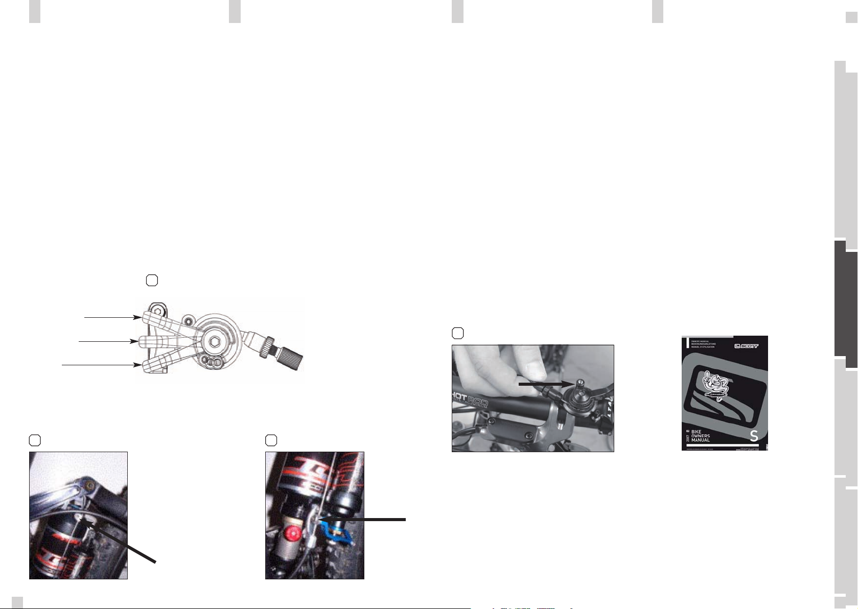
You will find following positions on the remote lever:
[1]
In the drawing of the shock and remote lever, shown
below, you will see the parts indicated with numbers
which will be used in the manual for the adjustment
and set-up. [2] [3]
S1 Upper Shock Bolt
S2 Lower Shock Bolt
S3 Piggy-Back
S4 Shock Housing
S5 Rebound-Screw
S6 Positive Chamber Valve
S7 Negative Chamber Valve
S10 Cable Clamping Screw
S11 Traction Mode Lever
S12 Shock Piston
L1 Remote Lever
L2 Remote Control Cable
L3 Tension Screw
L4 Allen Screw
S8 Cable Fixation Screw
S9 Lock Out Lever
2 3
S1
02-03
ENGLISH
02
Position lockout
Traction mode
All travel
S7
1
S4
S12
S5
Traction Control-Functions
S9
S8
S6
L3
S3
S10
S11
S2
Genius Shock Remote Lever
L2
L4
L1
DEUTSCH
FRANÇAIS
03
Page 4
BASIC SET-UP OF THE REMOTE
CONTROL OF GENIUS TC SHOCK PLEASE NOTE
1.Put the remote lever (L1) to position “lock-out”. [1]
2. Fix the remote control cable (L2) with the cable fixation
screw (S8) using a 3mm allen key (tightening torque:
3 Nm) on the lock out lever (S9). [3]
3.Put the remote lever now to position “Traction
Mode”. [1]
4.Fix the cable clamping screw (S10) using a 3mm allen
key (tightening torque 3Nm) on the traction mode lever
(S11). [4]
1
Position lockout
Traction mode
All travel
5.When putting now the remote lever to position “All
Travel” the cable will pull the traction mode lever downward and the shock will offer now the full travel. Check
now the set-up for perfect function of remote lever and
shock
6.In case you want to fine-tune the brake-away power
of the remote lever, you can do this by using a 2mm
allen key and by turning the allen screw (L4). In case
you want to readjust the tension of the remote control
cable you can do this by using the tension screw (L3).
[5]
5
2 mm allen keg
Please clean regularly after riding off-road the shock
piston (S12) and all other parts in motion of the shock
with a soft and wet cloth to prevent from excessive
wear and tear.
RECOMMANDED TOOLS FOR
THE SHOCK SET-UP
For the set-up of the shock we recommend to use
the tools listed below:
- a shock pump with a scale up to 20 bars/300 psi
with a special air valve connector preventing from
air getting away while removing the pump from
the shock valve and granting exact air pressure.
-Therefore we recommend the Scott Shock Pump
which you can order at your local Scott-Dealer
with parts number 15.1.834.208.0.000
- the SAG-Boy on the back of this manual
ENGLISH
Traction Control-Functions
3 4
04
DEUTSCH
FRANÇAIS
05
Page 5
SET-UP OF POSITIVE AIR
CHAMBER GENIUS TC SHOCK
SET-UP OF NEGATIVE AIR
CHAMBER GENIUS TC SHOCK
IMPORTANT:
For all adjustments of the air spring
the lockout lever has to be in position
“all travel”.
The positive air chamber contains the air-spring you
“sit-on” while riding. [7]
To adjust the air pressure of the positive chamber of
the Scott Genius Shock please refer to the following
instruction:
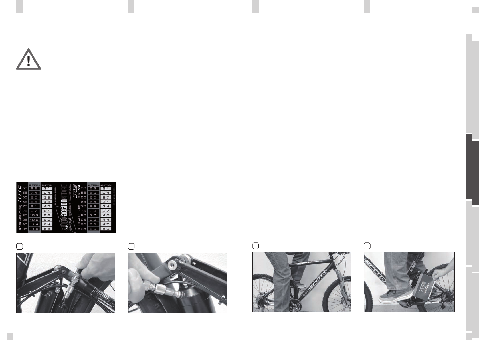
1. Remove the valve cap of the black valve (S6) located
on the Piggy-Back (S3).
2. Mount the shock pump with its adaptor on the valve
3. Pump the recommended pressure into the Piggy-Back.
On the housing of the Piggy-Back you will find a table
showing in the black colored areas the recommended
air pressure of the positive chamber according to the
rider’s weight.
4. When you reached the needed pressure remove the
pump and put the valve cap on the valve.
The negative air chamber contains the air-spring
influencing the brake-away and characteristic while
absorbing shocks. A too high brake-away can cause
an non-secure and uncomfortable ride. [8]
To adjust the air pressure of the negative chamber of the
Scott Genius Shock please refer to the following instruction:
1. Remove the cap of the silver valve (S7) located on the
shock housing (S4).
2. Mount the shock pump with its adaptor on the valve.
3. Pump the recommended pressure into the shock housing. On the housing of the piggy-back you will find a
table showing in the silver colored areas the recommended air pressure of the negative chamber according
to the rider’s weight.
4. When you reached the needed pressure remove the
pump and put the valve cap on the valve.
We recommend to make sure that the pressure balance
between positive and negative chamber follows the
recommendations shown on the piggy-back.
Not doing so may cause a loss in performance or comfort
or may result in damage of the shock.
After adjusting positive and negative chamber according
to the rider’s weight you can double check by using the
SAG-Boy, which is on the back of the manual, if the SAG
(negative travel) is well adjusted.
The negative travel is important when crossing grooves
or holes on the trail.
If the bike is well adjusted the rear wheel and the swingarm will roll through the groove without the mainframe
moving.
The SAG should be 15-20% of the travel for race oriented
riders and 20-25% of the travel for comfort oriented
riders.
The SAG-Boy indicates the recommended eye-toeye distance of the shock bolts of the different
Genius models.
To check the adjustment, please follow as shown
below:
1. Sit on the bike, put your feet on the pedal. [9]
2. Ask a second person, to put the color beam of
the SAG-Boy, recommended for your bike model,
aside the eye-to-eye distance of the shock bolts.
3. If the distance between the bolts is corresponding to the length of the color beam, the air pressure is matching to your weight
4. If the distance between the bolts is shorter
than the length of the color beam, the air pressure
of the positive chamber is too high and should be
carefully reduced by using the bleed knob of the
shock pump until the measures are corresponding.
[10]
5. If the distance between the bolts is longer than
the length of the color beam, the air pressure of
the positive chamber is too low and should be
increased by using the shock pump until the measures are corresponding.
ENGLISH
7 8
Positive Air Chamber Negative Air Chamber
06
109
DEUTSCH
FRANÇAIS
07
Page 6

SET-UP OF REBOUND
GENIUS TC SHOCK
MORE DETAILS ABOUT SHOCK
SET-UP
“Rebound” describes the speed the shock comes back
to its original length after absorbing an obstacle.
By using the red rebound screw (S5) you can adjust the
rebound step by step.
Please refer to the following instruction:
Ride your bike off a sidewalk (remain in the saddle)
and check how many times it bounces.
1. If it bounces 1-2 times, the set up is good.
2. If it bounces more than 3 times the rebound is too
fast. Turn the screw 1-2 “clicks” clockwise.
3. If it does not bounce the rebound is too slow. Turn
the screw 1-2 “clicks” counter clockwise. [11]
In case you want more exact numbers of the shock air
pressure than shown on the decal on the piggy-back or
you’re looking for tuning hints including different shock
characteristics of the Genius Shock, please have a look
at
www.scott-sports.com
In addition you can download this tuning program on
your pc.
ENGLISH
08
11
DEUTSCH
FRANÇAIS
Rebound knob
09
Page 7

GENIUS LC-R SHOCK
TRACTION CONTROL FUNCTIONS
Lockout
Full Travel
BASIC SET-UP OF THE REMOTE
CONTROL OF GENIUS LC-R SHOCK
The heart of the LC-R-System is the newly developed
and innovative Scott Genius LC-R Shock, offering two
functions:
By using the lock out lever on top of the shock body you
can choose between following functions:
1. ALL TRAVEL MODE: full travel of 100mm on Reflex
FX models.
2. LOCK OUT MODE: the shock is locked; climbing on
asphalt roads is now possible without any power loss.
Simultaneously a blow-off-system prevents the shock
being damaged in case the rider did not open the system while crossing obstacles.
S1 Upper Shock Bolt
S2 Lower Shock Bolt
S3 Shock Housing
S4 Rebound-Screw
S5 Negative Chamber Valve
S6 Positive Chamber Valve
S8 Allen Screw 3mm
S9 Lock-Out Lever
S10 Shock Piston
L1 Remote Lever
L2 Remote Control Cable
L3 Tension Screw
L4 Allen Screw
1.Put the remote lever (L1) to position “Lockout”. [1]
2. Fix the remote control cable (L2) with the cable fixation
screw (S8) using a 3mm allen key (tightening torque:
3 Nm) on the lock out lever (S9).
3.When putting now the remote lever to position “All
Travel” the cable will pull the Lockout lever downward
and the shock will offer now the full travel. Check now
the set-up for perfect function of remote lever and
shock
6.In case you want to fine-tune the brake-away power
of the remote lever, you can do this by using a 2mm
allen key and by turning the allen screw (L4). In case
you want to readjust the tension of the remote control
cable you can do this by using the tension screw (L3).
[2]
1
2
ENGLISH
2 mm allen keg
10
S1
S9
S8
S3
L3
L2
L4
L1
DEUTSCH
S4
S2
Genius LC-R Shock
S10
FRANÇAIS
Remote Lever
11
Page 8

SET-UP OF POSITIVE AIR
CHAMBER GENIUS LC-R SHOCK
SET-UP OF NEGATIVE AIR
CHAMBER GENIUS LC-R SHOCK
IMPORTANT:
For all adjustments of the air spring
the lock out lever has to be in position “all travel”/open
The positive air chamber contains the air-spring you
“sit-on” while riding. [7]
To adjust the air pressure of the positive chamber of
the Scott Genius Shock please refer to the following
instruction:
1. Remove the valve cap of the black valve (S5) located
on the lower end of shock housing (S3)
2. Mount the shock pump with its adaptor on the valve
3. Pump the recommended pressure into the positive
chamber. On the housing of the shock you will find a
table showing in the black colored areas the recommended air pressure of the positive chamber according
to the rider’s weight. Sketch of shock housing decal
4. When you reached the needed pressure remove the
pump and put the valve cap on the valve
The negative air chamber contains the air-spring
influencing the brake-away and characteristic while
absorbing shocks. A too high brake-away can cause an
non-secure and uncomfortable ride.
[8]
To adjust the air pressure of the negative chamber of
the Scott Genius LC-R Shock please refer to the following instruction:
1. Remove the cap of the silver valve (S6) located on
the upper end of the shock housing (S3)
2. Mount the shock pump with its adaptor on the valve
3. Pump the recommended pressure into the shock housing. On the housing of the shock you will find a table
showing in the silver colored areas the recommended
air pressure of the negative chamber according to the
rider’s weight. Sketch of shock housing decal
4. When you reached the needed pressure remove the
pump and put the valve cap on the valve.
We recommend to make sure that the pressure balance
between positive and negative chamber follows the
recommendations shown on the shock housing.
Not doing so may cause a loss in performance or comfort or may result in damage of the shock.
After adjusting positive and negative chamber according to the rider’s weight you can double check by
using the SAG-Boy, which is on the back of the manual,
if the SAG (negative travel) is well adjusted.
The negative travel is important when crossing grooves
or holes on the trail.
If the bike is well adjusted the rear wheel and the swingarm will roll through the groove without the mainframe
moving.
The SAG should be 15-20% of the travel for race oriented riders and 20-25% of the travel for comfort oriented
riders.
The SAG-Boy indicates the recommended eye-to-eye
distance of the shock bolts of the different Genius
models.
To check the adjustment, please follow as shown below:
1. sit on the bike, put your feet on the pedal [9]
2. ask a second person, to put the color beam of
the SAG-Boy, recommended for your bike model,
aside the eye-to-eye distance of the shock bolts.
- if the distance between the bolts is corresponding
to the length of the color beam, the air pressure is
matching to your weight
- if the distance between the bolts is shorter than
the length of the color beam, the air pressure of
the positive chamber is too high and should be
carefully reduced by using the bleed knob of the
shock pump until the measures are corresponding
[10]
- If the distance between the bolts is longer than
the length of the color beam, the air pressure of
the positive chamber is too low and should be
increased by using the shock pump until the measures are corresponding.
ENGLISH
7 8
S5
Positive Air Chamber Negative Air Chamber
12
109
DEUTSCH
S6
FRANÇAIS
13
Page 9

SET-UP OF REBOUND
GENIUS LC-R SHOCK
MAINTENANCE / SERVICE GUIDE
“Rebound” describes the speed the shock comes back
to its original length after absorbing an obstacle.
By using the red rebound screw (S4) you can adjust the
rebound step by step.
Please refer to the following instruction:
Ride your bike off a sidewalk (remain in the saddle)
and check how many times it bounces.
1. If it bounces 1-2 times, the set up is good.
2. If it bounces more than 3 times the rebound is too
fast. Turn the screw 1-2 “clicks” clockwise
3. If it does not bounce the rebound is too slow.
Turn the screw 1-2 “clicks” counter clockwise.
Please clean regularly after riding off-road the shock
piston and all other parts in motion of the shock with
a soft and wet cloth or if needed with mild soap to
prevent from excessive wear and tear.
For maintenance and service please refer to the following
table:
Please check that the valve caps are always fixed
completely on the valves to avoid damages of the
valves or inner parts of the shock caused by dust.
ENGLISH
14
Maintenance period
11
New Every ride Every 8
hours
Every 40
hours
Every 1000
hours / min.
1 x year
DEUTSCH
Check of air pressure
Check of rebound
Clean shock bushings,
check for tear and wear,
grease
Change of oil/inspection
at Scott Shock Service
Clean shock housing
Clean Lockout mechanism
FRANÇAIS
Rebound Knob
15
Page 10

IMPORTANT
The Scott Genius Shock is pressurised. Never
open, disassemble or rework the shock. Only a
qualified and authorized Scott service staff/
shock service center should do this.
To open a shock which is under pressure can be
dangerous and may cause injuries!
The Scott Genius Shock always must be adjusted
to the rider’s weight to warrant perfect function.
Therefore check before every ride the shock for
fitting air pressure.
Riding a defective or not properly working shock
can result in the loss of control over the bike and
may cause severe or dangerous injuries!
In case you want to disassemble the shock from the
bike for service or other reasons please note the recommended tightening torque of 10Nm for the shock bolts.
Scott recommends strongly the use of a torque key
to prevent from damages on shock, shock bushings
or frame.
In addition the shock bolts should be fixed with Loctite
medium (blue) to prevent the bolts from getting unscrewed.
Damages caused by improper assembly or bad maintenance as mentioned above, are not covered by warranty.
Once the recommended check up is made by Scott or a
shock service authorized by Scott, it is reported in the
maintenance schedule at the end of the manual, which
will then enable you to claim for warranty within the
warranty period.
The owner of the shock is responsible for the costs
of the service.
To ship the shock to Scott or the shock service
authorized by Scott please contact your local Scott
dealer.
ENGLISH
16
DEUTSCH
FRANÇAIS
17
Page 11

WARRANTY
Model ________________________
Year ________________________
Size ________________________
Frame ________________________
SCOTT warrants its Genius Shock for two years for
defects in material and/or workmanship. The warranty
period starts at the day of purchase of the completely
assembled bike or of the Genius Shock. This warranty
is limited to the first buyer, what means the first person
who uses the bike and only with the use it was made
for. The bike or the shock is to purchase via authorized
SCOTT-dealers to the exclusion of purchases via internet
auctions.
It is obligatory to give a copy of the bill of purchase
together with the defective shock in case of a warranty
claim given that it provides evidence of purchase.
Otherwise no warranty is granted.
In case of a warranty claim the decision to repair or to
replace the defective shock is up to SCOTT. Non defective parts will only be replaced at the guarantee’s own
expense.
Following wear and tear shock elements are not covered
by the warranty:
- all seals and mud scrapers
- all piston bushings and sliders
- the surface of the piston
- the fixation bushings
- the shock bolts
Following damages are not covered by the warranty:
- improper use
- damages on the piston seals caused by high
pressure washers
- damages in the surface of the shock or piston
caused by cable housings, stones or crashes
- any attempts to disassemble the rear shock
- changes in technical specifications
- oil changes not made at SCOTT or Shock Service
Centers authorized by SCOTT
- neglecting the service and maintenance periods
mentioned in the maintenance schedule of this
manual (please refer to the maintenance schedule
listed above)
Claims must be made directly through an authorized
dealer with the protocol of handing over. For information regarding the nearest dealer, write or call
this company or the national SCOTT distributor.
Under reservation of national warrant of merchantability.
ENGLISH
18
DEUTSCH
FRANÇAIS
19
Page 12

SCOTT SERVICE PLAN
SCOTT SERVICE PLAN
Model ___________________
Year ___________________
Size ___________________
Frame ___________________
Service comment :
____________________
____________________
____________________
____________________
____________________
____________________
____________________
____________________
Model ___________________
Year ___________________
Size ___________________
Frame ___________________
Service comment :
____________________
____________________
____________________
____________________
____________________
____________________
____________________
____________________
ENGLISH
Date of Service:
20
Dealers Signature:
Date of Service:
DEUTSCH
Dealers Signature:
FRANÇAIS
21
Page 13

SCOTT SERVICE PLAN
SCOTT SERVICE PLAN
Model ___________________
Year ___________________
Size ___________________
Frame ___________________
Service comment :
____________________
____________________
____________________
____________________
____________________
____________________
____________________
____________________
Model ___________________
Year ___________________
Size ___________________
Frame ___________________
Service comment :
____________________
____________________
____________________
____________________
____________________
____________________
____________________
____________________
ENGLISH
Date of Service:
22
Dealers Signature:
Date of Service:
DEUTSCH
Dealers Signature:
FRANÇAIS
23
Page 14

SCOTT SERVICE PLAN
SCOTT SERVICE PLAN
Model ___________________
Year ___________________
Size ___________________
Frame ___________________
Service comment :
____________________
____________________
____________________
____________________
____________________
____________________
____________________
____________________
Model ___________________
Year ___________________
Size ___________________
Frame ___________________
Service comment :
____________________
____________________
____________________
____________________
____________________
____________________
____________________
____________________
ENGLISH
Date of Service:
24
Dealers Signature:
Date of Service:
DEUTSCH
Dealers Signature:
FRANÇAIS
25
 Loading...