

Page 1

Copy No.:
Instruction Manual
Model No. : Scott Edge Reinforcer.................
Year of Manufacture : 2006.......
Manufactured by :..........
Document Number : R99999--2........
Issue : 1.....................
Date of Issue : July 2006..............
Page 2

ISSUE NOTE
This is Issue 1; Date of Issue: July 2006
Copyright 2006
Page 3

Table of Contents
III
Scott Edge Reinforcer
TABLE OF CONTENTS
1 INTRODUCTION & SAFETY 1--1...........................................................
1.1 Introduction 1--3....................................................................
1.1.1 Scott Edge Reinforcer Machine Specifications and Utility Requirements 1--4..............
1.2 General Safety Guidelines 1--5.......................................................
1.3 Safety Features 1--6.................................................................
1.3.1 Emergency Stop 1--6.............................................................
1.3.2 Stop and Safe 1--6...............................................................
1.3.3 Main Power Switch 1--6...........................................................
1.3.4 Guards and Covers 1--7...........................................................
1.4 Warnings, Cautions & Notes 1--8.....................................................
1.4.1 Warnings 1--8....................................................................
1.4.2 Cautions 1--8....................................................................
1.4.3 Notes 1--8.......................................................................
1.5 On Machine Warnings 1--9...........................................................
1.5.1 Hazards 1--9....................................................................
1.6 Safety Procedures 1--10..............................................................
1.6.1 Appropriate Dress 1--10............................................................
1.6.2 Keep Area Clean 1--10.............................................................
1.6.3 Grease and Oil 1--10..............................................................
1.6.4 Manual Usage 1--10...............................................................
2 INSTALLATION 2--1......................................................................
2.1 Installation Requirements 2--3........................................................
2.2 Pre-Installation Requirements 2--4....................................................
2.3 Uncrating & Placement 2--5..........................................................
2.3.1 Main Machine 2--5................................................................
2.3.2 Install Discharge Paper Tray 2--5...................................................
2.3.3 Start--Up & Tools Kit 2--5..........................................................
2.4 Electrical Connection 2--5...........................................................
2.4.1 Electrical Connections 2--5........................................................
3 OPERATION 3--1.........................................................................
3.1 GENERAL INFORMATION 3 --3........................................................
3.1.1 Before Operating the Machine 3--3.................................................
3.2 Operating Controls and Indicators Descriptions 3--5...................................
3.2.1 Operator’s Control Panel Layout 3--5................................................
3.2.2 Machine Stopping Device 3--5.....................................................
3.2.3 Additional Machine Controls 3--8...................................................
3.2.4 Brake and Clutch Controllers 3--8...................................................
3.3 Set Up Machine for Production 3--9...................................................
3.3.1 Set Heat Controller For Running Heat Seal Tapes 3--9.................................
3.3.2 Threading Mylar Into Machine 3--9..................................................
Page 4

Table of Contents
IV
Scott Edge Reinforcer
3.3.3 Adjusting Tape Position On Paper 3--12..............................................
3.3.4 Adjusting Delivery Tray 3--12........................................................
3.3.5 Adjusting Cut--Off Guide Finger 3--13................................................
3.3.6 Testing the Cut Off Guide Finger 3--14...............................................
3.3.7 Feeding Machine By Hand 3--15.....................................................
3.3.8 To Remove the Table 3--16.........................................................
3.3.9 Adjusting Automatic Brake On Reel Holder 3--19.......................................
3.3.10 Adjustment Of Brake & Clutch Potentiometers 3--19....................................
3.3.11 Changing From Heavy Stocks To Light Weight Paper Stocks 3--20.......................
3.3.12 Tips For Feeding Lightweight Stocks 3--22............................................
3.3.13 Adjustment of the Trip Switch 3--23..................................................
3.4 Using Self--Adhesive Tape 3--24.......................................................
3.4.1 Recommended Uses For Pressure Sensitive Tape 3--24................................
3.4.2 When to use Pressure Sensitive Polyester Tape instead of Heat Seal Polyester Tape 3--24..
3.4.3 Installing Self--Adhesive Drum Assembly 3--24........................................
3.4.4 Adjustment For “Tracking” 3--27.....................................................
3.4.5 Machine Cleaning 3--29............................................................
4 MAINTENANCE 4--1......................................................................
4.1 Spare Parts 4--3.................................................................
4.1.1 Machine Lubrication 4--4..........................................................
4.1.2 Installing New Trip Switch 4--6.....................................................
4.1.3 Replacing Cut--Off Knives 4--8.....................................................
4.1.4 Removing & Installing the Upper and Lower Cut--Off Knife Assembly 4--9................
4.1.5 Packaging Instructions For Returning Assemblies to Factory for Repairs 4--12.............
4.1.6 Instructions for Installing the Two Cut--off Assemblies 4--12..............................
5 PARTS 5-1..............................................................................
5.1 Base Assembly 5-4.....................................................................
5.2 Base Assembly 5-6.....................................................................
5.3 Feed Plate & Paper Guide Assembly 5-8...................................................
5.4 Gear Belt Idler Assembly 5-10.............................................................
5.5 Main Drive Shaft Assembly 5-12...........................................................
5.6 Motor Assembly 5-14.....................................................................
5.7 Belt Assembly 5-16......................................................................
5.8 Cover Assembly 5-18....................................................................
5.9 Front Roller Belt Assembly 5-20...........................................................
5.10 Tension Arm Assembly 5-22.............................................................
5.1 1 Support Mounting Assembly 5-24..........................................................
5.12 Electric Motor Assembly 5-26............................................................
5.13 Conveyor Belt Assembly 5-28............................................................
5.14 Pivot Shaft Assembly 5-30...............................................................
5.15 Bearing Housing & Lower Appling Shaft Assembly 5-32......................................
5.16 Slip Ring & Brush Assembly 5-34..........................................................
5.17 Upper & Lower Knife Holder Assembly 5-36................................................
5.18 Housing Assembly 5-38.................................................................
5.19 Sprocket Mounting Assembly 5-40........................................................
5.20 Plastic Mounting Hub Assembly 5-42......................................................
5.21 Roller Mounting Block Assembly 5-44.....................................................
Page 5

Table of Contents
V
Scott Edge Reinforcer
5.22 Pressure Sensitive Tape Assembly 5-46...................................................
5.23 Leg Extension Assembly 5-48...........................................................
5.24 Rail & Leg Assembly 5-50...............................................................
5.25 Leg Extension Assembly 5-52...........................................................
6 SCHEMATICS 6-1........................................................................
Page 6

1 Introduction & Safety
1--1
Edge Reinforcer Issue 1
1 INTRODUCTION & SAFETY
Edge Reinforcer Issue 1
Page 7

1 Introduction & Safety
1--2
Edge Reinforcer Issue 1
Page 8

1 Introduction & Safety
1--3
Edge Reinforcer Issue 1
1.1 Introduction
The Scott Edge Reinforcer machine lays reinforcing tape within the outside edges of the sheet at the rate
of up to 3,000 sheets per hour.
Fig. 1 -1. Edge Reinforcer
Fig. 1-2. Machine Rear View
Page 9

1 Introduction & Safety
1--4
Edge Reinforcer Issue 1
1.1.1 Scott Edge Reinforcer Machine Specifications and Utility Requirements
Model Scott Edge Reinforcert
Speed
Up to 3,000 sheets per hour.
Sheet Size
431.8 mm (17”) WIDTH x ANY LENGTH MAXIMUM
88.9 mm x 203.2mm (3--1/2” WIDTH x 8”) LENGTH MINIMUM
Paper
32lb. Bond to 17 Point Board
Plastic Length
203.2 mm (8”) MINIMUM
ANY LENGTH MAXIMUM
Plastic
14.3 mm -- 19mm (9/16” -- 3/4”)
Motor
FEED: 1/3 HP
DRIVE: 1/6HP
Electrical Requirements
15 AMPS, 120 VAC SINGLE PHASE, 60HZ (50HZ Option Available)
Decibel Rating
90 DB
Dimensions
L -- 1320.8 MM (52”)
W -- 812.8 MM (32”)
H -- 1422 MM (56”)
Shipping Weight
Approximately 152kg (335 lbs)
Warranty
One year against defects in parts and workmanship. Labor Not Included.
Page 10

1 Introduction & Safety
1--5
Edge Reinforcer Issue 1
1.2 General Safety Guidelines
Providing a safe working environment for operating your machine is the responsibility of the user. The
suggested precautions, material safety data and other suggestions that follow do not have preference over
the user’s own plant practices, regulations or safety committee recommendations.
Personal injury and equipment damage can be avoided by the continued adherence to the safety features
provided with this machine and in keeping with the necessary governmental requirements. The guarding
and interlocking safety switches have been installed on the machine for the operator’s safety. These items
should be maintained in good working order by the user.
It is assumed that the user’s safety department has established a safety program that is in keeping with a
complete analysis of industrial hazards. Before installing and operating or performing maintenance and
clean--up procedures on the machine, it is suggested that the safety program be reviewed to ensure that it
covers the possible hazards that might occur with the operation of this machine.
Due consideration must be given to those hazards which arise from the presence of electrical power, high
temperature, and cleaning materials used in the operational areas of the machine. Proper installation and
care of protective devices and over--pressure protective equipment should be considered an essential part of
any safety program.
Special lock--out features are to prevent the possibility of applying power to the equipment at any time when
maintenance work is in progress.
In general, personnel should be guided by all basic rules of safety associated with the equipment and the
process. It should be further understood that information contained in this manual does not relieve operating
and maintenance personnel of the responsibility of exercising normal good judgment in operating and care of
the machine and its attendant equipment.
Page 11

1 Introduction & Safety
1--6
Edge Reinforcer Issue 1
1.3 Safety Features
E--STOP
Fig. 1-3. Know Where Emergency Stop Button
is Located
These safety features are to be used in conjunction
with the installation, operation and maintenance
instructions contained in this manual.
1.3.1 Emergency Stop
Stops machine drive immediately. This pushbutton
must be manually pulled out to reset.
STOP
Fig. 1 -4. Know How to Stop Machine & Set Key
Switch to SAFE
1.3.2 Stop and Safe
The machine operator, clean--up and maintenance
personnel MUST be shown how to stop the
machine and place the SWITCH on the operator’s
CONTROL PANEL in the OFF mode whenever
machine is accessed or clean--up operations are
performed.
Fig. 1-5. Turn Machine Off Before Making
Adjustments
1.3.3 Main Power Switch
If machine is to be shut down for adjustments or
repairs, turn the power supply to the machine off.
Page 12

1 Introduction & Safety
1--7
Edge Reinforcer Issue 1
Fig. 1-6. Guards Must Be In Place to Run
Machine
1.3.4 Guards and Covers
All safety guards, protective screens and covers
MUST be in place and securely fastened before
operating the machine.
Page 13

1 Introduction & Safety
1--8
Edge Reinforcer Issue 1
1.4 Warnings, Cautions & Notes
In order to emphasize certain areas in the interest of personal safety and a properly operated and maintained
machine, you will encounter the words WARNING, CAUTION, and NOTE throughout this manual.
WARNING!
Fig. 1 -7. Warnings Indicate Personal Danger
1.4.1 Warnings
AN OPERATING PROCEDURE,
PRACTICE, ETC. WHICH IF NOT
CORRECTLY FOLLOWED, COULD
RESULT IN PERSONAL INJURY OR
LOSS OF LIFE.
WARNING!
CAUTION!
Fig. 1 -8. Cautions Indicate Potential Damage to
Equipment
1.4.2 Cautions
AN OPERATING PROCEDURE,
PRACTICE, ETC. WHICH, IF NOT
STRICTLY OBSERVED, COULD RESULT
IN DAMAGE TO OR DESTRUCTION OF
EQUIPMENT.
CAUTION!
Note !
Fig. 1-9. Notes Indicate Essential Information
1.4.3 Notes
An Operating Procedure, Condition,
etc. Which is Essential To Highlight.
Note !
Page 14
1 Introduction & Safety
1--9
Edge Reinforcer Issue 1
1.5 On Machine Warnings
Fig. 1 -10. Burn Hazard --- Heat Rollers
1.5.1 Hazards
Observe Hazard signs. There is burn hazard sign
on top of the heat roller unit.
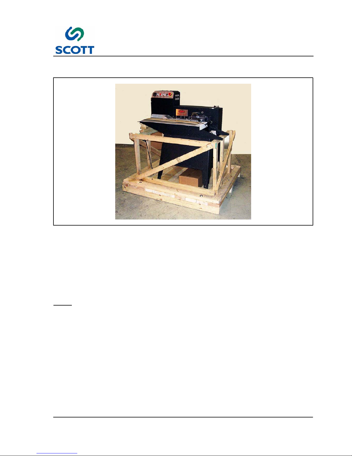
Fig. 1 -11. Voltage Warning
There is a hazardous voltage warning on the main
electrical cabinet.
Page 15

1 Introduction & Safety
1--10
Edge Reinforcer Issue 1
1.6 Safety Procedures
Fig. 1 -12. Wear Proper Clothing
1.6.1 Appropriate Dress
Personnel working in the machine operation area
must remove jewelry and neckties. Personnel
must wear clothing appropriate for the work area.
Fig. 1-13. Keep Work Area Clean and Neat
1.6.2 Keep Area Clean
Loose materials, tools and equipment, not
essential to the operation of the machine, must be
removed from the machine work area.
Fig. 1-14. Clean Up Oil and Grease Spills
1.6.3 Grease and Oil
Clean up all oil and grease spills around the
machine work area.
Fig. 1 -15. Read Manuals First
1.6.4 Manual Usage
Read and understand the instructions in the
manual before operating, adjusting or servicing
machine.
Page 16

2 Installation
2--1
Edge Reinforcer Issue 1
2 INSTALLATION
Edge Reinforcer Issue 1
Page 17

2 Installation
2--2
Edge Reinforcer Issue 1
Page 18
2 Installation
2--3
Edge Reinforcer Issue 1
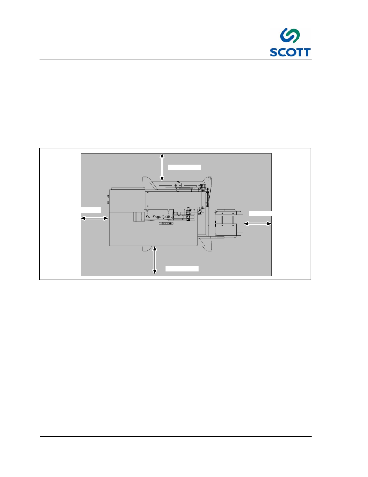
2.1 Installation Requirements
Fig. 2 -1. Scott Edge Reinforcer on Shipping Skid
All procedures in this section provide advance planning and site preparation data for installation of the Scott
Edge Reinforcer. Environmental requirements, unpacking instructions, electrical and physical specifications
are included. This information should be used as a reference during the development of site preparation
plans before you install your machine.
If any questions arise while performing any of the following procedures, contact:
Note ! A forklift is required to lift the machine off the shipping skid and place it on the floor.
Page 19
2 Installation
2--4
Edge Reinforcer Issue 1
2.2 Pre-Installation Requirements
The environmental requirements of the Scott Edge Reinforcer must be considered well in advance of the
actual installation. Providing a well suited operating environment will help ensure a trouble free installation
process. Consideration should be given to the following items:
● Power, location and rating of power connections.
● Floor strength
● Level floor
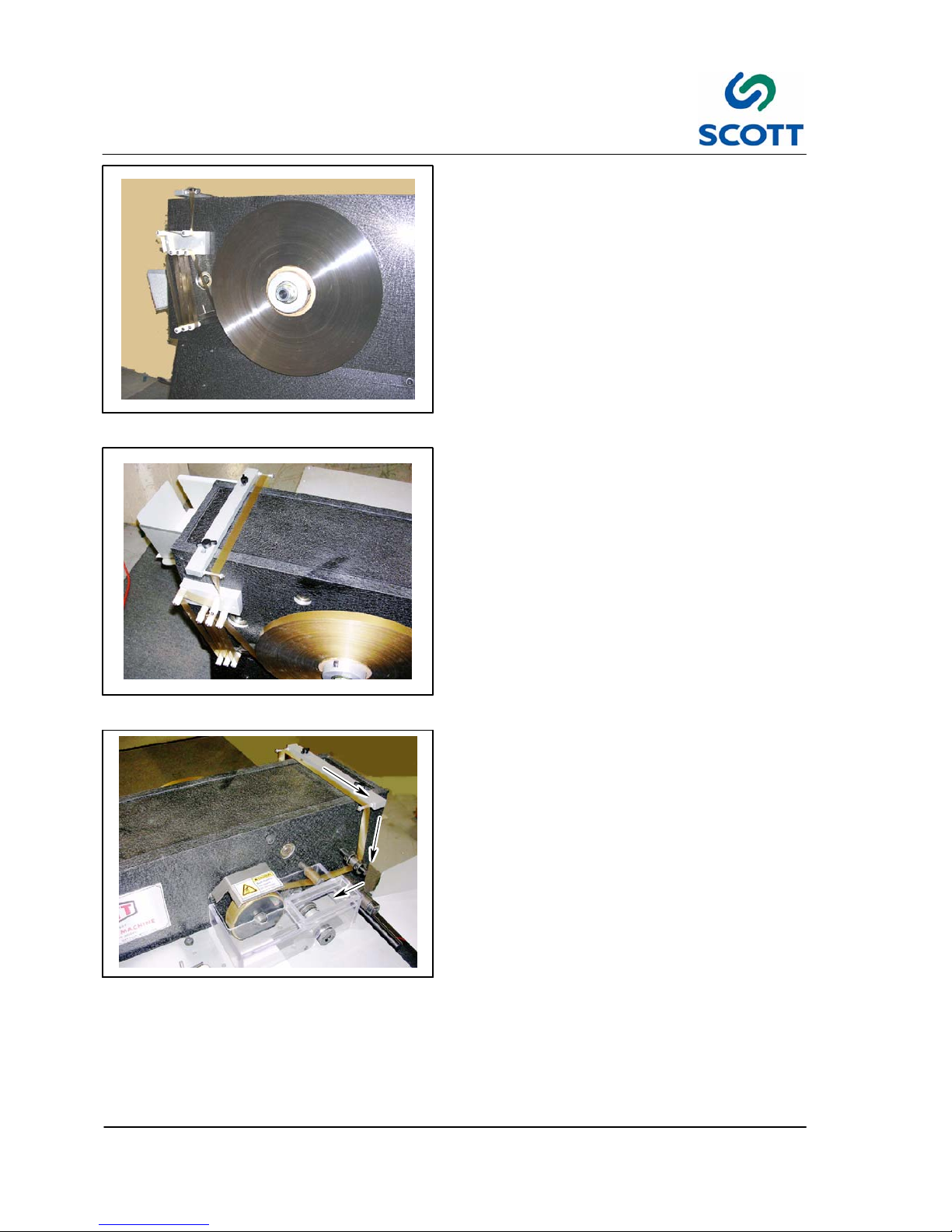
● Adequate space must be provided around all four sides of the machine to permit normal operation and
maintenance procedures. The figure shows the minimum space required.
3
12
3’ (914mm)
3’ (914mm)
3’ (914mm)
3’ (914mm)
Fig. 2 -2. Scott Edge Reinforcer Space Requirements
● Space should be allocated near the paper tray for a small table that can be used for small jobs, samples,
etc.
● Provide plenty of space In front of the machine so large jobs can be easily moved in and out with skids or
carts.
Page 20

2 Installation
2--5
Edge Reinforcer Issue 1
2.3 Uncrating & Placement
The machine will arrive in one crate. Inspect the external condition of the crates for visible signs of damage
before opening. If damage is noticeable, notify the carrier and Scott Equipment before proceeding with the
installation.
To assist in the ease of installation, the machine is disassembled prior to shipping and requires some minor
assembly before the machine is operational.
2.3.1 Main Machine
Step: 1. Remove metal banding straps from cardboard surrounding shipping crates.
CAUTION
! EXTREME CAUTION MUST BE EXERCISED WHEN MOVING MACHINE TO INSTALLATION
LOCATION TO PREVENT DAMAGE.
Step: 2. Use a fork lift to place the main machine shipping skid near the designated floor area of operation.
Step: 3. Remove lag screws holding machine to shipping skid.
Step: 4. Raise main machine with fork lift, remove shipping skid assembly from under machine.
Step: 5. Lower main machine to floor.
Step: 6. Remove all protective wrapping from machine.
Step: 7. Remove front and rear covers and place them aside so they won’t be damaged.
Fig. 2 -3. Discharge Paper Tray
2.3.2 Install Discharge Paper Tray
The discharge paper tray is shipped uninstalled.
2.3.3 Start--Up & Tools Kit
The machine is shipped a variety of tools and parts required to set the machine up for production. Unpack
box and lay all parts from kit on table top to inventory against the included packing list.
2.4 Electrical Connection
2.4.1 Electrical Connections
The machine requires 110V 15 Amp Service.
Electricity to the machine is delivered through “United States” style plug.
Note ! Electrical cords going to machine should be routed overhead and be of sufficient height to
allow personnel to travel around entire machine without interference.
Page 21

3 Operation
3--1
Edge Reinforcer Issue 1
3 OPERATION
Edge Reinforcer Issue 1
Page 22

3 Operation
3--2
Edge Reinforcer Issue 1
Page 23

3 Operation
3--3
Edge Reinforcer Issue 1
3.1 GENERAL INFORMATION
3.1.1 Before Operating the Machine
AVOID SERIOUS INJURY OR EQUIPMENT
DAMAGE. RESTRICT OPERATION OF THIS
MACHINE TO TRAINED, QUALIFIED
PERSONNEL ONLY.
EACH OPERATOR SHOULD KNOW THE
LOCATION AND FUNCTION OF ALL
MACHINE STOPPING CONTROLS.
REVIEW MANUAL FOR EMERGENCY
STOP BUTTON LOCATION.
Do not attempt to operate the machine before reading and understanding the manual. Pay close attention to
all WARNINGS, CAUTIONS and NOTES. Failure to do so may cause serious injury and extensive machine
damage.
Read through the inspection and pre--start procedures before starting the machine. Make these checks part
of your routine to insure efficiency and quality during the production run.
Page 24

3 Operation
3--4
Edge Reinforcer Issue 1
Page 25

3 Operation
3--5
Edge Reinforcer Issue 1
3.2 Operating Controls and Indicators Descriptions
3.2.1 Operator’s Control Panel Layout
Fig. 3 -1. Control Panel
Fig. 3-2. Emergency Stop
3.2.2 Machine Stopping Device
3.2.2.1 Emergency Stop -- Red Pushbutton
Stops the machine drive immediately. The
Emergency Stop button is located on the
Operator’s Panel. After a stop, the button must be
manually pulled out before cycling can resume.
Page 26

3 Operation
3--6
Edge Reinforcer Issue 1
PROCESS VALUE
SCROLL KEY
RETURN KEY
SET
VAL UE
CON:
Control
Output
ALM:
Alarm
Output
Fig. 3-3. Heater Temperature Control
3.2.2.2 Heater Temperature Control
Controls wheel heat temperature by cycling power
to the heaters. The setpoint temperature is
adjusted by using the buttons below the indicator
display.
The controller maintains process parameters when
power is off.
Touch Keys Description Function
Scroll Key Advances the index display to the desired position.
Indexes advanced continuously and cyclically by
pressing this keypad.
Up Key Increases the parameter (Set Point or Other)
Down Key Decreases the parameter (Set Point or Other)
Return Key Resets the controller to its normal status. Also stops
auto--tuning, output percentage monitoring and
manual mode operation.
Press for 6 seconds
Long Scroll Allows more parameters to be inspected or
changed.
Press for 6 seconds
Long Return 1. Executes auto--tuning function.
2. Calibrates control when in calibration level.
Press and
Output Percentage
Monitoring
Allows the set point display to indicate the control
output value in percent.
Press and
for 6 seconds
Manual Mode Execution Allows the controller to enter the manual mode.
This can be used if the sensor fails.
Fig. 3-4. Heat On/Off Illuminated Push Button
3.2.2.3 Heater ON/OFF Push Button
ON -- When pushed, the button illuminates,
indicating roller heater is turned ON.
OFF -- When pushed again, the heater is turned
OFF.
Approximate warm up time for heater is 3--5
minutes.
Page 27

3 Operation
3--7
Edge Reinforcer Issue 1
Fig. 3-5. Stop Push Button
3.2.2.4 STOP -- Red Pushbutton
The pushbutton stops the machine drive. This is a
“soft” stop and is intended for planned stops, not
emergencies.
To reset after a stop, the button must be pushed
again so that the button is extended out.
Fig. 3-6. Feed ON/OFF Illuminated Push Button
3.2.2.5 Feed ON/OFF Illuminated Push Button
Pushing this button starts the conveyor drive motor
so that when sheets are hand fed, they will be
drawn into the machine.
The button will be illuminated when the feed in ON.
Fig. 3 -7. Drive Mode Selector Switch
3.2.2.6 Drive Mode Selector Switch
The Drive Mode Selector switch controls the drive
motor for the brake clutch which makes the heat
roller and cut off package operate.
JOG -- Used during maintenance and tape set up.
This is a manual override of the trip switch. The
conveyor must be running.
OFF -- Turns the drive conveyor off.
ON -- This is the normal production setting. The
Feed Button must also be turned on. When the
switch is in the ON position, the trip switch is
activated which, when a sheet is present, activates
the clutch to rotate one revolution to draw in one
sheet.
Page 28

3 Operation
3--8
Edge Reinforcer Issue 1
3.2.3 Additional Machine Controls
Fig. 3 -8. Additional Machine Controls
Fig. 3-9. Power ON/OFF Selector Switch
3.2.3.1 Power On/Off Selector Switch
Turns on main power to the machine.
Fig. 3 -10. Clutch Engaged Indicator Light
3.2.3.2 Clutch Engaged Indicator Light
The Clutch Engaged indicator light is useful for
timing sheets fed into the machine. The Clutch
Engaged light should turn off after each sheet fed.
Fig. 3-11. Clutch and Brake Potentiometers
3.2.4 Brake and Clutch Controllers
The controllers purpose is to change the
aggressiveness of the brake & clutch, making for
more gentle stops & starts.
For normal operation, set pot to lowest possible
setting (usually 5 or higher) so that the action of
the brake and clutch allows smooth, consistent
stopping and starting.
Page 29

3 Operation
3--9
Edge Reinforcer Issue 1
3.3 Set Up Machine for Production
Fig. 3 -12. Heat Controls
3.3.1 Set Heat Controller For Running
Heat Seal Tapes
The heat controller for the rollers is located on the
operator’s panel.
Step: 1. Set temperature to 190_F on Heat
Controller.
Step: 2. Turn the Heater to ON.
NOTE! The optimum temperature is between
190
_
- 200_F
Keep the temperature as low as
possible to prevent tape stretch and
the removal of water from the paper.
The heaters will come up to
temperature in about 3 to 5 minutes.
A
B
D
C
F
E
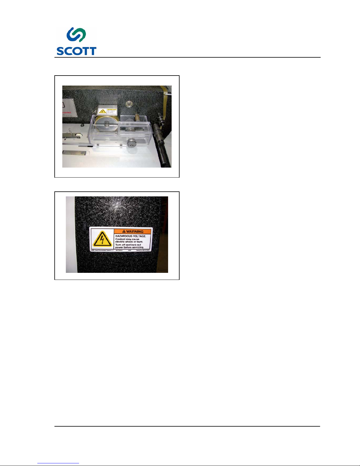
Fig. 3-13. Mylar Feed & Cut Area Locator
3.3.2 Threading Mylar Into Machine
A -- Strip Applying Roller
B -- Roller
C -- Cut Off Package
D -- Tape Position Roller
E -- Pull Out Roller
F -- Cross Over Roller
Page 30
3 Operation
3--10
Edge Reinforcer Issue 1
Fig. 3-14. Load Tape on Reel
CAUTION: When stringing the Heat Seal Tape,
care must be taken to twist the tape in the
correct manner so that the adhesive is facing
away from the strip - applying roller and that the
raw polyester is against it.
The polyester tape is on 3” cores.
Step: 1. Place the reel of tape on the reel holder.
Step: 2. You may use a small piece of
self--adhesive tape to fasten the end of
the polyester tape to the applying roller.
Fig. 3-15. Install Tape Thru Rollers
Step: 3. Interweave the end of the strip of tape
around the rollers over the top of the
machine and under the guide pins to the
“applying roller” as shown in Fig. 3-15. &
Fig. 3-16. .
Fig. 3-16. Attach Tape to Heat Applying Roller
as Shown
Page 31

3 Operation
3--11
Edge Reinforcer Issue 1
Fig. 3-17. Push the Feed Button
Step: 4. Push the Feed button.
Step: 5. Feed a single sheet of standard size
paper into the machine. This will cause
the end of the strip of tape to be drawn
around the strip applying roller.
Fig. 3-18. Turn the Drive Switch to ON
Step: 6. Turn Drive switch to on.
Step: 7. Remove the piece of self adhesive tape
from the roller and use it to fasten the
end of the tape to the sheet of paper.
Fig. 3 -19. Tape Ready to Apply
Step: 8. The machine is now threaded and is
ready to apply the polyester tape.
Note: Shown with guard removed for
clarity.
Page 32

3 Operation
3--12
Edge Reinforcer Issue 1
G
D
Fig. 3 -20. Tape Position Adjustments
3.3.3 Adjusting Tape Position On
Paper
There are two parts on the machine which
determine the distance the tape is applied from the
edge of the sheet:
Cross Over Bar (G) -- This guides the tape over
the top of the machine. This bar is mounted to the
gear box housing by two hand knobs. Loosening
the knobs will allow the bar to be moved back and
forth so that the position where the tape comes
down in front of the machine may be adjusted.
Tape Position Roller (D) -- The roller is mounted
on the guide spindle on the front of the machine
directly below the “cross--over arm”. By adjusting
this collar back and forth on its spindle, the tape
can be controlled so that it will be applied in the
correct position on the paper.
Fig. 3 -21. Insert Spring Loaded Pins in to
Mounting Holes
3.3.4 Adjusting Delivery Tray
The delivery tray may be adjusted for long or short
sheets. The tray is mounted on two spring--loaded
pins. To remove or change the position of the tray,
push the tray sideways and tilt so that the pins
come out of their sockets. You will see several
sockets in the main frame for different positions.
Fig. 3-22. Adjust for Paper Size
Step: 1. The sides of the paper tray should be set
up according to paper size. The
adjustment knobs are located on the
underside of the paper tray.
Step: 2. Taper the side of the adjustable tray
slightly toward the leading edge of the
paper.
Page 33

3 Operation
3--13
Edge Reinforcer Issue 1
Fig. 3 -23. Cut Off Finger
3.3.5 Adjusting Cut--Off Guide Finger
Start Up or Stock Size Changeover
When the machine is shipped from the factory, this
device is set properly for heavy sheets. For lighter
weight sheets, an adjustment is necessary to get a
proper cut. The cut off guide finger detects the
edge of the sheet for the knife to cut the film. The
cut--off guide finger is mounted in a circular holder
which allows it to be adjusted with respect to the
cut--off knife.
NOTE! In this position, you will find two
scribed lines on the two parts (at the
factory these lines are in line with
each other and it is from this point
you would change the position). You
can always get back to the original
position by lining up t he two lines
again.
Page 34

3 Operation
3--14
Edge Reinforcer Issue 1
Fig. 3-24. Run Sample Sheets -- Measure Cut
3.3.6 Testing the Cut Off Guide
Finger
When changing stocks it is sometimes necessary
to adjust the Cut Off Guide Finger.
To Test :
Step: 1. Run 3--5 sample sheets of stock.
Step: 2. Determine if the cut off guide finger is
cutting into the either the leading or the
trailing edge of the stock.
Step: 3. If there are cuts in the stock as shown in
Fig. 3-24. , measure the distance from
the edge of the sheet to the edge of the
cut. This will determine how much Cut
Off Guide FInger adjustment is
necessary.
Fig. 3-25. Loosen Guide Finger Set Screw
Step: 4. Loosen set screw securing guide finger in
place.
Fig. 3-26. Rotate Guide Finger Assembly
Dimension of Cut
Step: 5. Hold on to knife housing assembly while
rotating guide. Rotate guide finger the
approximate dimension that the cutter is
cutting into the paper edge.
Example: If the guide finger is cutting into the
leading edge of the paper 1/16th” then rotate the
guide finger 1/16th” clockwise.
● Rotate the guide finger clockwise to adjust
leading edge dimension.
● Rotate guide finger counterclockwise to adjust
trailing edge dimension.
Step: 6. Tighten set screw.
NOTE! Do Not Over tighten.
Step: 7. Test by running 3--5 more sheets.
Step: 8. Repeat until there is no cut on either
paper edge.
Page 35

3 Operation
3--15
Edge Reinforcer Issue 1
3.3.7 Feeding Machine By Hand
The only requirement for feeding is that the sheet be inserted near the left--hand guide. The machine will
automatically register the sheet against the left--hand guide so that it travels through the machine straight.
It is recommended that the operator start feeding at a moderate rate and gradually increase their feeding
speed of the machine.
The optimum feeding rate is to go at a speed so that the operator hears a “click” each time (when one cannot
hear the click, the operator is feeding too fast and will probably jam the machine).
NOTE! It is important that the operator
develop a regular good feeding rate
and not feed sheets too rapidly. If the
sheets are fed too rapidly, they may
overlap each other before they get to
the “spacer finger” which sometimes
may cause the sheets to stop at the
cut- off guide finger and jam the
machine.
NOTE! If you ever find Mylar wrapped around
the lower roller, it is because the
operator “over- fed” the machine,
caused a jam and allowed the Mylar to
wind around below. When this
happens, remove the Mylar which is
wound around the lower roller. This
does not always happen when the
machine jams, but it is a good idea to
check this after a jam.
Fig. 3-27. Fan Paper Stack
The feeding operation is very simple and is as
follows:
Sheets are fed one at a time from the feed station.
Step: 1. “Fan” the sheets and place them on the
feed board against the left--hand guide.
Fig. 3-28. Feed Sheet One at a Time
Step: 2. Pick up the back end of the sheet with
one hand and use the other hand to
insert the sheet into the machine.
Page 36

3 Operation
3--16
Edge Reinforcer Issue 1
3.3.8 To Remove the Table
Occasionally is will be necessary to remove the table to clear tape that has wrapped around lower pressure
roller.
CAUTION: The table is a precision part of the machine and must be handled with extreme care. The
operator must be very careful not to drop it or damage it in any way. even small dents or burrs on the
top surface may tend to snag the sheets as they go through and can cause operating difficulties.
Fig. 3-29. Jog Last Sheets Out of Machine and
Turn Feeder and Drive Off
To remove the table, do the following:
Step: 1. Cut the tape so that it is free of the roll.
Step: 2. Remove paper from the feeding area.
Step: 3. Jog the last sheets out of the machine.
Step: 4. Shut off the sheet Feed.
Step: 5. Turn the Drive switch to OFF.
Fig. 3-30. Remove the Cut Off Package Guard
Step: 6. Remove the Cut Off Package guard.
Page 37

3 Operation
3--17
Edge Reinforcer Issue 1
A
Fig. 3-31. Spacer Finger Should Be Horizontal
and Pointed Toward Front of Machine
Step: 7. With your hand, push the spacer finger
(A) so that it is in a horizontal position
(parallel to the table) and pointing toward
the front of the machine.
NOTE! There is a “flat” on the hub which
provides the clearance needed to lift
off table.
B
Fig. 3-32. Rotate the Cut Off Guide Finger
Above Table
Step: 8. Make sure that the cut--off guide finger
(B) is NOT down between the slot in the
table (this is the curved finger).
It must be above the slot.
If it is down in the slot, it will hook the
table and could damage the table by
making a burr or hurt the finger by being
bumped.
Fig. 3-33. Remove Table Screw
Step: 9. Remove the table mounting screw.
Page 38

3 Operation
3--18
Edge Reinforcer Issue 1
Fig. 3 -34. Lift Table Off Locating Pins
Step: 10.Lift the outside of the table until it is off
the two locating pins and slide the table
slightly away from the machine by pulling
it towards you.
NOTE! Do Not Pull Table Free of Machine.
The Trip Switch is still connected.
B
Fig. 3-35. Disconnect the Trip Switch
Step: 11.Disconnect the wires to the trip switch (B)
which is located inside the table.
Step: 12.Puttableinsafeplace.
(See “Caution” paragraph above).
Step: 13.Clean machine as necessary.
Step: 14.Reinstall table in reverse order of
disassembly.
Page 39

3 Operation
3--19
Edge Reinforcer Issue 1
Fig. 3-36. Adjusting Auto Brake on Reel Holder
3.3.9 Adjusting Automatic Brake On
Reel Holder
It may never be necessary to adjust this part.
The reel holder in the back of the machine has an
automatic braking device which is operated by the
tension arm. As the operator begins to feed paper,
the machine pulls the polyester tape from the back
of the machine and causes the arm to rise. This
releases the brake and allows the reel of tape to
turn freely. When the operator stops feeding
paper, the reel will continue to turn until the arm
drops far enough for the brake to operate and stop
the reel. There is a roll pin in the back plate of the
machine which prevents the arm from being
rotated beyond a certain point. However, in normal
operation, the arm should never come in contact
with this pin and should stop approximately 1/2”
from the pin. This may be adjusted by rotating the
nut in the center of the reel holder.
Fig. 3-37. Brake & Clutch Potentiometers
3.3.10 Adjustment Of Brake & Clutch
Potentiometers
The two potentiometers located on the side of
machine’s operators controls, are controls for the
electric brake and clutch. The purpose of these
controllers is to change the aggressiveness of the
brake & clutch, making for more gentle stops &
starts.
For normal operation, set potentiometer to lowest
possible setting (usually 5 or higher) so that the
action of the brake and clutch allows smooth,
consistent stopping and starting.
NOTE! THIS IS NOT NORMAL RUNNING
ADJUSTMENT AND CAN PRETTY
MUCH BE LEFT ALONE ONCE SET.
Page 40

3 Operation
3--20
Edge Reinforcer Issue 1
3.3.11 Changing From Heavy Stocks To Light Weight Paper Stocks
Before shipping from the factory, all machines are tested by reinforcing 20# bond paper at full speed.
Note ! The machine will not reinforce lighter than 20# bond paper.
Because lighter weight papers are more difficult to reinforce and cut accurately, it might be necessary to slow
down the machine at times. The ability of the “cut--off guide finger” to accurately gauge the cutting is affected
by the rigidity of the paper. Since some papers of the same weight vary in rigidity, it is not possible to predict
the exact operating speed.
Fig. 3 -38. Loosen Drive Motor Mounting Bolts
If it is ever necessary to slow down the machine,
the following is done:
Step: 1. Loosen the drive motor mounting screws
and slide it toward the rear of the
machine (discharge end) so that the
pulley can be adjusted.
Fig. 3-39. Loosen Set Screw in Pulley Hub
Step: 2. Loosen the set screw in the hub of the
outer flange of the pulley.
Page 41

3 Operation
3--21
Edge Reinforcer Issue 1
Fig. 3 -40. Rotate Pulley Hub 1/2 to 1--1/2 Turns
Step: 3. Turn the outer hub of the pulley
counter--clockwise 1/2 to 1--1/2 turns.
CAUTION! The inner hub has “flats” for the
set screw to be tightened against. It is
important that care be taken to align one of
these flats with the set screw so that the
threads on the inner hub will not be
damaged.
Step: 4. Slide the motor forward (toward the feed
end) until the belt is reasonably tight.
NOTE! DO NOT MAKE THE BELT TOO TIGHT.
IT WILL CAUSE THE DRIVE CLUTCH
TO BIND. SHOULD THIS OCCUR, THE
CLUTCH MAY FAIL TO ENGAGE
RAPIDLY.
Step: 5. Retighten the motor mounting bolts and
the machine will be ready to run.
Fig. 3 -41. Check Paper Edge Cut Off -- Adjust if
Necessary
Step: 6. Turn the machine on and run several
sheets.
Step: 7. Note the position of the cut and adjust
the cut--off accordingly.
Step: 8. If the above setting does not give the
proper cut, see Section 3.3.5 Adjusting
the Cut--Off Guide Finger.
Page 42

3 Operation
3--22
Edge Reinforcer Issue 1
Fig. 3-42. Feed One Sheet at a Time
3.3.12 Tips For Feeding Lightweight
Stocks
Because of the lack of rigidity in light--weight
stocks, more care must be taken in feeding paper.
Step: 1. Check the corners of the sheets to make
certain they are not damaged or bent.
NOTE! Sheets with bent corners tend to jam
machine.
Step: 2. The machine should be fed with
particular care. When feeding lightweight
stocks, care should be taken to keep the
sheet against the left--hand side guide so
the sheets get started into the machine
straight. A SHEET FED CROOKED WILL
TEND TO HAVE ITS CORNER
DAMAGED WHEN THE TAPE PULLS IT
AGAINST THE LEFT--HAND SIDE
GUIDE, and a bend will jam the machine.
Fig. 3 -43. Clutch Light Should Turn Off Between
Sheets
NOTE! Do not feed too fast. It is important
that while feeding sheets, the clutch
light turns off between each sheet.
This should be done for heavy sheets
also, but the problems are magnified
on light stocks.
Page 43

3 Operation
3--23
Edge Reinforcer Issue 1
A
Fig. 3-44. Trip Switch Lever
3.3.13 Adjustment of the Trip Switch
The trip switch (A) is located next to the ball holder.
Symptoms indicating that trip switch is broken or
needs adjustment:
LEVER STAYS DOWN -- If broken and the switch
lever stays down, the machine will not stop each
time a sheet goes through. Machine runs
continuously.
SHEETS STOP TOO QUICKLY -- T h e s w i t c h
needs adjustment. When this happens, the sheets
will overlap at times and jam machine. This is
caused by the last sheet stopping before the switch
lever can come up, overlapping the next fed sheet.
FIRST SHEET STOPS TOO LATE -- T h e s w i t c h
needs adjustment. When this happens, there will
be “tails” of tape extending from sheet. This is a
result of the second sheet not catching up with the
first sheet before it gets under the applying roller.
Fig. 3-45. Loosen Mounting Screws
Step: 1. Loosen screws in the switch mounting
plate.
Step: 2. Move the mounting plate (which raises
the switch lever height) so that the switch
lever is extended approximately 1/4”--1/2”
above the sheet. The switch lever should
not be any higher than the “11:00”
position.
Step: 3. Tighten the screws in the switch
mounting plate.
Page 44

3 Operation
3--24
Edge Reinforcer Issue 1
3.4 Using Self--Adhesive Tape
3.4.1 Recommended Uses For Pressure Sensitive Tape
On some types of reinforcing jobs, it is better to use pressure sensitive polyester tape instead of heat seal
polyester tape. Pressure Sensitive Polyester Tape is recommended since it is available in large 5000’ reels
which allows over an hour of uninterrupted production. This tape will reinforce sheets at maximum speed on
your machine. To use this tape requires practically no set--up since all you do is press the reel on the
self--adhesive drum assembly .
3.4.2 When to use Pressure Sensitive Polyester Tape instead of Heat Seal
Polyester Tape
UNUSUAL PAPER STOCKS OR OVERALL PRINTED STOCKS
On jobs where it is necessary to reinforce over printed paper, especially overall solid colors, PST will usually
produce a superior quality reinforced sheet since it will not change the color of the printing. On some coated
stocks, PST will produce a better job.
PST is immediately available from stock in 3/4” and 9/16” wide reels. Reels are 5,000’ & 6,000’ long.
Your machine will apply any type of pressure--sensitive tape at the same speed it applies heat--seal polyester
tape. However, when the machine is used with Pressure--Sensitive Tape or Adhesive Transfer Tape, the reel
is put on the front of the machine instead of the back. In order to use self--adhesive tape, it is necessary that
you attach the “SELF--ADHESIVE TAPE DRUM ASSEMBLY
Note ! Do not use heat when applying Self Adhesive or Pressure Sensitive Tapes (PST).
Fig. 3 -46. Remove Bar Mounting Screw
3.4.3 Installing Self--Adhesive Drum
Assembly
The Self--Adhesive Drum Assembly has two bars.
One bar holds the drum assembly (this is the drum
on which the reel of tape is installed). The other
bar holds the tape guide which consists of two
collars used to guide the tape as it goes into the
applying roller.
Step: 1. Remove the Self Adhesive Drum
mounting screw.
Page 45

3 Operation
3--25
Edge Reinforcer Issue 1
Fig. 3 -47. Self Adhesive Tape Arm Angles
Step: 2. Mount the assembly with the drum bar on
the outside and the guide bar next to the
machine.
Step: 3. Before tightening the screw, angle the
drum bar as shown in Fig. 3-47. .
Fig. 3-48. Install Self Adhesive Tape as Shown
Step: 4. Mount the roll of tape.
Step: 5. Position the tape guide bar holding the
collars so that the tape comes off about
4” from the applying roller. The tape
guide will insure that the tape is put on
the paper properly.
Step: 6. The amount of “drag” can be adjusted by
changing the pressure on the spring on
the drum. To do this loosen or tighten the
nuts.
Page 46

3 Operation
3--26
Edge Reinforcer Issue 1
C
D
A
B
Fig. 3-49. Attach Tape End to Heat Roller (Heat
Should be Off)
Step: 7. The tape (A) should be coming off of
bottom of the roll so that the adhesive
side is facing out.
Step: 8. Loop the tape over roller and stick the
end of the tape to the Heat Roller (B).
NOTE: The Heat must be off.
Step: 9. Run 2--3 sheets of stock and discard
them so that the finger prints are not
showing through the tape on the
processed sheets.
Step: 10.Loosen the set screws in the collars (C &
D) to adjust the location on the paper
where the tape is being applied.
Page 47

3 Operation
3--27
Edge Reinforcer Issue 1
Fig. 3-50. Example of Bad Tracking
3.4.4 Adjustment For “Tracking”
An adjustment must be made when the polyester
tape does not run parallel to the edge of the sheet.
It is sometimes necessary to make a “tracking”
adjustment when you change the weight of the
paper stocks. Bad “tracking” is caused by the
machine failing to drive the sheet in a straight line
as it goes through the machine. The “tracking” of
the tape is determined by the large roller which
applies the strip of plastic to the paper. Therefore,
any change in the angle of this roller will change
the direction of travel of the sheet. The large roller
is mounted on a 3/4--inch diameter shaft which is
held by ball bearings in the front and rear gear
housing plates. If you look at the back of the gear
housing (near the plastic reel holder) you will see
that the rear bearing is mounted in a separate
round holder. This holder has an eccentrically
bored pocket for the bearing so when is rotated
slightly it will change the angle of the shaft and the
large strip applying roller. The round holder is held
in place and prevented from rotating by a clamp
bar which is locked by the socket head screw in
the clamp bar.
B
A
Fig. 3-51. Loosen the Socket Head Screw
Holding the Clamp Bar in Place
Step: 1. Loosen the socket head screw (A) which
holds the clamp bar (B) in place.
Page 48

3 Operation
3--28
Edge Reinforcer Issue 1
Fig. 3 -52. Insert Allen Wrench in the Hole on the
Eccentric Holder
Step: 2. Insert the Allen wrench into the hole in
the top of the eccentric holder. This will
act as a lever to rotate the holder.
Fig. 3-53. Feed a Few Sheets
Step: 3. Turn the machine on and feed a few
sheets. Watch the inside edge of the
sheets near the strip applying roller as
they pass through the machine.
(REMOVE POLYESTER FILM BEFORE
DOING THIS).
Fig. 3 -54. Rotate the Holder Slightly to Adjust
the Pitch of the Heat Roller
Step: 4. Rotate the holder slightly with the lever
rod as you feed sheets. You will notice
the sheets slightly change in how they
“track”.
Page 49

3 Operation
3--29
Edge Reinforcer Issue 1
Fig. 3-55. Adjust Until Tracking is Even Across
Top of Paper Edge
Step: 5. Tighten the socket head screw which
holds the clamp bar.
Step: 6. Rotate the holder back and forth until the
tape is evenly applied to the top of the
sheet.
Step: 7. Thread polyester tape in machine and
operate machine.
3.4.5 Machine Cleaning
Use compressed air to blow dust and paper of machine surfaces.
Use a light weight solvent such as brake cleaner and a cloth to clean the heat roller.
DO NOT USE ANY METAL OBJECTS TO
REMOVE ADHESIVE BUILDUP ON THE
HEAT ROLLER.
Page 50

4 Maintenance
4--1
Edge Reinforcer Issue 1
4 MAINTENANCE
Edge Reinforcer Issue 1
Page 51

4 Maintenance
4--2
Edge Reinforcer Issue 1
Page 52

4 Maintenance
4--3
Edge Reinforcer Issue 1
4.1 Spare Parts
The following are perishable parts. To avoid down--time Scott Office Systems recommend that you keep
them in stock in the quantities shown:
Part Number Part Description Quantity
Per
Package
HW--74090 O--Ring 6
R- -0111- -A Upper & Lower Cutting Knives 2
R--9707--SA Trip Switch Assembly 1
HW--74060 Pull Out O--Ring 4
HW--99010 Feed Belts 1
HW--96080 Relay Plug--In 1
Page 53

4 Maintenance
4--4
Edge Reinforcer Issue 1
4.1.1 Machine Lubrication
Note !
The ball bearings used in the machine are factory lubricated and require no lubrication.
The following lubrication is required by the operator
Location Lubricant Frequency
Gears (Back of Cutting Package)
Note: Do Not Use Grease
Mobil DTE 24 Pneumatic Oil or Equivelant
40 Hours
Chains & Gears in Box Lubriplate Every 200 Hrs
Operators’ Lubrication Tasks -- Quick Reference Chart
Fig. 4-1. Oil Cutting Package Gears
● Oil in back of the gears located on back side of
cutting package after every 40 hours of use.
Usethesameoilasusedtooilthemaindrive
clutch. DO NOT USE GREASE.
Note ! If it is ever necessary to clean the
gears, clean with something soft such
as a toothbrush. DO NOT SCRAPE OR
TRY TO CLEAN WITH ANYTHING
HARD SUCH AS A SCREWDRIVER OR
FILE. This w ill burr the gears and
cause erratic cutting.
Page 54

4 Maintenance
4--5
Edge Reinforcer Issue 1
Fig. 4 -2. Lubricate Chains and Gears with Light
Oil
● It is also a good idea to apply a small amount of
light oil to the chains and gears located inside
of the drive box. This should be done after
every 40 hours of use.
Page 55

4 Maintenance
4--6
Edge Reinforcer Issue 1
Fig. 4 -3. Remove Table Top
4.1.2 Installing New Trip Switch
Step: 1. Remove table top from machine.
Fig. 4-4. Replace Switch
Step: 2. Remove the guard.
Step: 3. Disconnect the switch wires.
Step: 4. Remove the two mounting screws.
Step: 5. Remove bad switch and replace with new
one.
Step: 6. Replace the table
The switch is mounted on a small metal block with
two screws. This block is mounted on a larger
block by a socket head screw. By loosening the
socket head screw, you can adjust the position
where the switch “trips”.
Fig. 4-5. Depress Switch Lever to Reset
Step: 7. Depress the switch lever until you hear
the switch “click”, then allow the lever to
come up until you hear it reset. At this
reset point, the lever should have about
1/16 of an inch to go before it touches the
back of the plate under the table.
Step: 8. Adjust the switch until you get it in this
position.
Page 56

4 Maintenance
4--7
Edge Reinforcer Issue 1
Fig. 4-6. Clip Switch Lever 1/2” Above Table
Top
Step: 9. Now depress the switch lever until you
hear the switch “click”.
Step: 10.Clip the switch lever off with cutters so
that the lever is approximately 1/2” above
the table top.
Step: 11.It is necessary to bend the switch lever.
Step: 12.Replace the guard.
Page 57

4 Maintenance
4--8
Edge Reinforcer Issue 1
A
B
Fig. 4 -7. Replacing Cut Off Knives
4.1.3 Replacing Cut--Off Knives
The cut--off knives are removed by loosening the
two set screws in the upper (A) and lower knife (B)
holders. You will notice that in the upper knife
holder there is a small piece of sheet metal which
is called the “knife shim”. Anytime you need to
replace the knives, put in a new “knife shim”. It is
held in position by the upper knife blade.
ACD
Fig. 4 -8. Make Sure That Upper Blade Does Not
Touch Ring or Springs
Care should be taken when replacing
the upper cut- off knife (A) to make
certain that the knife is not in contact
with the ring (C) which holds the upper
drive ring or with the extension springs
(D) on the other end of the knife.
CAUTION!
IMPORTANT: After the new knives have been
inserted and tightened, turn the machine over
by hand several times to make sure the knives
are meshing properly.
Page 58

4 Maintenance
4--9
Edge Reinforcer Issue 1
A
Fig. 4-9. Remove the Heat Roller Guard
4.1.4 Removing & Installing the
Upper and Lower Cut--Off Knife
Assembly
Note !If the cut- off package constantly
presents a problem of cutting into the
sheets on one side of the sheet and
then the other, it will be necessary to
send to Scott for service.
To repair or to return to Cut Off Assemblies to
factory for repair.
Step: 1. Remove the Heat Roller Guard (A).
B
C
Fig. 4-10. Rotate the Cut Off Guide Fingers
Clear of the Table
Step: 2. Rotate the Cut Off Guide fingers clear of
the table. The upper guide (B) should
be rotated so that it is above the table.
The lower guide finger (C) should be
rotated so that it is below the table
Fig. 4-11. Insert a Sheet of Stock to Depress
Trip Switch
Step: 3. Insert a sheet of stock to depress the trip
switch.
Page 59

4 Maintenance
4--10
Edge Reinforcer Issue 1
D
Fig. 4 -12. Remove the Ball Holder & Feed Table
Step: 4. Remove the ball holder plate (D).
Step: 5. Remove the table.
E
Fig. 4-13. Remove Lower Cut Off
Step: 6. Removing the set screw which holds the
knurled drive roller (E) in place.
E
Fig. 4 -14. Remove the Knurled Drive Roller
Step: 7. Remove the knurled drive roller (E) which
retains the bottom cut--off assembly by
removing the set screw.
Page 60

4 Maintenance
4--11
Edge Reinforcer Issue 1
Fig. 4-15. Slide Lower Cut Off From Shaft
Step: 8. Slide the lower cut--off assembly from its
shaft.
Fig. 4-16. Remove Upper Cut Off Mounting
Screws and Clamps
Step: 9. Remove the two socket head screws and
round clamps which hold the upper
cut--off assembly in the front plate of the
gear box housing.
Fig. 4-17. Remove Upper Cut Off
Step: 10.Pull the assembly toward front of
machine to remove. It may be
necessary to rotate or wiggle it to
remove.
Page 61

4 Maintenance
4--12
Edge Reinforcer Issue 1
4.1.5 Packaging Instructions For Returning Assemblies to Factory for Repairs
These assemblies can be easily damaged if they are not packed properly. The two units should be wrapped
separately and packed tightly into a carton. This carton should be placed in a larger carton with plenty of
padding all around making sure it is tightly packed so that it will not be damaged during shipping.
Note ! ALWAYS RETURN BOTH THE UPPER & LOWER ASSEMBLIES SO THEY CAN BE CHECKED
TOGETHER.
Fig. 4-18. Remove Cross Over Bar
4.1.6 Instructions for Installing the
Two Cut--off Assemblies
Step: 1. Remove the cross over bar.
Fig. 4-19. Remove the Top Cover
Step: 2. Remove the top cover.
Page 62

4 Maintenance
4--13
Edge Reinforcer Issue 1
Fig. 4-20. Rotate the Housing So That Blade
Can Move Freely Between 6--9:00 Position
Note !Rotate the black housing to get the
blade in the 6:00- 9:00 position.
Step: 3. Reinstall the upper cut off package so
that the knife can freely move between
the 6:00 --9:00 positions.
Fig. 4 -21. Reinstall Upper Cut Off
Step: 4. Slide the upper cut--off assembly through
the front wall of the gear box housing.
Make certain that the assembly is
inserted square to the wall. It may be
necessary to rotate the assembly slightly
so that it will slide in easily. It will also be
necessary to rotate the shaft slightly so
the gears will mesh.
Fig. 4-22. Reinstall Clamps and Screws
Step: 5. Replace the clamps and screws which
hold the upper assembly in place. Leave
the screws loose until the assembly has
been adjusted radially (this is done after
the lower assembly is also installed).
Note !See instructions for “radial adjustment
of the upper cut- off assembly.
Page 63

4 Maintenance
4--14
Edge Reinforcer Issue 1
Fig. 4-23. Install Lower Cut Off -- Blades Ready
to Cut
Step: 6. Slip the bottom cut--off assembly on its
shaft. It is necessary to get this assembly
in the correct position so that the cut--off
knives will mesh properly.
Step: 7. This can be done by rotating the upper
assembly until the knife in the upper
assembly is at the point where it would
normally start to cut. Then slide the lower
assembly into place with the knives in
contact with each other (the lower knife
will be behind the upper knife).
Fig. 4-24. Rotate Housing So Blades Start to
Separate
Step: 8. Rotate the housing clockwise so that the
blades start to separate.
Step: 9. Tighten the mounting screws and clamps
on the upper cutter.
Fig. 4 -25. Test Blade Positions By Cutting Tape
Step: 10.Test blade installation by holding tape
between cutting blades and rotating the
upper cutter. The tape should be cut
cleanly.
Page 64

4 Maintenance
4--15
Edge Reinforcer Issue 1
Fig. 4-26. Rotate the Lower Cutter into 2:00
Position
Step: 11.Before reassembling the knurled drive
roller, rotate the lower cutting shaft so
that the flat is in the 2:00 position.
Fig. 4-27. Reinstall Knurled Drive Roller
Step: 12.Replace the knurled drive roller and set
screw.
Note !It is very important to leave a slight
space between the knurled roller and
the lower, cut- off assembly (approx.
1/64”).
If this is not done, the assembly w ill
tend to bind at certain points and
cause an erratic cut.
Page 65

5Parts
Page 5-1
Scott Edge Reinforcer Issue 1 07/2006
5 PARTS
Scott Edge Reinforcer
R99999--2
Issue 1 07/2006
Page 66

Page 5-2
5Parts
Scott Edge Reinforcer Issue 1 07/2006
SCOTT OFFICE SYSTEMS PARTS ORDERING INFORMATION
1. When corresponding or ordering parts from Scott Office Systems include complete Business Name, Street Ad-
dress, City, State, Country, Zip Code and Machine Serial Number.
2. Order by part number and description as shown in the manual.
3. Specify how shipments are to be made -- Freight, Parcel Post, or Express. If routing is not specified, we will use
our own judgement and not be responsible for the additional costs or delays.
4. Always confirm fax or phone orders by clearly marking “Confirmation”.
5. Address all correspondence to:
Page 67

5Parts
Page 5-3
Scott Edge Reinforcer Issue 1 07/2006
PARTS RETURN
To enable us to handle credit efficiently and promptly, and to save our Customers unnecessary expense and delay, the
following procedures have been established.
1. Customers are requested not to return parts of any kind without first communicating by letter or telephone with the
Parts Service Department. We will advise what procedures to follow to expedite the issue of credit and the applicable
restocking charge. A Return Material Code Number indicating the authorization to return parts will be issued. NOTE:
Proof of purchase must be established before credit can be approved.
2. All shipments returned MUST contain a copy of the Invoice Number or Packing List that parts were received on and
the reason for return noted. Shipments may be refused if the above procedure is not followed.
3. No parts are to b e returned without a Return Authorization Number issued by Parts Service.
4. Requests for credit of returned parts must contain Invoice Number and Date of Purchase.
5. Parts are to be returned “Prepaid”.
6. Parts shipped out over one (1) year cannot be accepted. Any parts for which an invoice (proof of purchase) cannot
be found, will not be accepted.
7. Return all Parts to:
8. Restocking charge is $25.00 or 10% whichever is greater.
9. Warranty Part Shipments -- Shipment of parts under warranty will be handled by U.P.S. Ground. Customer will incur
all shipping expenses by other than U.P.S. Ground.
Page 68

Page 5-4
5Parts
Scott Edge Reinforcer Issue 1 07/2006
5.1 Base Assembly
Page 69

5Parts
5.1 Base Assembly
Page 5-5
Scott Edge Reinforcer Issue 1 07/2006
ITEM # PART # DESCRIPTION #REQ ITEM # PART # DESCRIPTION #REQ
1 R--0021 PLATE, OUTSIDE GEAR HOUSING 1
2 HW--51230 SCREW, SOC. HD 25
3 HW--57190 PIN, SPRING 8
4
HW--51210 SCREW, SOC. HD 6
HW--49040 WASHER, FLAT 6
5 SCREW, FLAT HD 4
6 R--0709 MACHINE MAIN PLATE 1
7 R--0024 SPACER, LOWER GEAR HOUSING 2
8 R--0041 POST, GEAR HOUSING 2
9 R--0040 ANGLE TRIM 2
10 R--0228 COVER, REAR GEAR HOUSING 1
11 R--0030 PLATE, INSIDE GEAR HOUSING 1
12 R--0043 POST, MAIN FRAME UPPER 1
13 R--0028 SPACER, MAIN FRAME 2
14 R--0036 POST, MAIN FRAME SPACER 1
15 R--0218 PLATE, MOTOR MTG. 1
16 R--0206 PLATE, FRONT INSIDE 1
17 R--0207 PLATE, REAR INSIDE 1
18 R--0208 PLATE, FRONT OUTSIDE 1
19 R--0209 PLATE, REAR OUTSIDE 1
20 R--0210 PLATE, MAIN FRAME TIE 1
21
HW--51210 SCREW, SOC. HD 4
HW--57170 PIN, SPRING 4
22 R--0058 PLATE, BACK TRAY 1
23 R--0060 PLATE, TRAY RH 1
24 R--0057 PLATE, TRAY LH 1
25
HW--54090 SCREW, FLAT HD 2
HW--49220 WASHER, LOCK 2
HW--60030 NUT, HEX 2
26
HW--54090 SCREW, FLAT HD 2
R--0059 NUT, TRAY 2
HW--49300 WASHER 2
HW--81012 KNOB 2
27
R--0061 PLUNGER, TRAY 2
HW--61020 RING, RETAINING 2
28 R--0062 TUBE, TRAY 1
29 HW--79160 SPRING, COMPRESSION 2
30
R--0710 GUARD, LEFT END 1
HW--53150 SCREW, BUTTON HD 2
31
R--0701 GUARD, TRAY 1
HW--53150 SCREW, BUTTON HD 2
Page 70

Page 5-6
5Parts
Scott Edge Reinforcer Issue 1 07/2006
5.2 Base Assembly
Page 71

5Parts
5.2 Base Assembly
Page 5-7
Scott Edge Reinforcer Issue 1 07/2006
ITEM # PART # DESCRIPTION #REQ ITEM # PART # DESCRIPTION #REQ
1
R--0705 ELECTRICAL CONTROL UNIT 1
HW--51210 SCREW, SOC. HD 4
HW--49040 WASHER, FLAT 4
2 RP--08037 LABEL, CAUTION 1
Page 72

REF:
R- 0030 INSIDE GEAR HOUSING PLATE TAKEN
FROM BASE ASSEMBLY PAGE.
REF:
R- 0207 REAR INSIDE PLATE TAKEN FROM
BASE ASSEMBLY PAGE.
REF:
R- 0206 FRONT INSIDE PLATE TAKEN
FROM BASE ASSEMBLY PAGE.
REF:
R- 0208 FRONT OUTSIDE PLATE TAKEN FROM
BASE ASSEMBLY PAGE.
REF:
R- 0209 REAR OUTSIDE PLATE TAKEN FROM
BASE ASSEMBLY PAGE.
Page 5-8
5Parts
Scott Edge Reinforcer Issue 1 07/2006
5.3 Feed Plate & Paper Guide Assembly
Page 73

5Parts
5.3 Feed Plate & Paper Guide Assembly
Page 5-9
Scott Edge Reinforcer Issue 1 07/2006
ITEM # PART # DESCRIPTION #REQ ITEM # PART # DESCRIPTION #REQ
1
R--0034 BLOCK, FEED ROLLER MTG. 1
HW--56070 PIN, DOWEL 2
HW--56120 PIN, DOWEL 1
2
RB--0116 WHEEL, NYLON 2
HW--56100 PIN, DOWEL 2
3
2
4
HW--56070 PIN, DOWEL 2
R--0201 COUNTER WEIGHT 2
5 HW--84090: BALL, STEEL 2
6 R--0039 HOLDER, BALL 1
7
R--0046 GUIDE, PAPER LONG 1
HW--51200: SCREW, SOC. HD 2
8
R--0047: GUIDE, PAPER SHORT 1
HW--51200: SCREW, SOC. HD 1
9 R--0037 GUIDE, FEED 1
10
R--0703: GUARD, HEAT ROLLER 1
HW--54060: SCREW, FLAT HD 2
11
R--0031 BAR, SIDE GUIDE MTG. 1
HW--51230: SCREW, SOC. HD 4
12
R--0032 PLATE, FEED 1
HW--56080 PIN, DOWEL 2
13
R--0180 PLATE, SWITCH MTG. 1
HW--54080 SCREW, FLAT HD 2
14
R--0033 HOOK, TABLE 1
HW--54030 SCREW, FLAT HD 2
15
R--0179 PLATE, SWITCH LEVER STOP 1
HW--54080 SCREW, FLAT HD 2
16 R--0045 BLOCK, TRIP SWITCH ADJUSTING 1
17
R--0044 BLOCK, TRIP SWITCH MTG. 1
HW--51210 SCREW, SOC. HD 1
18
R--0141 SWITCH 1
HW--53070 SCREW, BUTTON HD 2
19
R--0702 GUARD, CONVEYOR PINCH 1
HW--51250 SCREW, SOC. HD 2
20
R--0704: COVER, HEAT ROLLER 1
HW--51200: SCREW, SOC. HD 2
C--1419 LABEL, CAUTION 1
21
HW--97095 SWITCH, LIMIT 1
HW--97135 WIRE, SWITCH 1
HW--55230 SCREW 2
Page 74

VIEW--A
A
REF:
R-- 0030 INSI DE GEAR HOUSI NG PLATE,
R-- 0206 FRO NT INSID E P L ATE AND R--0207
REAR INSIDE P LATE, TAKEN FROM BASE
ASSEMBLY PAGE.
REF:
R-- 0021 OUTS I DE GEAR HOU SI NG PLATE,
TAKEN FROM BASE ASSEMBLY PAGE.
REF:
R-- 0021 OUTS I DE GEAR
HOUSING PLATE
Page 5-10
5Parts
Scott Edge Reinforcer Issue 1 07/2006
5.4 Gear Belt Idler Assembly
Page 75

5Parts
5.4 Gear Belt Idler Assembly
Page 5-11
Scott Edge Reinforcer Issue 1 07/2006
ITEM # PART # DESCRIPTION #REQ ITEM # PART # DESCRIPTION #REQ
1 HW--62030: RING, RETAINING 6
2 HW--66020: BEARING, BALL 4
3 HW --6 1110 RING, RETAINING 2
4 R--0183 ARM, BELT TAKE--UP 1
5 PULLEY, GEARBELT 1
6
R--0178 SHAFT, GEARBELT IDLER 1
HW--59030 KEY, SQUARE 1
7 HW--56180 PIN, DOWEL 1
8 HW--67060 BEARING, NEEDLE 2
9 PULLEY, GEARBELT 1
10 HW--61205 RING, GRIP RING 1
11 HW--57110: PIN, SPRING 2
12 HW--80100: SPRING, EXTENSION 1
13 HW--52190 SCREW, SET 1
14 HW--61220 RING, GRIP RING 2
15 R--0133 SHAFT, STRIP GUIDE 1
16 HW--64090 BEARING, SLEEVE, SYMMCO 1
Page 76

REF:
R-- 0030 INSI DE GEAR HOUSI NG PLATE,
R-- 0206 FRO NT INSID E P L ATE AND R--0207
REAR INSIDE P LATE, TAKEN FROM BASE
ASSEMBLY PAGE.
REF:
R-- 0021 OUTS I DE GEAR HOU SI NG PLATE,
TAKEN FROM BASE ASSEMBLY PAGE.
Page 5-12
5Parts
Scott Edge Reinforcer Issue 1 07/2006
5.5 Main Drive Shaft Assembly
Page 77

5Parts
5.5 Main Drive Shaft Assembly
Page 5-13
Scott Edge Reinforcer Issue 1 07/2006
ITEM # PART # DESCRIPTION #REQ ITEM # PART # DESCRIPTION #REQ
1 HW--62050: RING, RETAINING 2
2 HW--66040: BEARING, BALL 2
3
R--8702 SPROCKET 1
HW--52080 SCREW, SET 1
HW--84020 BALL, NYLON 1
4
R--0221 SHAFT, MAIN DRIVE 1
HW--59055 KEY, SQUARE 1
5 R--9003 PULLEY, V--BELT 1
6 HW--61050 RING, RETAINING 1
7 HW--52190 SCREW, SET 2
8
HW--98030 COLLAR 4
HW--84010 BALL, NYLON 4
9 R--0133 SHAFT, STRIP GUIDE 1
10 HW--67080 BEARING, NEEDLE 1
11 HW--74060 RING, O 2
12 R--0086 ROLLER, DELIVERY 1
13 R--0087 SHAFT, DELIVERY ROLLER 1
14 HW--67100 BEARING, NEEDLE 2
Page 78

REF:
R-- 0218 MOTO R MOUNTING P LATE,
TAKEN FROM BASE ASSEMBLY PAGE.
Page 5-14
5Parts
Scott Edge Reinforcer Issue 1 07/2006
5.6 Motor Assembly
Page 79

5Parts
5.6 Motor Assembly
Page 5-15
Scott Edge Reinforcer Issue 1 07/2006
ITEM # PART # DESCRIPTION #REQ ITEM # PART # DESCRIPTION #REQ
1
HW--51210: SCREW, SOC. HD 6
HW--49040: WASHER, FLAT 6
2 R--0219 RAIL, MOTOR MTG. 2
3 R--0220 NUT, T 4
4 R--9004 PULLEY, V--BELT DRIVE 1
5 HW--95300 CLUTCH, BRAKE CLUTCH 1
6
HW--55427 SCREW, HEX HD 2
HW--49170 WASHER, LOCK 2
7
HW--55428 SCREW, HEX HD 2
HW--49170 WASHER, LOCK 2
8 HW--49110 WASHER, FLAT HARDEN 2
9 R--9530 MOTOR 1
10
R--0223 BRACKET, MOTOR MTG. 2
SCREW, SOC. HD 4
WASHER, FLAT 4
Page 80

3
3
2
2
2
2
4
4
2
2
REF:
MOTOR ASSEMBLY
REF:
GEAR BELT IDLER
ASSEMBLY
REF:
PLASTIC CUT OFF
UNIT UNIT
REF:
HEAT ROLLER
UNIT
REF:
MAIN D RIVE
SHAFT ASSEMBLY
Page 5-16
5Parts
Scott Edge Reinforcer Issue 1 07/2006
5.7 Belt Assembly
Page 81

5Parts
5.7 Belt Assembly
Page 5-17
Scott Edge Reinforcer Issue 1 07/2006
ITEM # PART # DESCRIPTION #REQ ITEM # PART # DESCRIPTION #REQ
1 HW--75030 : BELT, V 1
2 HW--76100 : BELT, GEAR 1
3
HW--77010: CHAIN, ROLLER 1
HW--77020: CONNECTING LINK 1
HW--77030: OFFSET LINK 1
Page 82

Page 5-18
5Parts
Scott Edge Reinforcer Issue 1 07/2006
5.8 Cover Assembly
Page 83

5Parts
5.8 Cover Assembly
Page 5-19
Scott Edge Reinforcer Issue 1 07/2006
ITEM # PART # DESCRIPTION #REQ ITEM # PART # DESCRIPTION #REQ
1
R--0042: COVER, UPPER GEAR HOUSING 1
SCREW, FLAT HD 4
2
R--9908 PLATE, MACHINE NAME 1
HW--55353 SCREW, DRIVE 4
Page 84

REF:
R-- 0206 FRO NT INSIDE PL ATE TAKEN
FROM BASE & DRIVE UNIT.
REF:
HW--99010 COT TON WHITE BELT
TAKE N FRO M CON VEY OR B ELT
ASSEMBLY PAGE.
Page 5-20
5Parts
Scott Edge Reinforcer Issue 1 07/2006
5.9 Front Roller Belt Assembly
Page 85

5Parts
5.9 Front Roller Belt Assembly
Page 5-21
Scott Edge Reinforcer Issue 1 07/2006
ITEM # PART # DESCRIPTION #REQ ITEM # PART # DESCRIPTION #REQ
1 HW--57170: PIN, SPRING 4
2 R--0197 BLOCK, SHAFT MTG. 2
3 HW--51240: SCREW, SOC HD 4
4 R--7803 SHAFT 1
5 HW--61210 RING, GRIP 8
6 HW--66010 BEARING, BALL 4
7 HW--62020 RING, RETAINING, 4
8 R--7802 SHAFT 1
9 R--6404 ROLLER, BELT FRONT 2
Page 86

REF:
R-- 0206 FRO NT INSIDE PL ATE TAKEN
FROM BASE & DRIVE UNIT.
Page 5-22
5Parts
Scott Edge Reinforcer Issue 1 07/2006
5.10 Tension Arm Assembly
Page 87

5Parts
5.10 Tension Arm Assembly
Page 5-23
Scott Edge Reinforcer Issue 1 07/2006
ITEM # PART # DESCRIPTION #REQ ITEM # PART # DESCRIPTION #REQ
1 R--0198 SPINDLE, SHAFT MTG. 1
2 HW--54120: SCREW, FLAT HD 2
3 R--7804 SHAFT 1
4 HW--90010 PULLEY, V--BELT 1
5 HW--67050 BEARING, NEEDLE 2
6 R--6402 SLEEVE, PULLEY MTG. 1
7 R--0147 ROLLER, FEED TAPE DRIVE 1
8 R--0081 ARM, TENSION 1
9 HW--51210 SCREW, SOC HD 2
10 HW--61070 RING, RETAINTING 2
11 HW--69210 WASHER, THRUST 2
12 HW--61210
RING, GRIP
3
13 HW--66010 BEARING, BALL 2
14 HW--62020 RING, RETAINING 2
15 R--6405 ROLLER, BELT TENSION 1
16 R--7801 SHAFT 1
Page 88

REF:
R-- 0046 PAPE R LONG GUID E, TAKEN
FROM BASE & DRIVE UNIT.
Page 5-24
5Parts
Scott Edge Reinforcer Issue 1 07/2006
5.11 Support Mounting Assembly
Page 89

5Parts
5.11 Support Mounting Assembly
Page 5-25
Scott Edge Reinforcer Issue 1 07/2006
ITEM # PART # DESCRIPTION #REQ ITEM # PART # DESCRIPTION #REQ
1 HW--54090 SCREW, FLAT HD 2
2 R--0083 PLATE, SUPPORT 1
3 R--0082 PLATE, SUPPORT MTG. 1
4 HW--51200: SCREW, SOC HD 2
Page 90

REF:
R-- 0218 MOTO R MOUNTING P LATE,
TAKEN FROM BASE ASSEMBLY PAGE.
Page 5-26
5Parts
Scott Edge Reinforcer Issue 1 07/2006
5.12 Electric Motor Assembly
Page 91

5Parts
5.12 Electric Motor Assembly
Page 5-27
Scott Edge Reinforcer Issue 1 07/2006
ITEM # PART # DESCRIPTION #REQ ITEM # PART # DESCRIPTION #REQ
1
HW--55170: SCREW, CARRIAGE 4
HW--49050: WASHER, FLAT 4
HW--60060: NUT, HEX 4
2 HW--90020 PULLEY, VARIABLE 1
3 R--9501 MOTOR, ELECTRIC 1
Page 92

REF:
R-- 0218 MOTO R MOUNTING P LATE,
TAKENFROMBASE&DRIVEUNIT.
3
3
4
REF:
R-- 0083 SUP P OR T P L ATE, TAKEN FROM
SUPP O R T MOUNTIN G ASSEMBLY PAGE.
REF:
R-- 0082 SUP P OR T MOUN T ING.
PLATE, TAKEN FROMSUPPORT
MOUN TING A SSEMBLY PAGE.
REF:
R-- 0206 FRO NT INSIDE PL ATE TAKEN
FROM BASE & DRIVE UNIT.
Page 5-28
5Parts
Scott Edge Reinforcer Issue 1 07/2006
5.13 Conveyor Belt Assembly
Page 93

5Parts
5.13 Conveyor Belt Assembly
Page 5-29
Scott Edge Reinforcer Issue 1 07/2006
ITEM # PART # DESCRIPTION #REQ ITEM # PART # DESCRIPTION #REQ
1 BELT, COTTON WHITE 1
2 HW--75020 BELT, V 1
Page 94

REF. R --0030 PLATE, INSIDE GEAR HOUSI NG.
REF. R --0021 PLATE, OUTSIDE GEAR HOUS I NG.
Page 5-30
5Parts
Scott Edge Reinforcer Issue 1 07/2006
5.14 Pivot Shaft Assembly
Page 95

5Parts
5.14 Pivot Shaft Assembly
Page 5-31
Scott Edge Reinforcer Issue 1 07/2006
ITEM # PART # DESCRIPTION #REQ ITEM # PART # DESCRIPTION #REQ
1 HW--56200 PIN, DOWEL 2
2 HW--98050 COLLAR 1
3 R--0100 SHAFT, BEARING HOUSING 1
4
HW--52080 SCREW, SET 2
HW--84020 BALL, NYLON 2
5 R--0196 BLOCK, BOTTOM ROLLER PIVOT 1
6 HW--56030 PIN, DOWEL, GROOVED 2
7 HW--80092 SPRING, EXTENSION, 1
8
R--0165 LEVER, SWITCH 1
HW--51200 SCREW, SOC HD. CAP 2
9
HW--52160 SCREW, SET 1
HW--60040 NUT, HEX 1
10 HW--97136 LIMIT, SWITCH 1
HW--55190 SCREW, THUMB 2
Page 96

REF. R --0030 PLATE, INSID E GEAR HOUSIN G.
REF. R --0196 BLOC K, BOTTOM ROL LER PIV OT.
(FROM P REVIOUS PG.)
Page 5-32
5Parts
Scott Edge Reinforcer Issue 1 07/2006
5.15 Bearing Housing & Lower Appling Shaft Assembly
Page 97

5Parts
5.15 Bearing Housing & Lower Appling Shaft Assembly
Page 5-33
Scott Edge Reinforcer Issue 1 07/2006
ITEM # PART # DESCRIPTION #REQ ITEM # PART # DESCRIPTION #REQ
1 HW--57040 PIN, SPRING 2
2 R--8805 GEAR, SPUR 1
3 R--8601 PULLEY 1
4 HW--61040 RING, RETAINING 4
5 HW--66020 BEARING, BALL 2
6
HW--52080 SCREW, SET 1
HW--84020 BALL, NYLON 1
7 R--0195 HOUSING, BEARING 1
8 HW--62030 RING, RETAINING 2
9 R--0204 SHAFT, LOWER APPLING ROLLER 1
10 HW--69175 WASHER, THRUST
11 HW--67070 BEARING, NEEDLE 3
12 R--0102 ROLLER, PAPER SUPPORT 1
13 R--0105 FINGER, PAPER SPACER 1
14 R--0103 HOLDER, PAPER SPACER FINGER 1
15 HW--79070 SPRING, COMPRESSION 1
16 HW--69140 WASHER, THRUST 1
17 HW--52160 SCREW, SET 1
18 HW--60180 NUT, NYLON INSERT 1
Page 98

REF. R --0030 PLATE, INSID E GEAR HOUSIN G.
REF. R - 0021 PLATE, OUTSIDE
GEAR HOUSING.
Page 5-34
5Parts
Scott Edge Reinforcer Issue 1 07/2006
5.16 Slip Ring & Brush Assembly
Page 99

5Parts
5.16 Slip Ring & Brush Assembly
Page 5-35
Scott Edge Reinforcer Issue 1 07/2006
ITEM # PART # DESCRIPTION #REQ ITEM # PART # DESCRIPTION #REQ
1
R--0140 CLAMP, BAR 1
HW--51080 SCREW, SOC HD. CAP 1
2 HW--62080 RING, RETAINING 1
3 R--0139 HOUSING, ECCENTRIC 1
4 HW--66040 BEARING, BALL 2
5 HW--61240 RING, GRIPRING 2
6 R--8804 GEAR, SPUR 1
7 HW--57130 PIN, SPRING 1
8 C--0823 COVER, SLIP RING 1
9 C--0831 RING, SLIP PROBE (6 HOLES) 2
10 C--0824 SPACER, ELECTRIC INSULATING 4
11 C--0830 RING, SLIP (3 HOLES) 1
12
R--0188 SLEEVE, SLIP RING MOUNTING 1
HW--52080 SCREW, SET 2
HW--84020 BALL, NYLON 2
13 C--0829 RING, SLIP (2 HOLES) 1
14 HW--61050 RING, RETAINING 1
15 HW--62050 RING, RETAINING 1
16 C--0834 BRUSH, SILVER PROBE
17 C--0822 BRUSH, CARBON POWER
18
C--0820 HOLDER, BRUSH 4
HW--53030 SCREW, BUTTON HD 4
19
C--0827 BLOCK, BRUSH MOUNTING 1
HW--51230 SCREW, SOC HD. CAP 2
20 R--0164 SHAFT, ROLLER 1
21
R--0193 HEAT, ROLLER 1
HW--52080 SCREW, SET 2
HW--51048 SCREW, SOC HD. CAP 1
22 R--0216 COVER 1
23
R--0214 COLLAR 1
HW--52080 SCREW, SET 2
24 R--0212 COVER, ROLLER 1
25 HW--55280 SCREW, ROUND HD 1
26 HW--55270 SCREW, ROUND HD 1
27 HW--55250 SCREW, ROUND HD 1
28 HW--55305 SCREW, ROUND HD 1
29 HW--93030 HEATING ELEMENT 1
Page 100

3
3
VIEW--A
A
B
SECTION B--B
B
Page 5-36
5Parts
Scott Edge Reinforcer Issue 1 07/2006
5.17 Upper & Lower Knife Holder Assembly
 Loading...