


 Loading...
Installation and User’s Manual for Meridian Ice Maker-Dispensers models
HID312, HID525 and HID540

HID312, HID525 and HID540
Installation and User’s Manual
Introduction
The ice maker-dispensers covered in this manual |
|
Observe any caution or warning notices. They are |
|
were designed by to be the finest on the market. Their |
|
important and provide notice of potential hazards. |
|
design is a result of Scotsman’s long experience in ice |
|
Keep this manual for future reference. |
|
maker-dispensers. |
|
If additional technical information is needed, go to |
|
This manual includes the information needed to |
|
||
|
Scotsman’s website, www.scotsman-ice.com to |
||
install, start up and operate the machine. Because |
|
download a service manual. |
|
there are three models covered, be sure that any |
|
|
|
|
Note: This is a commercial product. If service is |
||
instructions apply to your unit. |
|
||
|
needed on a unit in a residence, use a commercial |
||
HID312 is 16 inches wide and air cooled only. |
|
||
|
service company. Locate one at the website above. |
||
HID525 is 21 inches wide and 34.9 inches tall. it is |
|
|
|
|
|
|
|
available as an air cooled model or as a water cooled |
|
|
|
model. |
|
|
|
HID540 is also 21 inches wide, but it is 40.9 inches |
|
|
|
tall. it is also available either air or water cooled. |
|
|
|
Contents |
|
|
|
Specifications . . . . . . . . . . . . . . |
. . . . . . . . . . . . . . . |
Page 2 |
|
HID312 Cabinet Drawing |
|
|
Page 3 |
HID525 Cabinet Drawing |
|
|
Page 4 |
HID540 Cabinet Drawing |
|
|
Page 5 |
Placement . . . . . . . . . . . . . . . . |
. . . . . . . . . . . . . . |
Page 6 |
|
Counter Installations . . . . . . . . . . . . |
. . . . . . . . . . . . . . . |
Page 7 |
|
Machine Stands . . . . . . . . . . . . . . |
. . . . . . . . . . . . . . |
Page 8 |
|
Component Location |
|
|
Page 9 |
Installation . . . . . . . . . . . . . . . . |
. . . . . . . . . . . . . . |
Page 10 |
|
Initial Start Up . . . . . . . . . . . . . . |
. . . . . . . . . . . . . . . |
Page 11 |
|
Operation: Ice and Water Vending |
|
|
Page 12 |
Controller |
|
|
Page 13 |
Maintenance and Cleaning |
|
|
Page 14 |
Air filter |
|
|
Page 15 |
Maintenance and Cleaning - Dispensing Bin Components . . . . . . . . . . . . . |
Page 16 |
||
Ice level controls . . . . . . . . . . . . . . |
. . . . . . . . . . . . . . |
Page 17 |
|
Ice Making and Ice Dispensing System Cleaning Instructions |
Page 18 |
||
Other Maintenance |
|
|
Page 20 |
Basic Troubleshooting . . . . . . . . . . . . |
. . . . . . . . . . . . . . |
Page 21 |
|
Controller Diagnostics . . . . . . . . . . . . |
. . . . . . . . . . . . . . |
Page 22 |
|
March 2015
Page 1

HID312, HID525 and HID540
Installation and User’s Manual
Specifications
The ice maker-dispenser is designed to be installed indoors, in a controlled environment. Although
it can operate in a wide range of air and water temperatures, it will provide the best performance if not subject to extremes.
Air Temperature Limitations
•Maximum: 100oF. or 38oC.
•Minimum: 50oF. or 10oC.
Water Temperature Limitations
•Maximum: 100oF. or 38oC.
•Minimum: 40oF. or 4.4oC.
Water Pressure, potable
•Maximum: 80 PSI or 5.5 Bar
•Minimum: 20 PSI or 1.3 Bar
Water Pressure, condenser inlet
•Maximum: 145 PSI or 10 Bar
•Minimum: 20 PSI or 1.3 bar; can be as low as 5 PSI or .3 Bar if clean & supplied with 45oF. water)
Condenser GPM
•70oF. water: .25 or .95 LPM
•50oF. water: .15 or .57 LPM
Water Conductivity:
•Minimum: 10 microSiemens/cm
RO water may be supplied to the potable water system, but if it has less than the above conductivity, the water level sensor will not detect water and the unit will not make ice.
Deionized water will not work and isn’t recommended.
Voltage
• Maximum: 126 Minimum: 104
Operating the machine outside of any of the above limitations is considered abuse and any resulting damage is not covered by warranty and could cause a complete loss of warranty coverage.
Warranty Information
The warranty statement for this product is provided separately from this manual. Refer to it for applicable coverage. In general warranty covers defects
in material or workmanship. It does not cover maintenance, corrections to installations, or situations when the machine is operated in circumstances that exceed the limitations printed above.
Product Information
The product is an ice maker-dispenser. It is designed to be installed on a countertop or on a specific machine stand.
•All models require a drain. An internal drain basin separates the ice storage bin’s drain from the drip tray drain.
•A backflow preventer may be required by local plumbing codes.
•Has a 7.5 ft. power cord with NEMA 5-15P plug.
•Air cooled models flow air left to right and include a cleanable air filter.
•Legs are optional. Thread size 3/8 - 16.
•Special models are required for wall mounting.
•Ice or water vending is triggered by touch free sensors, no other activation method is available.
•For available options and kits, see sales literature.
Scotsman Ice Systems are designed and manufactured with the highest regard for safety and performance. They meet or exceed the standards of UL and NSF.
Scotsman assumes no liability or responsibility of any kind for products manufactured by Scotsman that have been altered in any way, including the use of any part and/or other components not specifically approved by Scotsman.
Scotsman reserves the right to make design changes and/or improvements at any time. Specifications and design are subject to change without notice.
Model |
Electrical |
Condenser |
Typical Amp Draw |
Maximum Fuse or Breaker Size |
HID312A-1A |
115/60/1 |
Air |
5.7 - 6 |
15 |
HID525A-1A |
115/60/1 |
Air |
7.2 - 8 |
15 |
HID525W-1A |
115/60/1 |
Water |
7.2 - 8 |
15 |
HID540A-1A |
115/60/1 |
Air |
7.2 - 8 |
15 |
HID540W-1A |
115/60/1 |
Water |
7.2 - 8 |
15 |
March 2015
Page 2

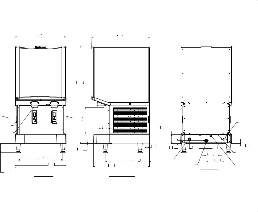
2015 March
3 Page
AIR FLOW
REMOVABLE
AIR FILTER
ICE CHUTE
10.2
4.00 OPTION LEGS ADJUSTABLE
41.3
16.25
WATER CHUTE
34.6
13.62
41.5
16.36
FRONT VIEW
61.9
24.38
88.6
34.88
AIR FLOW
27.9 |
|
|
|
|
11.00 |
|
|
|
|
7.7 |
|
9.7 |
|
|
|
3.80 |
|
|
|
3.02 |
|
UTILITY |
|
|
|
|
CHASE |
|
3 |
|
|
|
|
|
|
|
|
|
1.17 |
0.3 |
|
5.1 |
|
|
.12 |
|
2.01 |
4.6 |
|
|
|
UTILITY |
|
|
|
|
1.80 |
3/8" FLARE |
|
|
|
CHASE |
||
|
|
|
||
36.8 |
10.2 |
8.3 |
3/4" FPT |
WATER INLET |
3.25 |
|
|||
14.50 |
4.00 |
POWER |
DRAIN |
|
59.7 |
|
CORD |
|
|
23.50 |
|
BACK VIEW |
|
|
|
|
|
|
RIGHT SIDE VIEW
HID540 and HID525 HID312,
Manual User’s and Installation
Drawing Cabinet HID312

2015 March
4 Page
54
21.25
AIR FLOW
REMOVABLE
AIR FILTER
ICE CHUTE
WATER CHUTE
|
47.3 |
|
18.62 |
|
54.2 |
|
21.36 |
10.2 |
FRONT VIEW |
4.00 |
OPTION LEGS
ADJUSTABLE
61.9
24.38
88.6
34.88
AIR FLOW
27.9
11.00
|
7.7 |
9.7 |
|
|
3.80 |
|
|
|
3.02 |
|
|
|
UTILITY |
|
|
|
|
|
|
|
|
CHASE |
|
0.3 |
|
5.1 |
|
|
2.01 |
3 |
|
.12 |
|
UTILITY |
1.17 |
CHASE
36.810.2
14.50 |
4.00 |
POWER |
|
|
CORD
59.7
23.50
RIGHT SIDE VIEW
17.85.1
7.002.00
|
12.5 |
|
4.94 |
3/4" FPT |
18.9 |
DRAIN |
7.45 |
BACK VIEW
HID540 and HID525 HID312,
Manual User’s and Installation
Drawing Cabinet HID525
1/2 FPT CONDENSER DRAIN
(WC ONLY)
4.6
1.80
3/8 FPT CONDENSER WATER INLET (WC ONLY)
3/8" FLARE WATER INLET
54 |
61.9 |
|
21.25 |
||
24.38 |
||
|
2015 March
5 Page
AIR FLOW
REMOVABLE
AIR FILTER
ICE CHUTE
10.2
4.00 OPTION LEGS ADJUSTABLE
47.3
18.62
54.2
21.36
FRONT VIEW
103.8
40.88
AIR FLOW
27.9
11.00
7.7 |
|
|
9.7 |
|
|
3.02 |
|
|
3.80 |
|
|
|
|
|
UTILITY |
|
|
|
|
|
CHASE |
|
|
0.3 |
|
5.1 |
3 |
17.8 |
5.1 |
|
2.01 |
||||
|
1.17 |
7.00 |
2.00 |
||
.12 |
|
|
|||
|
|
|
|
12.5 |
|
|
|
|
POWER |
|
|
|
|
|
|
4.94 |
|
36.8 |
10.2 |
|
CORD |
|
18.9 |
|
|
3/4" FPT |
|||
14.50 |
4.00 |
|
|
7.45 |
|
59.7 |
|
|
|
DRAIN |
BACK VIEW |
|
|
|
|
||
23.50 |
|
|
|
|
RIGHT SIDE VIEW
HID540 and HID525 HID312,
Manual User’s and Installation
Drawing Cabinet HID540
1/2 FPT CONDENSER DRAIN
(WC ONLY)
4.6
1.80
3/8 FPT CONDENSER WATER INLET (WC ONLY)
3/8" FLARE WATER INLET
HID312, HID525 and HID540
Installation and User’s Manual
Placement
The location of the equipment should be selected with care. Consideration should be given to allow adequate space on the sides for air cooled models to breathe.
Minimum clearances for air cooled models:
•6 inches at each side
•2 inches above, 10” more to allow auger removal when ceiling is fixed.
•6 inches at the back.
Air cooled models flow air left to right. More space than the minimum at the sides will maximize performance.
Cafeteria applications.
The unit can be placed in a cafeteria line for ice and water. As some users sometimes dispense too much ice, high volume use may require the drip tray to be occasionally cleared of spilled ice.
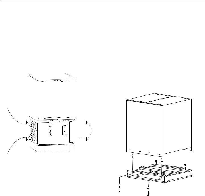
Unpack
1.Separate the carton from the shipping pallet.
2.Remove any strapping holding the cabinet to the pallet.
3.Inspect for hidden shipping damage. If any is found, retain carton and notify carrier for potential claim. Shipping damage is not covered by warranty.
4.Remove bolts holding machine to pallet. Use caution to not tip unit too far when removing bolts.
Airflow Direction
The power outlet should be located within the length of the supplied power cord. If placed on a counter, the counter must be strong enough to support the weight of the unit. Space above the cabinet should be allowed for service and maintenance. If legs will be used, allow space for the total cabinet height.
Air cooled models in a small room will require ventilation to exhaust the heat they produce. They also produce some added noise from the fan.
Noise sensitive areas should consider water cooled equipment or the machine located where the noise from ice making is not objectionable.
Nearby infrared emitters or a window that allows sunlight to shine on a dispensing sensor may cause the unit to dispense ice or water without a container to trigger it.
Unpacking
5.Remove plastic covering the drip tray.
6.Remove the protective plastic covering the panels.
The longer it is left on the panel, the harder it will be to remove it.
7.Place unit on machine stand or on counter. If on machine stand secure the cabinet to the machine stand with the required fasteners.
March 2015
Page 6

HID312, HID525 and HID540
Installation and User’s Manual
Counter Installations
Units placed on a counter must either use legs or be sealed to the counter top with food grade sealant per local codes. To avoid disturbing the seal, complete the installation prior to sealing.
Note: Seal
Chassis to
Counter, do NOT
Seal Drip Tray
Panel Removal
Remove one screw at bottom front of upper front panel, swing bottom of panel forward and lift off the unit.
Legs
4” legs are optional for countertop applications. They are not to be used on the HID dispenser when it is placed on a machine stand.
Note: Use only legs of 4”
minimum height.
Twist ice and water chutes
counterclockwise and pull down to remove.
Remove four screws from sides of lower front panel, pull forward slightly and rest it
on the drip tray. If needed, unplug sensor connector and separate panel from unit.
Set Up
The drip tray and cup rest are shipped in place, there is no need to attach or remove them. It is a good idea to remove the front panels and inspect for any loose or rubbing parts prior to installation.
Pre-Start Inspection
Level the cabinet front to back and left to right. Confirm there are no loose or rubbing parts. Return splash panel and chutes to unit.
March 2015
Page 7
Loading...