


Installation and User Manual for
Prodigy Eclipse Cuber
model EH222 C with ECC Condensing Unit

EH222 and Condensing Unit
Remote Low Side Cuber User Manual
Introduction:
This manual covers the assembly, installation, start up, operation and maintenance of the 800 and 1000 remote low side cuber systems.
Contents |
|
|
|
Configuration. |
|
Page |
3 |
Specifications and Location Information. . . . . . . . . . . . . . . . . . . . . |
. |
Page |
4 |
Cabinet Drawings, Ice Making Head . |
|
Page |
5 |
Cabinet Drawings, Condensing Unit. . . . . . . . . . . . . . . . . . . . . . . . . . . . . . . . . |
. |
Page |
6 |
Pre-Installation Details. . . . . . . . . . . . . . . . . . . . . . . . . . . . . . . . . . . . . . . . |
. |
Page |
7 |
Create the System. . . . . . . . . . . . . . . . . . . . . . . . . . . . . |
|
Page |
8 |
Completed System Example . |
|
Page |
9 |
Place Remote System. . . . . . . . . . . . . . . . . . . . . . . . . . . |
. |
Page |
10 |
Tubing. . . . . . . . . . . . . . . . . . . . . . . . . . . . . . . . . |
|
Page |
11 |
Place Ice Making Head. |
|
Page |
12 |
Drain Connections. . . . . . . . . . . . . . . . . . . . . . . . . . . . . |
|
Page |
13 |
Water Supply: . . . . . . . . . . . . . . . . . . . . . . . . . . . . . . |
. |
Page |
14 |
Electrical:. |
|
Page |
15 |
Connect Refrigeration. . . . . . . . . . . . . . . . . . . . . . . . . . . |
. |
Page |
16 |
Complete the Installation. |
|
Page |
17 |
Reference for Start Up: Controller Operation . . . . . . . . . . . . . . . . . . . |
. |
Page |
18 |
Initial Start Up. . . . . . . . . . . . . . . . . . . . . . . . . . . . . . |
. |
Page |
19 |
Ice Thickness and Water Purge Adjustment. . . . . . . . . . . . . . . . . . . . |
|
. Page |
20 |
Adjustable Ice Level Control. . . . . . . . . . . . . . . . . . . . . . . . . |
. |
Page |
21 |
Cleaning, Sanitation and Maintenance. |
|
Page |
22 |
Operational Characteristics 800 lb system. |
|
Page |
24 |
Operational Characteristics 1000 lb system. . . . . . . . . . . . . . . . . . . . |
|
. Page |
24 |
What to do before calling for service: . . . . . . . . . . . . . . . . . . . . . . |
. |
Page |
25 |
EH222 Schematic Diagram . . . . . . . . . . . . . . . . . . . . . . . . . |
. |
Page |
26 |
EH222 Wiring Diagram. |
|
Page |
27 |
ECC Three Phase Schematic Diagram . . . . . . . . . . . . . . . . . . . . . |
. |
Page |
28 |
ECC Three Phase Wiring Diagram. |
|
Page |
29 |
ECC Single Phase Schematic Diagram. . . . . . . . . . . . . . . . . . . . . |
. |
Page |
30 |
ECC Single Phase Wiring Diagram. . . . . . . . . . . . . . . . . . . . . . . |
|
Page |
31 |
March 2013
Page 2
EH222 and Condensing Unit
Remote Low Side Cuber User Manual
Configuration
A remote low side cuber system includes two sub systems: an ice making head and a remote air cooled condensing unit. This manual covers the EH222 head and the condensing units that go with it.
The ice making heads are designed for use indoors in a controlled environment. The remote condensing units are designed to operate outdoors. Each subsystem has limits for power, water and temperature.
Operational Limitations:
|
Minimum |
Maximum |
Air Temp (at head) |
50oF |
100oF. |
Air Temp (CU) |
-20oF. |
120oF. |
Water Temp |
40oF. |
100oF. |
Water Pressure |
20 psi |
80 psi |
Water Conductivity |
10 microSiemens/cm |
any |
Voltage (at head) |
104 |
126 |
Voltage (CU) |
198 |
253 |
CU= Condensing Unit
Do Not operate the machine in conditions beyond these limitations. Doing so will void the warranty.
Warranty
Refer to the warranty coverage in effect when the equipment was sold. Warranty statements are included with each product.
Systems:
Ice making heads and condensing units have their own model and serial numbers. They must be combined to create a remote cuber low side system.
Notes: Voltage Codes are at the end of the model number. Codes read Voltage/Hertz/Phase. Those related to these products include:
-1 = 115/60/1
-3 = 208-230/60/3
-32 = 208-230/60/1
System Information
Tubing kits are required to connect the head to the condensing unit.
Interconnecting 24 volt control wire ships with the condensing unit.
System Size |
Condensing Unit (CU) |
Ice Making Head |
||
|
Model |
Electrical (volts/Hz/phase |
Model |
Electrical (volts/Hz/phase) |
800 |
ECC0800-32A |
208-230/60/1 |
EH222SL-1C |
115/60/1 |
800 |
ECC0800-3A |
208-230/60/3 |
same |
same |
1000 |
ECC1410-32A |
208-230/60/1 |
same |
same |
1000 |
ECC1410-3A |
208-230/60/3 |
same |
same |
Scotsman ice systems are designed and manufactured with the highest regard for safety and performance. They meet or exceed common agency standards.
Scotsman assumes no liability of responsibility of any kind for products manufactured by Scotsman that have been altered in any way, including the use of any part and/or other components not specifically approved by Scotsman.
Scotsman reserves the right to make design changes and/or improvements at any time. Specifications and design are subject to change without notice.
March 2013
Page 3

EH222 and Condensing Unit
Remote Low Side Cuber User Manual
Specifications and Location Information
Model |
Electrical |
Minimum |
Maximum |
System Charge, |
Cabinet Size* |
Unit Weight |
|
|
volts/Hz/phase |
Circuit |
Fuse Size |
oz of R-404A |
w” x d” x h” |
(lb) |
|
|
|
Ampacity |
|
|
|
|
|
EH222SL-1C |
115/60/1 |
1.13 |
15 |
|
shipped w/none |
22 x 16.5 x 29 |
90 |
ECC0800-32 |
208-230/60/1 |
14.8 |
20 |
|
192 |
32 x 39 x 39.75 |
|
ECC0800-3 |
208-230/60/3 |
10.6 |
15 |
|
192 |
32 x 39 x 39.75 |
|
ECC1410-32 |
208-230/60/1 |
14.5 |
30 |
|
224 |
32 x 39 x 39.75 |
|
ECC1410-3 |
208-230/60/3 |
9.1 |
20 |
|
224 |
32 x 39 x 39.75 |
|
|
|
|
|
|
|
|
|
|
|
|
|
|
|
|
|
March 2013
Page 4
EH222 and Condensing Unit
Remote Low Side Cuber User Manual
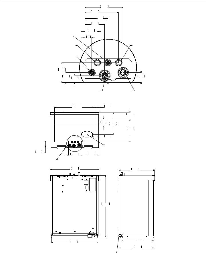
Cabinet Drawings, Ice Making Head
131.70
5.19
115.95
4.57
79.38
3.13
68.20
2.69
|
42.80 |
|
1.69 |
3/8" LIQUID LINE |
24 |
|
|
|
.95 |
ELECTRICAL CORD |
INTERFACE CABLE |
ACCESS HOLE |
|
|
ACCESS HOLE |
1/2" COOL VAPOR LINE
67.56
2.66
34.04 |
24.89 |
34.04 |
|
1.34 |
1.34 |
||
.98 |
|||
|
|
||
|
POTABLE WATER INLET 3/8" |
3/4" SUCTION LINE |
TOP VIEW |
DETAIL A |
|
|
|
|
|
|
482.60 |
47.72 |
|
|
19.00 |
1.88 |
|
|
|
|
|
83.82 |
|
|
|
3.30 |
ICE DROP AREA |
82.55 |
263.65 |
|
|
3.25 |
|
|
|
10.38 |
|
|
|
|
273.05 |
|
|
|
|
|
|
|
|
10.75 |
|
|
|
MINIMUM BIN |
A |
76.20 |
|
TOP OPENING |
|
3.00 |
|
|
ULTRA SONIC
BIN LEVEL
SENSOR
82.55 |
152.40 |
212.85 |
3.25 |
6.008.38
LINE SET, POTABLE WATER INLET 3/8", 120V AC, AND INTERFACE CABLE
SEE DETAIL "A"
581.35
22.89
736.60
29.00
558.80
22.00
REAR VIEW
DRAIN 3/4" PVC FEMALE
REAR, LEFT AND RIGHT SIDE ACCESS
March 2013
Page 5
426.03
16.77
381
15.00
416.74
16.41
LEFT SIDE VIEW
EH222
ICE HEAD
EH222 and Condensing Unit
Remote Low Side Cuber User Manual
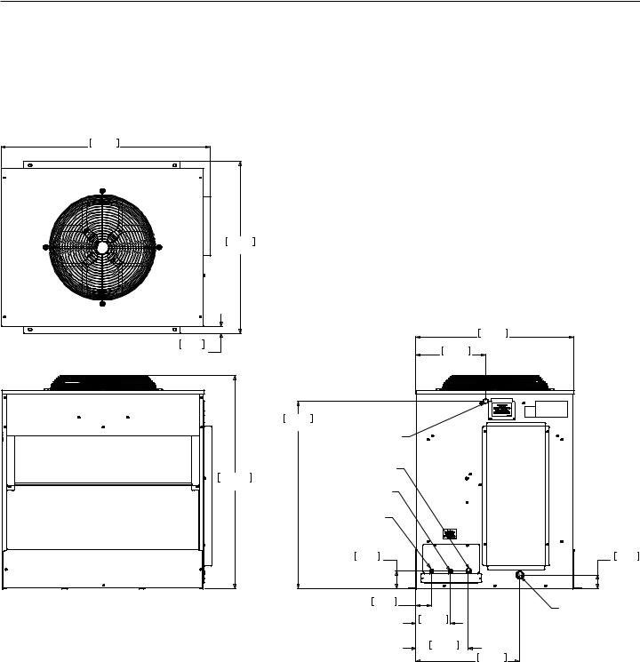
Cabinet Drawings, Condensing Unit
TOP VIEW
992.81
39.09
814.22
32.06
|
32.05 |
|
|
1.26 |
|
FRONT VIEW |
|
TYP. |
|
|
|
|
|
|
1009.65
39.75
SIDE VIEW
LINE SET AND ELECTRICAL ATTACHMENT SIDE
750.06
29.53
330.86
13.03
887.73
34.95
 .88" ELECTRICAL INLET
3/4" SUCTION LINE
1/2" COOL VAPOR LINE
3/8" LIQUID LINE
83.67 |
|
63.50 |
3.29 |
|
2.50 |
74.12 |
|
INTERFACE HARNESS |
2.92 |
|
|
|
163.02 |
ACCESS HOLE |
|
|
|
|
6.42 |
|
248.87
9.80491.69
19.36
March 2013
Page 6
EH222 and Condensing Unit
Remote Low Side Cuber User Manual
Pre-Installation Details
Note: The ice making section cannot be stacked vertically.
Accessories such as bin adapters and tubing kits are required to complete the installation.
Dispenser Adapter Kits:
•Cornelius ABS: KBTABS ED150: KBT40
•Scotsman ID150: KBT40
•Scotsman ID200 or ID250: KBT41
Bin Adapter Kits:
•B530P or B530S: KBT32
•B948S: KBT34
Tubing Kits:
•20 foot: 3BRTE20-EH
•35 foot: 3BRTE35-EH
•50 foot: 3BRTE50-EH
•75 foot: 3BRTE75-EH
Note: Line set may have quick connects. The condensing section may have quick connects. See refrigeration system detailed instructions connection details.
Items required for installation:
•Ice making head
•Condensing unit (includes interconnecting control system wire)
•Tubing kit. 20’, 35', 50’ or 75’ triple line set (liquid, vapor and suction)
•Bin or dispenser adapter
Special Considerations
The ice making section’s footprint is 22” wide by 16.5” deep. The refrigeration connections can be routed up or to the back. The drain may be routed out the back at any position left to right; it may also be routed to either side.
Water
Pure water does not exist. All water supplies contain some amounts of impurities, although potable water is, by definition, fit for human consumption. Because the contents of the water to an ice machine directly impact its performance, consideration should be given to improving the water’s quality.
There are two ways water can contain impurities: in suspension or in solution. Suspended solids can be filtered out of the water. In solution or dissolved solids must be diluted or treated. Water filters are recommended to remove the suspended solids.
Some filters or filter systems have treatment chemicals in them for treating the suspended solids.
This ice machine has an adjustment for the amount of water rinsed or purged. Water use adjustments are customer convenience adjustments; they are not factory defects and are not covered by warranty.
March 2013
Page 7

EH222 and Condensing Unit
Remote Low Side Cuber User Manual
Create the System
Plan the installation. The system consists of three parts: the ice making head, the condensing unit and the interconnecting tubing. Of these, the biggest variable is the interconnecting tubing.
Tubing: The tubing consists of three insulated and sealed soft copper tubes. One tube, the liquid line, is 3/8” OD. The vapor tube is ½” OD and the suction tube is ¾” OD. A site inspection will determine what length of tubing is required for the installation.
In 2013 Scotsman made a change to the Eclipse tubing kits:
•Prior Tubing Kits: They each contain a small holding charge of R-404A and have quick connects at the ends.
•Current Tubing Kits: The do not contain any refrigerant and do not have quick connects.
Either type can be used to connect the head and condensing unit.
Check condensing unit for quick connects. If none, recover refrigerant from tubing and cut the quick connects off.
Elevation: Condensing unit limited to 35 feet above the ice making section.
Condensing Unit: Electrical power must be supplied to the condensing unit, it will be separate from the head.
Ice making section location and attachment: The unique footprint of the EH222 requires adapter kits to allow placement on dispensers and bins.
The remote tubing connections are at the top of the machine, and connections should not be made until the machine is nearly in its final installed position.
The 115/60 Hz ice making section is cord connected and requires an outlet within 6 feet of the installation.
Interconnecting wires: An interconnecting wire harness is included with the condensing unit. One end plugs into the ice making section and the other into the condensing unit. The system will NOT operate without this harness.
Exposed tubing: Minimize the amount of tubing exposed outdoors.
Lineset |
Ice machine head and condensing |
Ice machine head has stubs, condensing |
|
unit both have stubs |
unit has quick connects. |
Has Quick Connect Fittings |
Cut quick connects off both ends |
Cut off quick connects at condensing unit |
|
|
end only |
Does NOT have Quick |
Use as supplied |
Use as is at head, obtain kit KTE6-EH, |
Connect Fittings |
|
use 3 of 6 fittings on condensing unit end. |
Excess tubing must be shortened at the job site.
Installations with greater than 20 feet of vertical lift between ice machine and the compressor require a suction line trap. The suction line requires careful handling and large radius bends to prevent kinking.
Roof mounting: Some installations will require the use of a hoist to lift the components to the roof.
Pad mounting: The condensing unit may be located below the ice making section, up to a limit of 15 feet.
Distance from unit: Limited to the length of the available tubing.
March 2013
Page 8

EH222 and Condensing Unit
Remote Low Side Cuber User Manual
Completed System Example
March 2013
Page 9

EH222 and Condensing Unit
Remote Low Side Cuber User Manual
Place Remote System
Roof preparation
Most installations of this system will place the condensing unit on the roof of a building. The roof must be physically able to accept the load of the equipment and the roofing material must be prepared to prevent water leaks.
Follow local codes for the placement and attachment of the equipment.
Location
The condensing unit requires unobstructed air flow to operate efficiently. A four foot space between each intake side and a wall or other cabinet is recommended.
Do not place where it will pick up hot discharged air from an air conditioner or other refrigeration system condensing unit.
Space must also be reserved for service on the condensing unit.
Roof Piercing:
The roof (or wall) must have a passage large enough for the three refrigeration tubes and the control wire to pass through. The minimum recommended size is 4” ID. In most areas the power supply may also pass through the same passage. If there isn’t a passage one must be created. In most cases this must be done by a licensed and bonded roofer in order to maintain the roof’s integrity.
Roof Pipe Curb or Pitch Pocket:
To avoid potential kinking of the refrigeration tubing, avoid small, tight radius types of covers on pitch pockets.
Suggestions:
In most cases a mechanical lift, boom truck or crane will be required to hoist the condensing unit.
Mount unit to roof rails or curbs and secure with lag screws or similar field supplied fasteners.
Orient the assembled unit so that the unit’s mounts are parallel to the pitch of the roof to allow water to drain freely.
Do NOT place the unit directly onto roof rock.
March 2013
Page 10
 Loading...