

Page 1

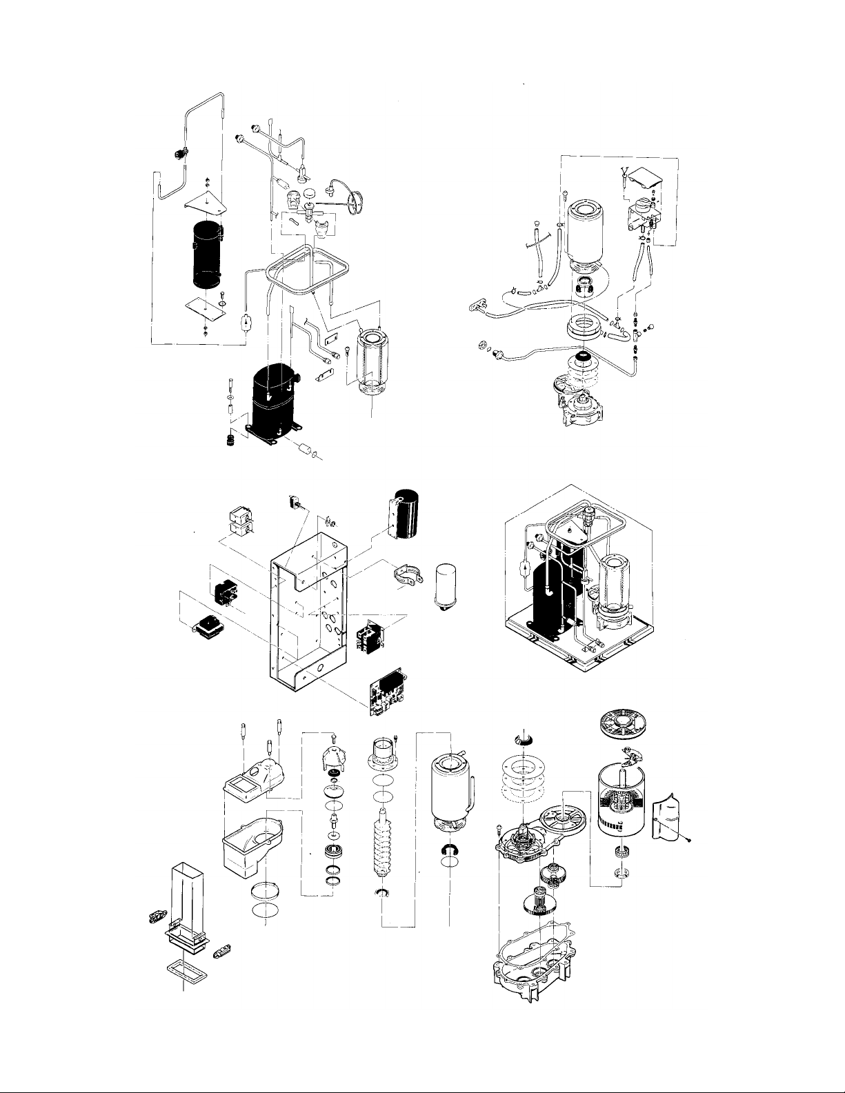
FM1200R SERVICE PARTS
This parts list contains the service parts and
wiring diagrams for this model. Check the model
number in question to be sure that it is applicable
to this parts list.
TABLE OF CONTENTS
Cabinet ..............................................................................2
Refrigeration.......................................................................3
Water .................................................................................4
Gearmotor...........................................................................5
Evaporator..........................................................................6
Control Box.........................................................................7
Remote Condenser............................................................8
Wiring Diagrams.................................................................9
Page 2
FM1200R SERVICE PARTS
October, 1991
Page 1
Page 3
FM1200R SERVICE PARTS
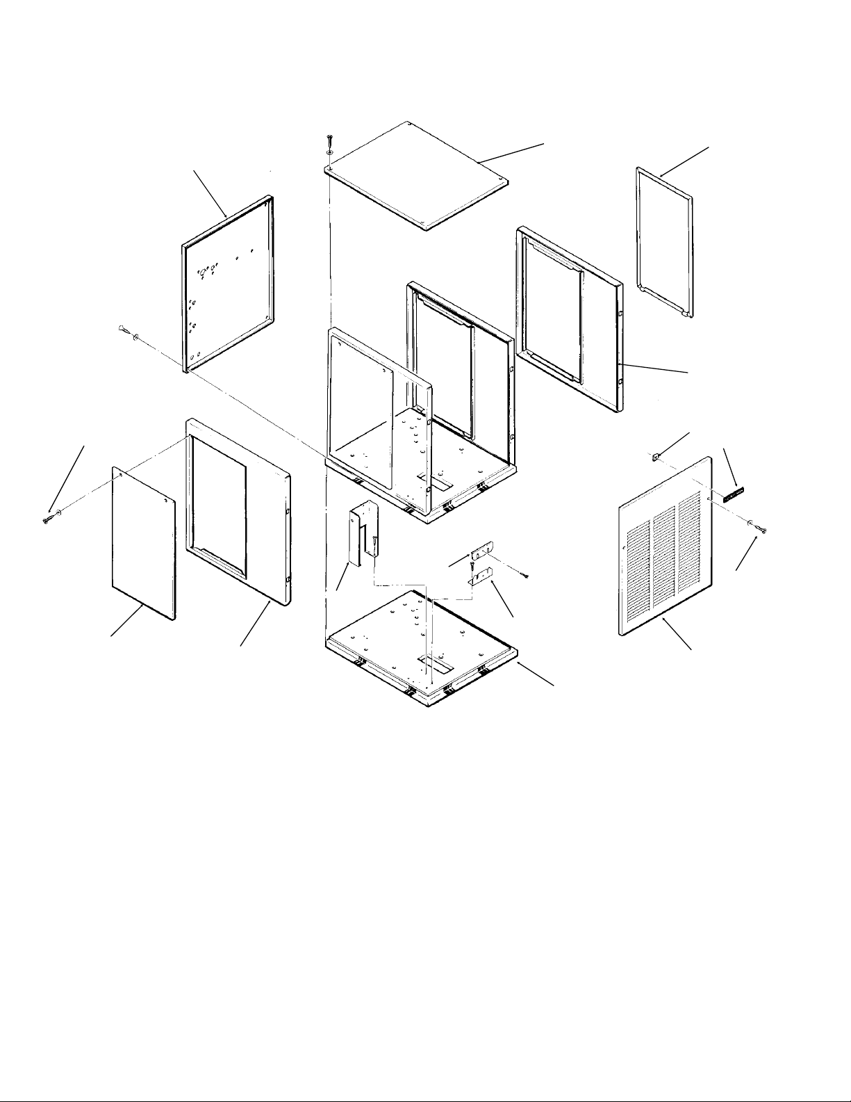
Cabinet Assembly
14
2
1
3
4
5
6
12
3
13
ITEM PART
NUMBER NUMBER DESCRIPTION
1 A33252-001 Back Panel, Painted
2 A33256-001 Top Panel, Painted
A33256-002 Top Panel, S.S.
3 A34038-001 Service Panel, Painted
A34038-002 Service Panel, S.S.
4 A33292-001 Right Side Panel, Painted
A33292-002 Right Side Panel, S.S.
5 03-0271-00 Speed Clip
6 15-0711-01 Emblem
7 03-1419-08 Screw
11
10
8
9
ITEM PART
NUMBER NUMBER DESCRIPTION
8 A33255-001 Front Panel, Painted
A33255-002 Front Panel, S.S.
9 A34042-001 Base Assembly
10 A31462-001 Tube Bracket
11 A31461-001 Tube Bracket
12 A34039-001 Control Box Support
13 A32435-001 Left Side Panel, Painted
A32435-002 Left Side Panel, S.S.
14 03-1404-12 Screw
7
October, 1991
Page 2
Page 4
FM1200R SERVICE PARTS
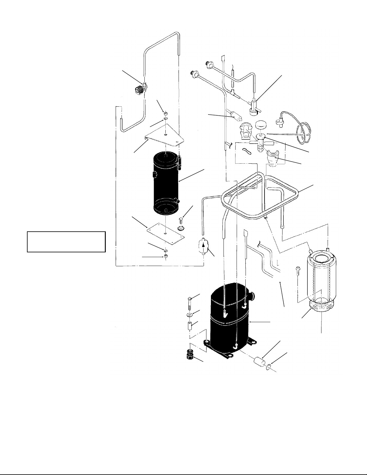
Refrigeration System
NOTE: Compressors
have internal overloads.
1
2
6
3
4
7
8
5
3
14
15
16
17
ITEM PART
2
NUMBER NUMBER DESCRIPTION
1 12-2257-21 Liquid Line Valve
2 03-1406-13 Nut
3 03-1410-06 Washer
4 A32968-001 Receiver Brace
5 A31801-002 Receiver Mount
6 11-0446-23 Hi Pressure Cut Out
7 16-0761-01 Receiver
8 03-1645-01 Cap Screw
9 02-3319-02 Dryer
10 03-1405-20 Cap Screw
11 03-1407-07 Washer
12 18-2300-26 Sleeve
13 18-6800-01 Rubber Grommet
14 11-0422-22 Head Pressure Valve
15 16-0780-21 Thermo Expansion Valve
16 A32961-020 Insulation Kit for TXV
17 A34050-001 Suction Line
18 16-0560-00 Core
16-0563-00 Nut
9
10
11
12
13
20
18
19
21
22
ITEM PART
NUMBER NUMBER DESCRIPTION
19 A32890-020 Evaporator
20 18-8879-21 Compressor (1 Phase)
18-8879-22 Compressor (3 Phase)
21 18-2308-01 Crankcase Heater
22 18-2309-01 Clip
December 2004
Page 3
Page 5
FM1200R SERVICE PARTS
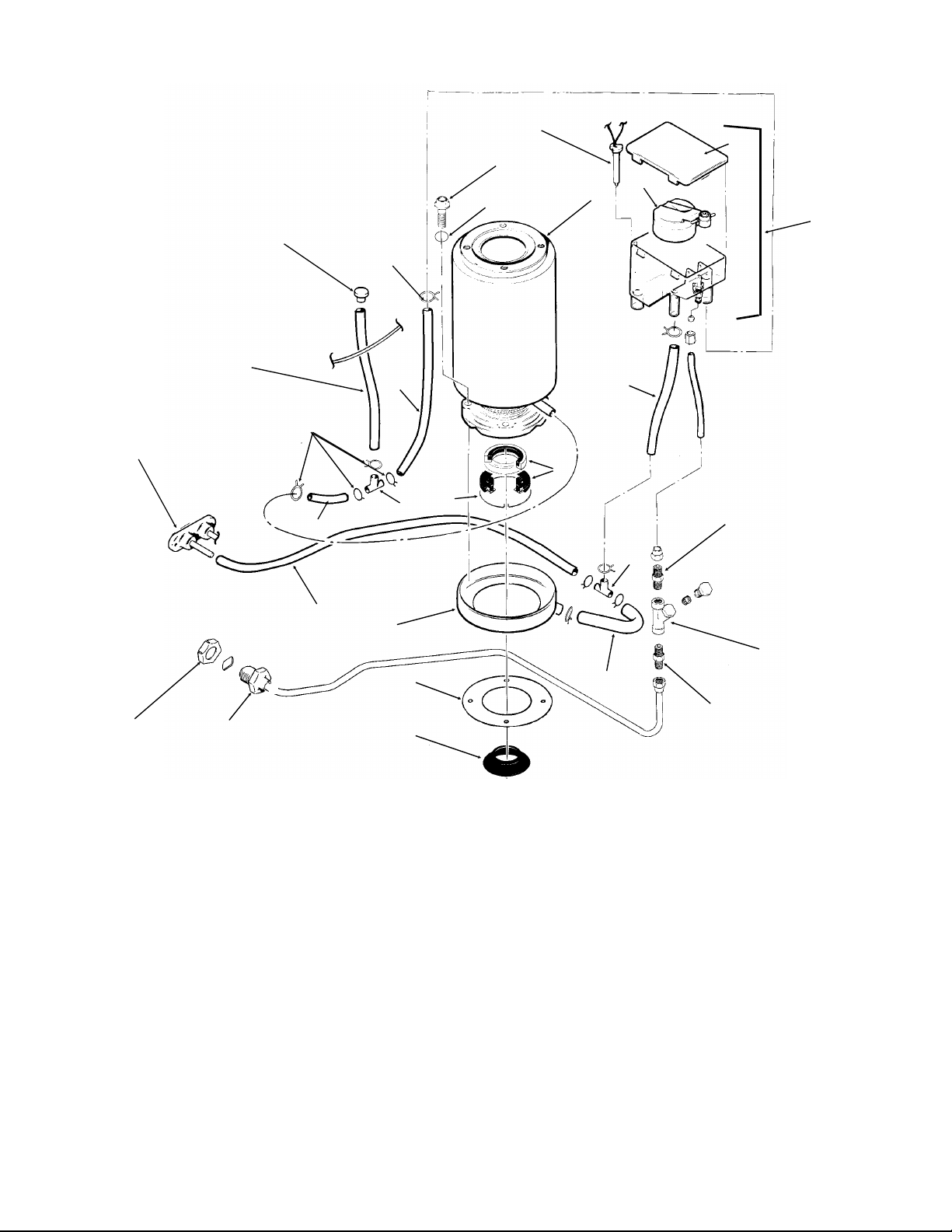
Water System, Water Seal
18
21
22
20
25
20
23
24
2
1
5
27
7
3
17
12
11
4
6
8
16
26
15
14
19
13
ITEM PART
NUMBER NUMBER DESCRIPTION
1 03-1420-03 Cap Screw
2 A33101-022 Water Level Sensor
3 A32890-020 Evaporator
4 02-2936-01 Res. Cover
5 A32907-001 Float Assembly with pin,
housing seal, rubber seat, insert & float
02-3190-01 Rubber seat
6 A32929-020 Reservoir Assembly
7 A32777-001 Retaining Ring for Seal
8 16-0791-01 Half Union
9 16-0162-00 Strainer
10 13-0079-03 Tube, 3.2" req.
11 16-0670-02 Tee
12 02-0929-23 Water Seal
13 13-0868-01 Water Shed
9
10
8
ITEM PART
NUMBER NUMBER DESCRIPTION
14 A32050-001 Drip Pan
15 A27318-001 Water Inlet Fitting
16 03-1394-01 Pal Nut
17 13-0079-03 Res. Overflow, 8" req.
18 A34045-001 Drain Casting
19 13-0704-00 Gasket
20 02-2814-08 Clamps
21 13-0674-06 Evap. Drain, 14" req.
22 A33205-001 Plug
23 13-0674-06 Evap. Inlet Tube, 5" req.
24 16-0670-01 Tee
25 A33203-001 Tube, Preformed
26 13-0079-03 Drain Tube, 24" req.
27. 03-1417-13 Lockwasher
December 2004
Page 4
Page 6

FM1200R SERVICE PARTS
Gearmotor
1
2
*Note: Gearcase
Cover includes:
cover, output
shaft, key,
output gear, &
bearings
4
12
5
6
13
10
11
15
14
7
ITEM PART
NUMBER NUMBER DESCRIPTION
1 13-0868-01 Water Shed
2 A32379-029 Seal
8
4 A32379-026 Bolt
5 A32379-022 Gearcase Cover*
6 A32379-024 1st Gear and Bearings
7 A32379-023 2nd Gear and Bearings
8 A32379-021 Gasket
9 A32379-020 Gearcase
10 A32898-020 Centrifugal Sw, GE PSC
12-2430-24 Start switch, Emerson
9
12-2430-44 Start sw, GE split phase
11 12-2430-22 Drive Motor-230v
12 12-1741-29 Rotor Bearing, GE PSC
12-2430-29 Rotor bearing, Emerson
12-2430-49 Rotor bearing, GE split phase
13 A32379-028 Seal
14 A32379-027 Oil, 1 Container
15 12-2314-22 Capacitor, GE PSC only
16 A33220-022 Complete Assembly 230v
A33220-030 Gears, oil & cases. No motor.
November 2003
Page 5
Page 7

Note: Bail clamp,
pn A34969-001
used beginning in
Jan. 91
FM1200R SERVICE PARTS
Evaporator, Bin Controls
1
2
3
4
5
6
11
10
26
4
12
13
14
15
27
7
17
8
33
9
ITEM PART
NUMBER NUMBER DESCRIPTION
1. 02-2933-01 Hex Stud
2. A32891-020 Switch Assembly
13-0617-53 O-ring
12-2398-01 Man. reset switch
3. 02-2930-01 Ice Chute Cover
4. A32963-001 Insulation Top (half)
5. 02-2926-01 Ice Chute Body
6. A33102-001 Insulation Collar Inside
A35419-020 Strap kit
7. 02-2929-01 Ice Chute Lower
8. A37708-021 Ice level sensors (set of 2)
9. A32930-001 Chute Gasket
10. 03-1405-52 Hex Cap Screw
11. 02-3001-01 Ice Sweep
12. 13-0871-01 Water Shed
13. 02-2978-01 Lip Seal
14. 02-3128-20 Breaker Cover
15. 13-0617-54 O-Ring
16. 08-0660-01 Auger Stud & washer
17. part of item 16
18. A34559-020 Bearing
19. 02-2977-01 Lip Seal
18
22
24
19
8
16
28
29
29
20
30
21
25
23
31
32
20. 03-1405-27 Screw
21. 13-0617-52 O-Ring
22. 02-2916-01 Slotted Collar
23. 13-0617-45 O-Ring
24. 03-1544-08 Soc. Head Screw
25. A34505-020 Breaker (Divider)
(includes 18 & 19)
26. A38071-022 Auger
27. A32890-020 Evaporator
28. 03-1420-03 Cap Screw
29. A32962-001 Insulation Bot. (half)
A32962-002 Insulation (half)
30. A32050-001 Drip Pan
31. 13-0704-00 Drip Pan Gasket
32. A31340-001 Water Shed
33 13-0617-49 O-ring
December 2004
Page 6
Page 8
10
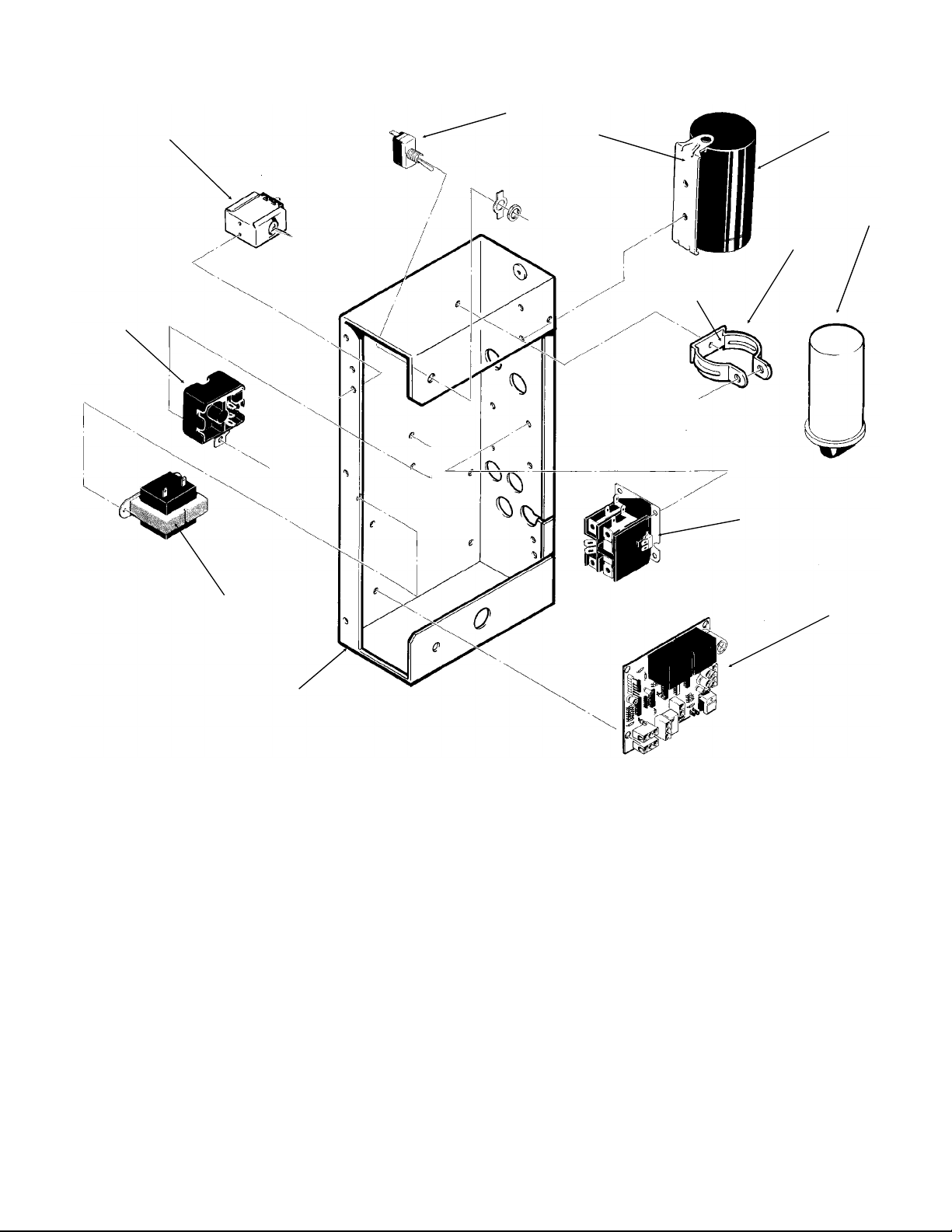
FM1200R SERVICE PARTS
Control Box
8
9
2
4
1
5
3
11
12
ITEM PART
NUMBER NUMBER DESCRIPTION
1 18-1901-48 Start Capacitor
18-4300-50 Start Capacitor Cap.
2. 18-2200-39 Start Capacitor Bracket
03-1638-04 Screw
03-1417-15 Lockwasher
3. A32872-001 Run Cap Bracket
03-1652-02 Bolt
03-0255-04 Wing Nut
4. 03-1638-03 Screw
5. 18-1902-45 Run Capacitor
6. 12-2469-03 Single Phase Contactor
12-0739-02 Three Phase Contactor
6
7
ITEM PART
NUMBER NUMBER DESCRIPTION
7 A32976-020 Circuit Board
8. 12-0426-01 Master Switch
9. 11-0420-23 Pump Down Control
10 18-1903-46 Potential Relay
11. 12-2285-22 Transformer
12 no number Control Box Assy
NOT ILLUSTRATED
13. 12-2337-02 3 Pin Plug Assy
(Safety Circuit to Circuit Board)
14. 12-2340-01 4 Pin Plug Assy
(Transformer to Circuit Board)
15. A34055-001 Control box cover
December 2004
Page 7
Page 9

FM1200R SERVICE PARTS
REMOTE CONDENSER
RC1451-32B or
RC1051-32A or RC1052-32A
ITEM PART
NUMBER NUMBER DESCRIPTION
1. 02-2628-01 Fan Guard
2. 18-6304-01 Fan Blade
3. 18-5301-01 Fan Motor
RC651-32B or RC652-32B
ITEM PART
NUMBER NUMBER DESCRIPTION
1. 02-2618-01 Fan Guard
2. 18-3733-01 Fan Blade
3. 18-5301-01 Fan Motor
October, 1991
Page 8
Page 10

FM1200R SERVICE PARTS
Wiring Diagram, 208-230/60/1
October, 1991
Page 9
Page 11

FM1200R SERVICE PARTS
Schematic Diagram, 208-230/60/1
USE COPPER CONDUCTORS ONLY THIS UNIT MUST BE GROUNDED
All Controls Shown in Normal Ice Making Mode.
Note: Dashed lines indicate field wiring which must be installed in accordance with the National Electric
Code Using a Minimum of 14 ga. awg. wire.
October, 1991
Page 10
Page 12

FM1200R SERVICE PARTS
Wiring Diagram, 208-230/60/3
October, 1991
Page 11
Page 13

FM1200R SERVICE PARTS
Schematic Diagram, 208-230/60/3
USE COPPER CONDUCTORS ONLY THIS UNIT MUST BE GROUNDED
All Controls Shown in Normal Ice Making Mode.
Note: Dashed lines indicate field wiring which must be installed in accordance with the National Electric
Code Using a Minimum of 14 ga. awg. wire.
October, 1991
Page 12
 Loading...