

Page 1

TDE470 Service Manual
TDE470
Purpose of this ma nu al: To provide de ta iled
installation and operation instructions; to give
insights into how the machine works; to list
possible cause s for problems; and to suggest
procedures for s pecific type s of service .
The TDE470 is an ice make r an d dispe nse r
combined into one cabinet. The refrigeration
system is air cooled, using R-134 a as a refrig era nt.
The control system uses elec tric ey es as a bin
control and a water leve l sensor as the water
safety control. As ice is made, it fills a pla st ic
storage bin. When ice is needed , a motor rot at es a
stainless stee l van e inside th e storage bin and
sweeps the ice int o the spo ut .
Table of Contents
Specifications: . . . . . . . . . . . . . . . . . . . . . . . . . . . . . . . . . . . . . . . . . . . Page 2
To The Installer: . . . . . . . . . . . . . . . . . . . . . . . . . . . . . . . . . . . . . . . . . . . Page 3
For The Electrician . . . . . . . . . . . . . . . . . . . . . . . . . . . . . . . . . . . . . . . . . Page 4
For The Plumbe r . . . . . . . . . . . . . . . . . . . . . . . . . . . . . . . . . . . . . . . . . . Page 5
Optional Kits: . . . . . . . . . . . . . . . . . . . . . . . . . . . . . . . . . . . . . . . . . . . . Page 6
Wall Mount Kit (KWB1): . . . . . . . . . . . . . . . . . . . . . . . . . . . . . . . . . . . . . . Page 7
Final Check List & Initial Start Up . . . . . . . . . . . . . . . . . . . . . . . . . . . . . . . . . Page 8
User Operation . . . . . . . . . . . . . . . . . . . . . . . . . . . . . . . . . . . . . . . . . . . Page 9
Component Loca tio n & Functio n . . . . . . . . . . . . . . . . . . . . . . . . . . . . . . . . . . Page 10
Refrigerat ion Syst em Op era tion . . . . . . . . . . . . . . . . . . . . . . . . . . . . . . . . . . Page 11
Water System Operation: . . . . . . . . . . . . . . . . . . . . . . . . . . . . . . . . . . . . . . Page 12
Mechanical Operation . . . . . . . . . . . . . . . . . . . . . . . . . . . . . . . . . . . . . . . Page 13
Electrical Sequence . . . . . . . . . . . . . . . . . . . . . . . . . . . . . . . . . . . . . . . . Page 14
Maintenance: . . . . . . . . . . . . . . . . . . . . . . . . . . . . . . . . . . . . . . . . . . . . Page 15
Dispense Area Sanitation . . . . . . . . . . . . . . . . . . . . . . . . . . . . . . . . . . . . . Page 16
Auger and Bearing Inspection . . . . . . . . . . . . . . . . . . . . . . . . . . . . . . . . . . . Page 17
Inspection: A ug er . . . . . . . . . . . . . . . . . . . . . . . . . . . . . . . . . . . . . . . . . . Page 18
Service Diagnosis . . . . . . . . . . . . . . . . . . . . . . . . . . . . . . . . . . . . . . . . . Page 20
Service Diagnosis: Circu it Board . . . . . . . . . . . . . . . . . . . . . . . . . . . . . . . . . . Page 22
Electrical System . . . . . . . . . . . . . . . . . . . . . . . . . . . . . . . . . . . . . . . . . . Page 23
Removal and Replacement . . . . . . . . . . . . . . . . . . . . . . . . . . . . . . . . . . . . Page 24
Water System . . . . . . . . . . . . . . . . . . . . . . . . . . . . . . . . . . . . . . . . . . . . Page 25
Bearings, Water S eal an d Aug er . . . . . . . . . . . . . . . . . . . . . . . . . . . . . . . . . . Page 26
Bearing Replac ement: . . . . . . . . . . . . . . . . . . . . . . . . . . . . . . . . . . . . . . . Page 27
Refrigerat ion Syst em . . . . . . . . . . . . . . . . . . . . . . . . . . . . . . . . . . . . . . . . Page 28
Gear Reducer Remo val . . . . . . . . . . . . . . . . . . . . . . . . . . . . . . . . . . . . . . Page 29
Auger Drive Motor . . . . . . . . . . . . . . . . . . . . . . . . . . . . . . . . . . . . . . . . . Page 30
A Parts List and Wiring Diagram are located in the center of this m anual, on yellow paper.
February 1995
Page 1
Page 2

TDE470
Specifications:
The standard finish for this machine is painted
enamel. A stainless ste el p anel kit may be inst alle d
at the field leve l to chang e the fin ish to stainless
steel. The kit numbe r is : SPKFD4 70
Scotsman ice machines, like the TDE4 70 , are
designed to be installe d ind oors, in a controlle d
environment. The minimum a nd maximu m
operatin g cond itio ns are:
••Minimum Air Temperature: 50
••Maximum Air Temperatu re: 100
••Minimum Water Temperature: 40
•• Maximum Water Temperature: 100
o
F.
o
F.
o
F.
o
F.
••60 Hz voltage may vary betwee n 104 and 126
volts.
••Water Pressu re may va ry between 20 and 80
psi.
Operatin g the mac hin e ou tsid e thes e con dit ions
constitu tes misuse and voids the warrant y.
Scotsman Ice Systems are designed and
manufactured with the highest regard for safety
and performance . They meet or ex cee d the
standards of UL, NSF and CUL.
Scotsman assu mes no liability or res po nsib ility of
any kind for pro duct s ma nufa ct ured by Scotsman
that have been altered in any way, including the
use of parts and/of other components not
specifically approved by Scotsman.
Scotsman reserves the right to make design
changes and/or improvements at any time.
Specifications and designs are subject to change
without notice.
Model Number Dimensions
W" x D" x H"
TDE470AE-1A
TDE470AE-6A
14 x 23
14 x 23
3
⁄4 x 277⁄
3
⁄4 x 277⁄
Basic
Electrical
115/60/1 12 lb. 470 lb./24Hr 14 oz. 14.6 20
8
230/50/1 12 lb. 14 oz. n/a n/a
8
Bin
Capacity
February 1995
Ice Making
Capacity
Page 2
Refrigera nt
Charge
(R134a)
Min.
Circuit
Ampacity
Max
Fuse Size
Page 3
To The Installer:
TDE470
A pro fe ssio na l insta llat ion of any produ ct is critic al
to the long term satisfaction of the user. The
TDE470 is designed to be installed either on a
counter, or, usin g a wall hanging kit, hung from a
wall. Another opt ion is a kit to increa se the ca bin et
height which will allow taller containers to be
placed under the spout. Determine the location
from the anticip ated use and any optio ns plann ed
for.
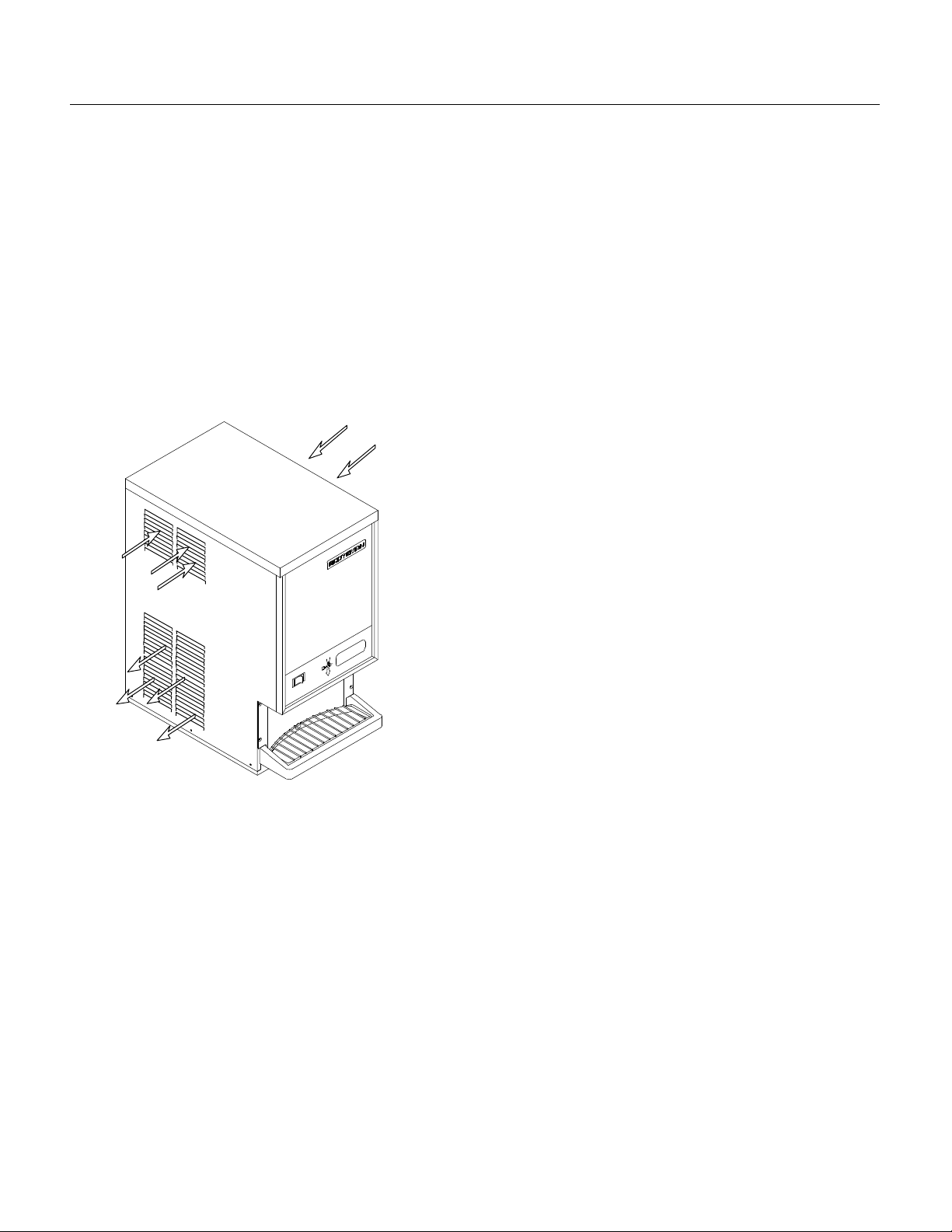
This machine is air cooled and blows air out the
lower left side of the cabinet. Do not install the
machine whe re the side to side air flo w might be
blocked.
Cooling Air Flow
Cooling
Air Flow
Water Quality:
The quality of the water supplie d to the mach ine
will directly affe ct th e purity of the ice and the
reliability of the machin e. While th e condit ion of the
water supplied to a building is normally ou t of the
control of the user, wate r can be trea te d at the
point of use.
There are two major typ es of water impurities:
suspended solids (those that are carried along
with the water and may be filtered out) and
dissolved solids (those that are part of the wate r
and have to be treated). A wate r filt er is alwa ys a
good idea, but does require regular maint enan ce
to change the cartridg e. In some wat er condit ions,
water treat men t may be require d. Genera lly this
means a polyphosphate feeder of some kind.
Water sof te ners are not rec omme nd ed for the
TDE470.
General Installation:
Place the machin e in its fina l location. Remo ve the
top, right and left side panels:
1. Remove two screws at the bac k of the top panel.
2. Pull up on the back of the top panel and remove
it.
Warm Air
Exhaust
The machine will require electrical power, water
and a drain. Follow all loc al codes . Rou gh in the
utilities befo re pla cing the mach ine into posit ion
(see For The Electrician and For The Plumbe r).
3. Remove screws from the sides (to p and bottom)
of the side panels an d fro m the spla sh pa ne l.
4. Pull the side panels back and of f the machin e.
Plumbing co nnections may be ma de thru hole s in
the ba c k of the c abine t or thru th e base.
••Route the sink drain to the back of th e cabinet.
Route the bin drain to the back panel.
••Route the electrical power cord from the
junction box inside the cabinet. thru the back
panel .
••Route the inlet water line thru the back panel or
base to the fla re fit ting inside the cabin et .
Install the sta inle ss steel panel kit (if us ed) n ow.
Install the back pa nel o f the sta inle ss steel panel
kit now (if used).
After all plumbing and interna l wiring has been
done, replac e th e side and bac k panels .
Level the unit front to back and left to right.
The machine does not require sealing to the
counter due to the gasket on the base.
February 1995
Page 3
Page 4
TDE470
For The Electrician
Electrical conn ection s:
Check the nameplat e for v olt age and curre nt
requiremen ts . An ele ct rical c ord is not supplie d.
Connect the TDE470 to a separate electrical
circuit. Wiring to the machin e must confo rm to all
codes. A licensed electrician may be required in
some situations.
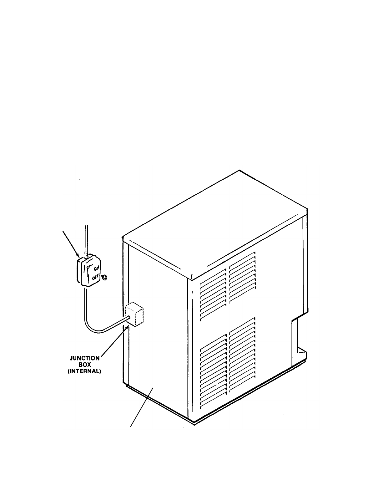
Remove the back panel to make the ele ct rical
connection . The electrical connectio n is made on
the terminal strip in the junction box inside the
machine. Replace the back panel when the
electrical conn ect ions are complete.
FOLLOW ALL APPLICABLE LOCAL,
STATE AND NATIONAL CODES
This Unit MUST BE GROUNDED
Electrical
Power
Remove Back Panel To
Expose Junction Box
February 1995
Page 4
Page 5
For The Plumber
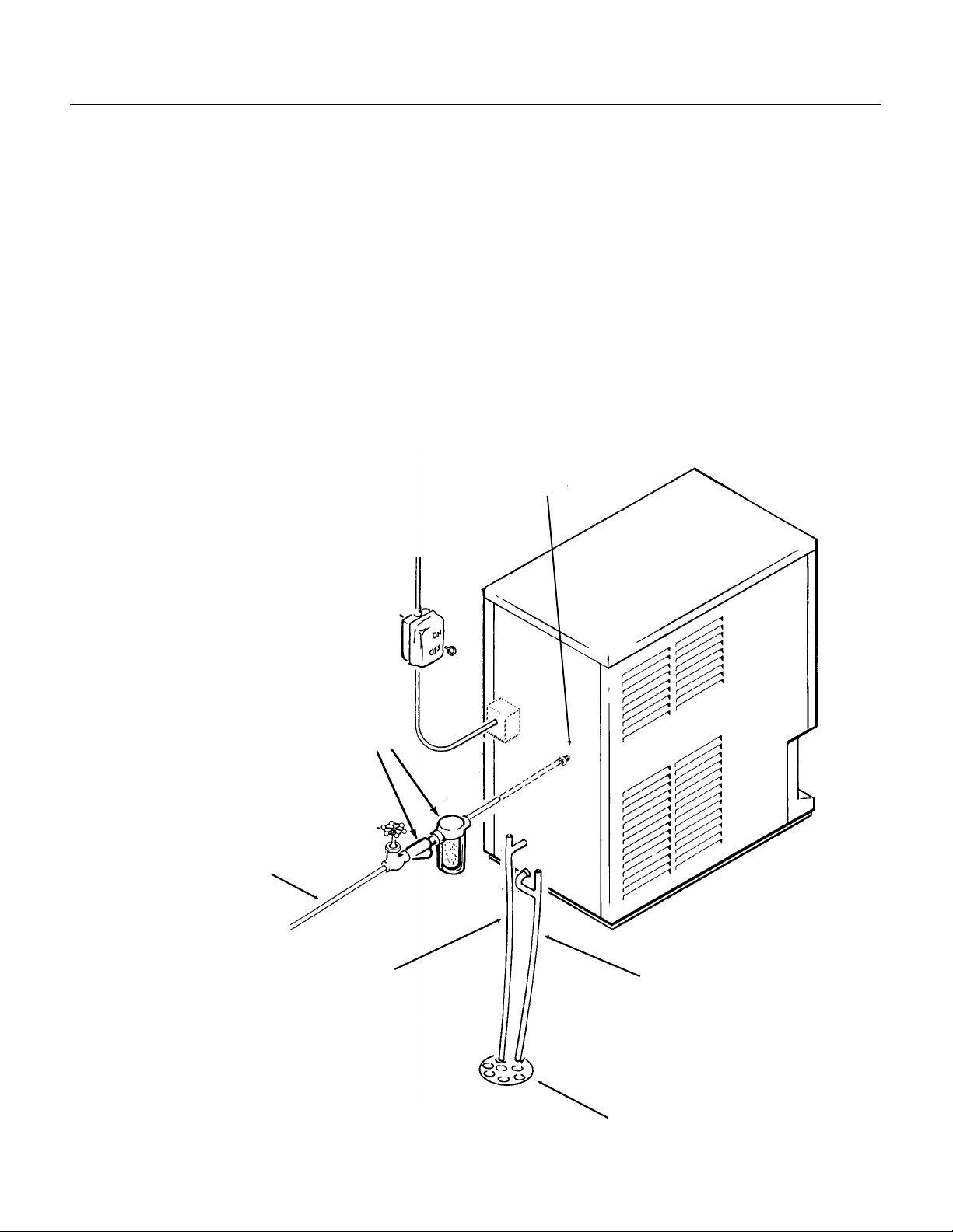
Drains:
The dispenser req uire s a gravity drain. The pitch
on the drain tubes must be at least 1/4 inch fall per
foot of horizont al run . On long horizo ntal runs, a
vent at the back of the cabinet will improve
draining, and is recommended.
There are two dra ins to connect : A sin k dra in, a
plastic tube; and the bin drain, a
5
⁄8" plastic tube.
Install rigid tubing bet wee n the mach ine and the
building drain. Rout e the dra ins sepa rat ely to the
building drain.
7
⁄8"
TDE470
Water supply:
Connect cold, pota ble wate r to the machine. A
hand valve ne ar th e lo ca tio n is recomme nded . A
water filter is also a good idea.
Follow all local codes.
Strainer or
Filter
FOLLOW ALL APPLICABLE LOCAL,
STATE AND NATIONAL CODES
Water Inlet Fitting
(Inside Cabinet)
Water Supply
Bin and
Reservoir
Overflow Drains
Sink Drain
Building Drain
(Typical)
February 1995
Page 5
Page 6
TDE470
Optional Kits:
Sink Exten sio n (KDE 1A ename l or K DE1 A-SS
stainless steel):
If installe d, follo w the se st ep s, if no t go to st ep 2.
••A. Unplug or disconnect electrical powe r.
••B. Remove top and right side panels .
••C. Shut off water supply and dis con nect wate r
inlet tube.
•• D. Drain reservoir.
2. Unplug or disconnect electrical power. Remove
splash panel from the dispenser’s cabinet. Save
the screws for re-assemb ly.
3. Remove the Touch-Free sensor from the spla sh
panel. Save the hard ware for re-a sse mbly.
4. Loosen hose clamp at sink drain.
5. Remove screws holding sink to dispenser
cabinet.
6. Remove the original sink from the cabin et .
7. Carefully lay the dispenser on its left side.
8. Remove the gasket from the base of the
dispenser.
16. Cente r and att ach the ice deca l on spla sh
pane l wi t h the op ening ov er the
portion of the sensor holder.
17. Install spla sh pan el to the dispe ns er cab ine t
with 4 sheet metal screws (from step 2).
18. Place the warnin g stic ker abou t 2
ice decal.
19. Install grill.
20. Pour water in sin k and check fo r drain ag e or
leaks.
21. Replace all panels, and recon nect any ut ilitie s.
1
⁄2" x 1 1⁄2" raised
1
⁄2" lef t of the
9. Place the sink extension base against the
bottom of the d is pen se r. The fla nge of the
dispenser base fits in the
slots in the sink ext en sion
base.
10. Secure the sink
extensio n ba se to th e
dispenser with 3 screws on
each side.
11. Ret urn the dispe ns er to
an upright position.
12. Attach t he d rain fitting,
drain top and o-ring (o-ring
goes under the sink) to the
sink from the kit.
13. Place the new sink and
drain on the dispenser.
Attach sink drain tube and
secure with a hose clamp.
14. Secure sink to cabine t
with 2 machine screws.
15. Install sen so r hold er in
new splash panel using
hardware saved in step 3.
February 1995
Page 6
Page 7
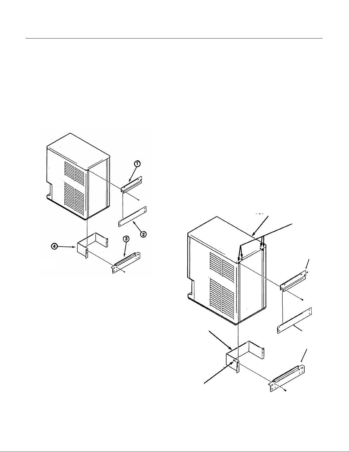
Wall Mount Kit (KWB 1):
Wall
Brackets
TDE470
Contents:
1. Top Case Hanger Brac ket : A tt ac he s to th e f rame
of th e dispenser.
2. Top Wall Bracket: Mounts to the wall an d
enga ges th e top cas e hang er br acke t to supp o rt
the dispenser.
3. Bottom W all Bra cke t: Moun ts to the wall and
spaces the base of the disp enser away from the
wall.
4. Bottom Fittin gs Cover: Fastened to the bott om
Top Wall Bracket:
1. Hold the bracket on the wall where it will be
mounted .
2. Mark on the wall the positions of the holes in the
bracket.
3. If needed, drill pilot holes for the faste ners.
4. Secure the bracket to the wall with fasten ers of
suffic ien t stre ngth to hold up the TDE 47 0.
Bottom Wall Bracket:
1. Lift up and hang the dispenser from the top wall
bracket.
2. Position the bott om wall bra cke t so that the
molding on the dispe nser bas e bott oms in th e
channel of the wall bracket.
3. Secure the bracket to the wall.
Bottom Fitting Cover:
1. Connect electric al po wer, wat er inle t, bin drain
and sink drain of the dis pense r thru the botto m of
the ca se.
Top Panel
wall bracket to hide the utility con nect ion s.
Installation: Check building wall for the strength
required to sup po rt a machine of the TDE4 70’ s
weight and size. Note that if at least 6" of space is
not left above the machine , cleaning and most
service of the machine will require remov al of the
machine from th e wall moun ts. All utilities are to be
routed thru the base. The back panel is not used
when the machine is hung from the wall.
Top Case Hanger Bracket
1. Remove top panel.
2. Remove back cover an d save th e 4 screws for
mounting the bracket.
3. Drill out the holes (as marked in the illustration )
in the back of the frame with a 3/16" drill bit.
4. Place top hang er bra cke t on the inside of th e
frame and fasten to the frame with the four screws
removed in step 2.
Enlarge Holes
Top Case
Bracket
Bottom
Cover
Secure With
Screws
2. Secure bottom fitting cover to the bottom wall
bracket with the four sheet metal screws provided
in this kit.
February 1995
Page 7
Page 8

TDE470
Final Check List & Initial Start Up
1. Is the machine loca te d ind oo rs where the
temperature limitations are not exceeded?
2. Is there at least 6" clearance on both sides of
the cabinet for ad equa te air flow?
3. Is the water supply adequate, and has a shut off
valve been inst alle d?
4. Is the cabinet level?
5. Have all of the electrical and drain connections
been made?
Initial Start Up
1. Remove 2 screws at the back of the top panel
and remove the top panel.
2. Remove screws and the side panels.
3. Open the water su pply s hut of f valve .
4. Watch the water fill the reserv oir. Check that it
flows in and fills the reservo ir near to the mark
molded into the side of the reservoir. Check that
the float shuts off the water flow when the tank is
full. Check for leak s. Tighten hose clamp s as
needed.
5. Plug the unit in or switch on the electrical power.
After about 15 se con ds the machin e sh ould start.
6. Let the machine operate, listen for any unusual
noises. If needed, reposition tubing & panels to
eliminate vibrat ion.
After the unit has been operating for about 10
minutes, there sho uld be enough ice in the bin to
test the dispense system.
7. Using a container, place in in front of the glass
sensor and below the ice chute. See that ice is
dispensed (the bin drive motor cont inues to run as
long as the cont ain er is in pla ce).
8. Move the water switch (rocker switch on the
front panel) to ON. Pla ce the contain er in fro nt of
the gla s s se nsor and under th e i ce chut e. Both
water and ice should be dispensed.
9. Pour water into the sink and ch eck that th e drain
does not leak but drains the water rapidly.
10. Explain to the user th e mainte na nc e
requirements and operation of the machine.
1 1 . Fill out the W arra nt y Regis tra tio n and
Customer Evaluation form. Mail it to Scotsma n.
12. Leave the service man ual wit h the owner/user
and explain who shou ld be calle d if service is
needed.
February 1995
Page 8
Page 9
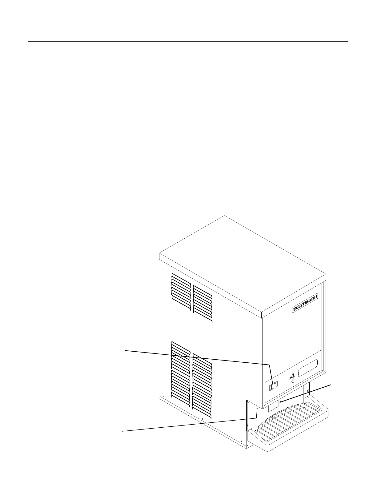
User Operation
Glass
Sensor
The TDE470 is an automa tic ice ven ding machine.
All it requires is coo l air, clea n water an d an
adequate supply of electrical power.
To Vend Ice:
Place a container in front of the Touch Free sensor
and below the ice spout. Hold it th ere until t he
container is full of ice. Do NOT overf ill t he
container or a bu ild up of ice in the sin k or a bac k
up of ice in the spout will occur.
To Vend Ice and Water.
Switch the W ater Switch to ON. Place a container
in front of the Touch Free sensor and b elo w the ice
spout. W ater an d ice will be dispense d into the
container be low th e spou t. Note : Th e water is NOT
cooled, it is the same te mpe rat ure as the build ing
supply water.
Daily Maintenance: Pour hot water into the sink to
flush out any debris or build up. Wipe the cabinet
off, wash the sink and grill to keep minerals from
accumulating.
TDE470
Caution:
Unless the touch free senso r is
de-activa ted by pushing the
Cleaning Swit ch in, ice and/ or wat er
may be dispense d during clean ing .
The Cleaning Switch is a button,
located to the left of the ice chute,
that temporarily shuts off the sensor
for c l eanup of the sp l a s h pane l .
Pushing the butto n in will disab le th e
sensor for 2 minute s, push ing the
button in again will return the sensor
to normal operation.
Water
Switch
Touc h Fre e
Disable
Switc h
February 1995
Page 9
Page 10

Bin Cover
TDE470
Component Location & Function
Evaporator. This is a vertical cylinde r full of wat er
and refrigerated. Also in the cylin der is a slowly
rotating auger. The auger force s th e ice up the
evaporato r walls and comp ress es it at the to p. The
resulting flake d ice then falls by gra vity into the ice
storage bin.
Water Reservoir. The water reservoir contains the
inlet float valve and the wate r level senso r. The
float valve controls the flow of water into the
reservoir, and the water level sensor will s top the
ice maker if the water su pply fails .
Ice Storage Bin. The ice sto rag e bin is an
insulated plastic contain er that is open at the top
and has a spout at the bottom. There is a rotating
ice va ne inside the b in that cause s the ice to be
swept over the spou t and disp en se d. The va ne is
rotated by a gear motor at the top of the bin.
Bin Cover. The bin co ver not only ke eps dirt from
the ice storage bin, it also is the support for the
dispense gear r educ er and the loc ation of the
electric eye bin controls.
Condenser. The TDE4 70 uses
an air cooled condenser. It blows
air out, away from the fan motor.
The heat removed fro m the wate r
is exhausted from the condenser.
Compressor. The re frig era tion
system compressor provides the
force to move the refrigerant
around th e sy stem .
Auger Drive. The auger drive is
a direct drive gear reduc er.
Compressor
Auger Drive
Water Reservoir
Evaporator
Ice Storage
Bin
Condenser
February 1995
Page 10
Page 11

Refrigeration System Operation
The TDE470 uses a f orce d d raf t condenser,
capillary tube and herme tic co mpre sso r. The
system uses R-134a as a refrige rant. High
pressure, high temp era tu re ref rigerant is forced
thru the conden ser whe re it loo se s eno ugh heat to
condense. The high pressure liquid ref rigerant
then passes thru the capilla ry tu be which ca use s a
pressure drop in the evaporator. As the high
pressure liqu id refrigeran t mov es int o the
evaporator’s area of low pressure, the warm water
and low pressure ca use the refrig erant to
evaporate and absorb heat from the metal walls of
the e vap o rator. After the re fr i g e rant ha s fl owed thru
the evaporato r it goes back to the co mpre sso r thru
the suction lin e as a low press ure vap or. At the
compresso r the cycle is repeated.
The TDE470 uses a low side pressu re co nt rol as a
safety, it will shut the system down if the suction
pressure is to o low for reliab le op era tio n.
TDE470
System Character i stics:
••Typical Low Side Pressure:
13 - 14 PSIG
••Typical Discharge Side Pressu re:
135 - 175 PSIG
••System Refrigerant Charge:
14 ounces of R-134a
Evaporator
Compressor
Capillary Tube
Dryer
Refrigeration System Schematic
Air Cooled
Condenser
February 1995
Page 11
Page 12

Sink Drain
TDE470
Water System Operation:
The water system consist s of a float valve,
reservoir and water dispense solenoid valve. The
water level in th e reservo ir t ank is the same lev el
as that inside the ev apora to r. Building water supply
flows to both th e flo at va lve and the sole no id. The
float valve will open to add water to the reservoir
as water flows out to the eva porator. The solen oid
will only open if the water switch is close d and the
touch free senso r initia te s an ice dispe ns e.
Evaporato r
Electric Eyes
Ice
Dispensi ng
Vane
Inside the evaporator there is a water seal. This
seal is the type that has a rotating half and a
station ary ha lf. The are a whe re t he two se als
touc h are smo oth flat surfa ces . Wh en the aug er i s
installed in the evapora to r, it forces the rotating
half of the sea l aga inst the stationary half. The
station ary half is spring-loaded and prov ides a firm
pressure ag ainst the auger portio n of the seal.
Water Level
Sensor
Float Valve
Water Seal
Inner Bin
Bottom
Water and Ice
Dispensing Spout
Water Dispensing
Soleno i d Valv e
Sink
Bin and
Reservoir
Overflow
Drain
Water Inlet
Connection
Water System Sch ematic
February 1995
Page 12
Page 13

Mechanical Operation
TDE470
General:
The TDE470 makes, sto res an d dispe ns es ice. It
also dispense s wate r. The ice making portion of
the machine pro du ces flake d ice at abou t 32
The ice falls thru a chute into the dispensing bin.
Above the cylindrical bin is a disp ense drive mot or
and electric eyes. The drive moto r is connecte d to
an ic e van e i n the bin . W he n the user ho lds a
container in front of the glass sensor and below
the ice chute, the dispense driv e motor rotates the
vane and the ice. The re is a slot in the ba se of th e
bin, located just above the vend spout and glass
filler lever. When the ice moves over that slot,
some of the ice on the bottom of the bin falls thru
the slot, into the chute and fills the container .
ON/OFF Control:
Flaked ice is produced by the ice maker until ice
builds up between the electric eye s. When the
electric eyes can no longer "see" each othe r, they
send a signal to the control board to shut the
machine off. The ref rige ration compressor stops
but the auger drive motor will continue to operate
for about 2 minutes to clear the evaporator of ice.
o
F.
Ice Vending
Dispensing takes place when the touch free
sensor’s infrare d be am boun ces back to the
sensor from a container pla ced direc tly in fro nt of
it, and under the ice chute.
When the beam is reflected back, it sign als the
circuit board to connect power to the dispense
drive motor, and ice is then move d over the slot in
the base of the bin, where it falls by gravity thru the
chut e in t o the con ta i ner.
If the Wat er swit ch is On , wat er is also dispens ed
at the same time.
Dispensing continues until the beam is no longer
refl ecte d ba c k to t he se nsor.
Water Control:
Because water is such an important requirement
for making ice, a water le vel sens or ha s been
placed in the rese rvoir. If the wat er su pp ly to th e
machine should fail, the water leve l sensor will
send a signal to the control board to shut down the
machine.
Refrigeration:
The refrigeration system uses a hermetic
compresso r (spec ifica lly design ed for R-134a ),
forced draft air cooled cond enser, capillary tube
and vertical flaked ice evaporat or. Inside the
evaporator is a slowly rotatin g auger. The auger is
supported by bearings at each end, and there is a
face-type wat er se al above the botto m bearing.
The auger is driven by a 1/10 HP direct drive gear
reducer. The auger drive mot or has a spee d
operated switch on it that will keep the compres sor
from operating if the auger motor is not tu rnin g at
full speed.
Water System
Water flows from the buildin g supply to the
reservoir and to the elect ric sole noid valv e. W at er
from the reservoir is used to make ice. W a te r the
flows thru the sole no id is disp ensed.
Touch Free Senso r
The bin, sink and res ervo ir ove rf lo w all have
drains.
February 1995
Page 13
Page 14

TDE470
Electrical Sequence
Refer the wiring diagram as needed.
The "Power" light on the board glows whenev er
there is power to the machine (and the master
switch is ON).
If the machine is switched off at the maste r switch ,
but is otherwise ready to go, switching the mast er
switch to ON does the following:
••The bin empty and power lights on the circuit
board glow.
•• There is a 15 second delay
••If there is enough water in th e reservo ir, th e
circuit board will allow the mach ine to start up.
Start up consists of:
••The compressor contactor coil receives power
from the circuit board.
••The contactor is energized, connec tin g power to
the compresso r, and the comp res sor st arts.
••The auger motor receive s powe r f rom the circu it
board and starts.
•• As ice goes past th e ice level sen so rs, th e bin
empty light will stay on and the machine will
continu e to run, unle ss th e ice st ays between
the sensors for more than 15 secon ds (bin full).
At that point , the bin empt y ligh t go es out, and
the machine shuts down.
Other reasons for shut down:
••Low water level (as sensed by the thermistor in
the reservoir).
••Excessive auger mo tor amp draw, measu red by
the circuit board.
••If the auger motor amp draw become s
excessive twice in an hour, the auger moto r is
shut down and the circuit board must be
manually reset. If th is condition occurs it mea ns
that the drive train is in need of cleaning.
maintenanc e or repair.
Shut Down consists of:
••The compressor contactor opens
••The compressor stops
•• The auger motor is run by the circuit board for 2
more minutes, clea ring out ice in the
evap o rator , and then
••The auger motor no longer receives power from
the circuit board, and the auger motor stops.
After a 6 minute delay, If the ice level senso r is
clear (bin empty ) f or more than 15 seco nd s, th e
machine will start up again.
Another purpose of the circuit board is to turn the
machine of f if there is not enoug h water in th e
machine.
••When the water level in the reservo ir f alls
below the tip of the water lev el sen so r, the
machine will "shut down"
••After a 6 minute delay, if the water refills the
reservoir, the mac hine will start up again.
Separate from the circuit board:
••If the high pressure control (cut out switch)
opens, the compressor will sto p immediately
(through the contactor ). It must be manually
reset.
••The master switch is the manual control for the
complete machine, but it is not a service
disconnect.
Ice Vending
••When a user places a con ta ine r in fron t of the
Touch Free ice senso r and belo w the ic e
delivery chute, the circuit board connects po wer
to the bin drive motor and ice is disp ense d for
as long as the container is present. If the user
does not remove the con tainer, ice will be
dispensed for 60 seconds and then stop.
••When a use r places a container in front of the
Touch Free water senso r, an d below the wat er
spout, the circuit board connect s power to the
water solenoid valve and water is dispensed. If
the user does not remo ve the cont ain er wat er
will be dispensed for 90 seconds and then stop.
Splash panel cleaning:
A switch , loc at ed to the left of the spout, may be
pushed to disable the Touch-Free sensor for
splash panel clea nin g. It automat ica lly rese ts af ter
2 minutes, or, if pushed wit hin the 2 minutes ,
resets the circuit board to enable the Touch Free
sensors.
February 1995
Page 14
Page 15

Maintenance:
Although the ice in this dis pe nser is comple tel y
untouched, the water and ice vending systems will
need to be periodically sa nit ized and
de-mineralized. The air cooled condenser will also
need to be kept clea n.
Schedule the sanitation, cleaning and
de-mineralization on a regular basis to keep the
ice clean and the machine operating efficiently.
Sanitation and Cleaning
Water System:
This ice machine requires periodic sanitation and
de-mineralization.
1. V end all ice fro m the mach ine .
TDE470
12. Repeat step s 3-11, except substitu te a locally
approved san itizing solu tion for the cleaner. A
possible sanitizing solu tio n may be obtained by
mixing 1 ounce of household bleach with 2 gallons
of clean, warm (95
o
F.-115oF.) water.
2. Remove top and right side panels .
3. Unplug or disconne ct electrical power.
4. Shut off water supply.
5. Drain reservoir.
6. Mix 8 ounces of Scotsman Ice Machine Cleaner
and 3 qu a rts of hot (95
Scotsman Ice Machine
Cleaner contains acids.
These compounds may
cause burns.
If swallowed, DO NOT
induce vomiting. Give
large amounts of wat er or
milk. Call Physician
immediately. In case of
external contact, flush
with water.
KEEP OUT OF THE
REACH OF CHILDREN.
7. Pour the water into the reservoir.
8. Wait 15 minutes fo r the cleaner to disso lve the
minerals inside the evaporator.
9. Plug in the machine or reconnect electrical
power.
10. A s the machin e opera tes, pou r i n the balan ce
of the cleaning solution.
11. Reconn ec t water supply, operate the machin e
for 15 more minutes, then switch it off.
o
F. -115oF.) potable wat er.
13. Unplug or disconnect electric al power.
14. Remove bin top, pour in warm pot able wat er to
melt out any ice.
15. Pull out the vane and bin bottom from the bin.
16. Thoroughly wash the bin’ s in te rior, bin top
interior, spout, ice vane and bin bott om with the
sanitizing solu tio n. Pour some down th e bin drain .
17. Reasse mble the bin bo tt om, van e and bin
cover .
18. Wash the sink are a with the sanit izin g solu tio n
and pour sanitizing solutio n down th e sink drain .
19. Replace all pane ls and reco nnect wate r and
electrical power.
Air Cooled Condenser:
1. Disconnect electrical power.
2. Remove top panel
3. Remove right and lef t side panels.
4. Use pressurized air to blo w the lint fro m t he
outside of the conde ns er in to ward s the fan moto r.
A vac uu m cleaner ho se place d on near the fan
motor should pick up most of the dust. Che ck fo r
interior dirt. If needed , use coil cle aner to
de-grease the condens er.
5. Replace all panels and reconne ct electrical
power .
February 1995
Page 15
Page 16

TDE470
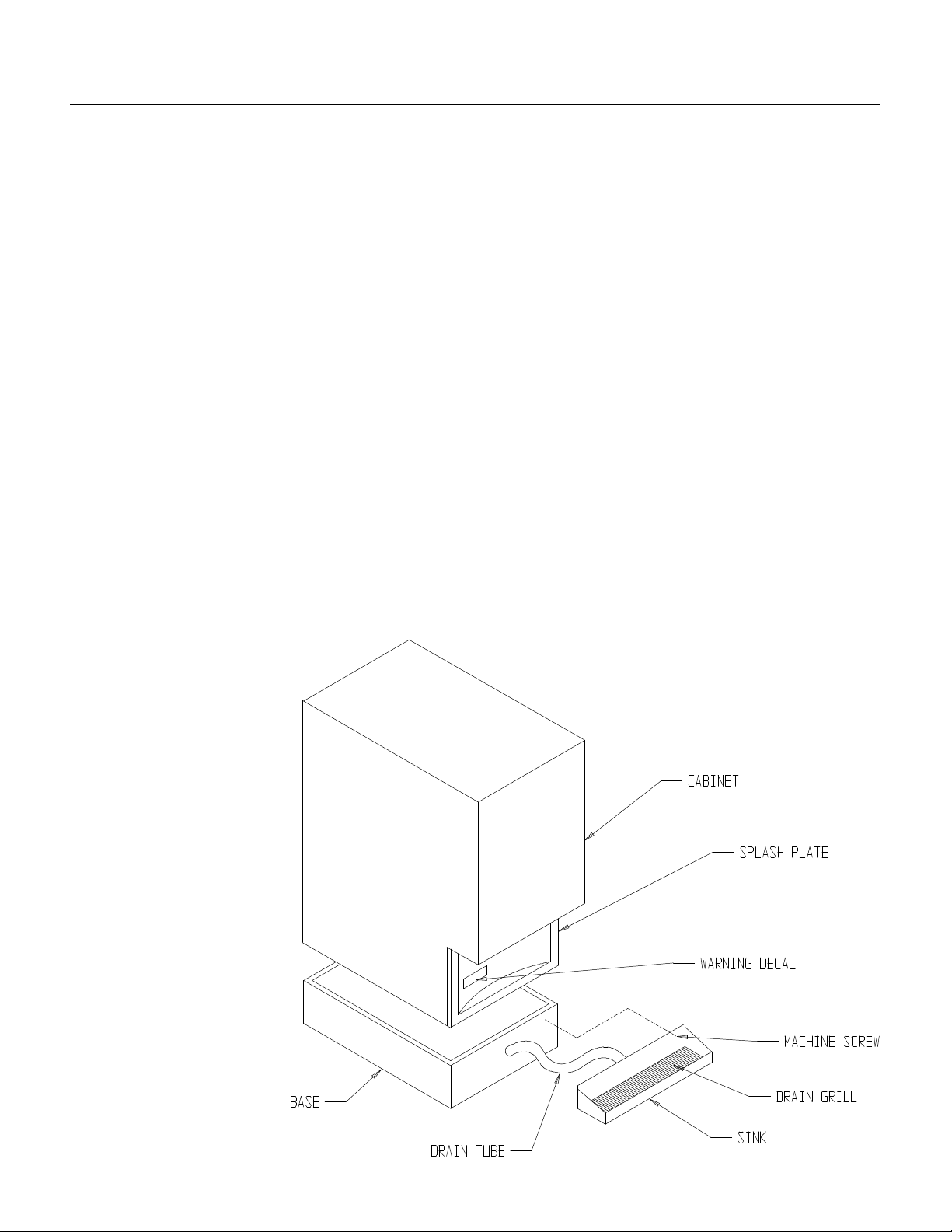
Dispense Area Sanitation
The dispense area is made up of the spout, sink,
grill and splash panel. It require s periodic cleanin g
and sa ni tatio n.
1. The spout may be removed by taking ou t the
two mounting screws. Wash and sanitize it.
2. The sink grill may be removed for was hin g and
sanitizing .
3. The sink should be flushe d with ho t wat er and
wiped clean with sanitizer.
4. The splash pan el req uire s sp ecial attent ion to
clean it.
••Push and release th e Clea nin g Swit ch located
to the left of the ice spout . This dis ables th e
Touch Free Se ns or so th e sp lash panel may be
cleaned without vendin g ice or wat er.
••Wash the splash panel and wipe with sanitizer.
••Re-push the clean switch or allow 2 minutes to
pass for the Tou ch Free system to reset .
February 1995
Page 16
Push Touch Free Sensor
Disable Butto n Befor e
Wiping Splash Panel
Pour Hot Water Into Sink
Regularly To Keep Drain
Line Open
Page 17

Auger and Bearing Inspection
Breaker
Water
Seal
While in most are as regular in-place clea nin g with
Scotsman Ice Machin e Cleaner will be adequate to
keep the interior of the evaporator free of
excessive minera l build up, some wat er co nd itio ns
may require more intense methods. In addition,
the auger bearings req uire physical inspe ctio n to
determine that they are not wearing . This physical
inspection is reco mmen ded twic e per year for the
top bearing and once per year for th e auger and
both bearings.
TDE470
Snap Ring
Auger & Bearings
Cap
Cap Screw
Whenever the auger is remove d, repla ce men t of
the water seal is reco mmen ded.
If a bearing requires replacement, the other
bearing must also be replac ed.
1. Unplug or disconne ct electrical power.
Rotating parts hazard.
Disconnect Electrical
Power Before Begin ning.
2. Shu t off th e w ater sup pl y.
3. Remove top panel.
4. Remove right side panel.
5. Drain the evapora to r and reserv oir.
6. Rem ove foa m cap on top of eva po r ator.
7. Remove 2 permagum plugs from the side of the
evapora tor .
8. Remove 2 screws (screwh eads were cov ered
by the permagum).
9. Pull up on the pull ring to remove the auger . If it
is difficult to pull:
Breaker
Screws
Bottom
Bearing
Washer
Top Bearing
Set
Auger
A. Remove the breaker co ver by takin g the snap
ring out.
B. Unscrew the auger bolt.
C. Use threaded rod or a slide hammer puller and
screw into the auger, slide the weight quic kly up
against the stop to remove the auger.
If the auger still will not move, bearin g replac ement
is mandatory. See Bearing Removal and
Replaceme nt .
Coupling
Adapter Stan d
February 1995
Page 17
Page 18

TDE470
Inspection: Auger
The auger is made of stainless ste el. It has a
polished surface that may be either sh inn y or dull,
but must be smooth. After removal, allow t he au ger
to dry to inspect for sca le. If mine ral scale is found
on the auger’s surf a ce , clea n of f th e auge r with ice
machine clea ne r and a scrub bing pad.
Remove the wate r seal an d cle an of f th e shou lde r
of th e auger.
Bearings: The top bearing should sp in f ree ly with
no rough spots. If it feels rough when spun by
hand, replace it. There should be minima l rust or
dirt. If in doubt, rep lac e the bearin g.
Note: The top bearing u sed in th e TDE 470 is a
"directional" bea ring . Not e which way th e inner
race is configure d and inst all int o t he brea ke r. The
breaker is also availa ble as a replacement part
with the top bearing already installed.
The bottom bearing must be removed from the
evaporator when replacing the water seal.
Remove bin cover.
Remove the thre e bolts holdin g the
evap or ator to the
gear motor adapte r
and lift the
evaporator up
slightly. Tap the water
seal and bo ttom
bearing out from the
top down. Check the
bottom bearing the
same way as the top.
Repl ace the w ater
seal and install a
new bearing set if
needed.
Outer
Race
To replace the water seal:
1. Remove old rota ting half from the auger. Clean
the mounting area.
2. Place a bead of food grade sealant (such as
Scotsman part number 19-0529-01) onto the
shou l der of the au ger wh er e the rotat ing ha lf of the
water seal will be installed.
3. Wash the new seal in water. While wet, slip it
onto the bottom of the auge r, rubber side toward
the auger. Push up until seated against the
sealant . Do not allo w any se alant to come into
contact with the face of the seal.
4. Wash the stationary half the water seal with
water. Slip it up into the botto m of the evapo rat or
until the bottom of the seal is inside the evaporator
abou t 1/4".
5. Push the bottom be arin g again st th e wat er se al
until the bottom bearing is insid e the evaporator
abou t 1/16" .
6. Rep lace the evap orato r o n th e adap te r, and
re-attach the stand using the original bolts.
7. Attach the auger to th e top bearing
and br eaker.
8. Return the auger to the evaporator
and slide it down until the splines touch
Inner Race
Wider on Top
Side
Open
Side s
the coupling.
9. Rotate the auger unt il the couplin g
splines alig n with the auge r.
10. Push the auger down, and rotate
the breaker u ntil the screw holes line
up with the pilot hole s in th e evapo rat or.
11. When the auger is comple tely
seated, reinst all th e break er scre ws.
12. Replace permagum and foam top.
Sealant
Here
Rubber
Smooth
Side
13. Switch on the water supply.
14. Check bin cover fo r elec trica l
grounds and switc h on the electrica l
power.
15. Observe ope rat ion . The unit should
make minimal noise while prod ucing
ice. Catch first 2 minutes of ice and
discard it.
16. Repla ce the bin cov er an d all
panels.
Water Seal
February 1995
Page 18
Page 19

Inspection:
Photo-Electric Eyes
The photo electric eyes used to "see" the ice build
up in the top of the bin cove r mu st be clean to get
a good "look" at the ice. If clou ded by mine ral
scale, the eyes will cause the ice machine to shut
off and sta y of f .
To clean the photo-electric ey es.
1. Remove the top panel.
2. Pull both of the photo-elec tric ey es out of thei r
rubber grommets.
3. Was h both eyes with a clea n cloth dipp ed in
Scotsman Ice Machine Cleaner.
4. W a s h the eye s off with clean wa ter.
5. Replace the eyes in the grommets
6. Replace the top pa nel
TDE470
Clean Photo-El ectric
Eyes
Water Level Sensor
The water level sens or may not sh ut the ice
machine off when the rese rvoir go es dry if there is
a film of mineral scale on the pro be tip.
1. Remove the top panel.
2. Remove the reservo ir cover .
3. Pull the water lev el pro be up and out of the
reservoi r.
4. Carefully wip e the tip of th e probe with a clean
cloth. Ice machine cleaner may be needed.
Note: The tip is made of glass.
5. Reinsert the water level sensor in the reservoir.
6. Replace the reserv oir cov er an d the top panel.
Coupling
Use the grease ze rk on the sid e of the coupling to
add greas e once pe r y ear.
Clean Water Level
Sensor
Wate r
Reservoir
That concludes no rmal main te nance . If the fan
motor has an oil plug, it may be oiled aft er 10
years of operat ion .
February 1995
Page 19
Page 20

TDE470
Service Diagnosis
PROBLEM POSSIBLE CAUSE PROBABLE CORRECTION
No ice is dispense d. No ice in bin due to:
••No electrical power
••Overuse
••Water sup pl y turned off
••Bin controls dirty
••Water sensor dirty
••Control system malfunction
••Auger drive motor open
•• Centrifugal switch op en
••Auger does not turn
•• No refrigeration
Ice in bin, but will not dispens e:
Drive motor does not turn
••Vend system does not work
••Dispense motor open
••Dispense output sha ft broken
Ice in bin, motor tu rns va ne .
Ice jammed up
••Users held cup against
dispens e spout and jammed
unit.
••Bin bottom slot not over spout
••Ice will not slide down bin wall,
bin out of round.
••Sink heigh t too small for
container us ed
••Wet ice in the bin from high
water level or hig h suctio n
pressure
Check/re sto re po wer
Recheck ice needs vs. mach ine
capacity.
Check water filter/hand valve/float
valve
Check & clean bin control (electric
eyes)
Check & clean water sensor
Check control system
Check auger drive motor
Check centrifugal switch
Check coupling & gear reducer
Check refrigeration system
Check/replace vend system
Check that clea ning switch has
been released.
Check/replace dispense motor
Check/replace output shaft
Advise owner/manager to instru ct
users.
Check bin bott om positio n
Check bin int erio r wall f or rou gh
texture or out of ro und.
Install sink ext ension ki t
Check water level, check suction
and discharge pressures
February 1995
Page 20
Page 21

TDE470
Service Diagnosis
PROBLEM POSSIBLE CAUSE PROBABLE CORRECTION
Unusual noiseMineral scale in evaporator Clean water system with ice
machine cle aner.
Auger coupling dry Grease co upling
Auger couplin g worn Replace co up ling and adapt er
stand.
Bearings worn Replace bearings and water seal.
Gear motor loose on frame Tighten bolts, check gromme ts
Low water level Check water level in reservoir
Tubing vibrating Check tubing for contact
Tooth on a gear missing Check gears in auger drive
Compressor to o loud Replace co mpre sso r
Gear noise Check gear motor for oil lea k
No water is dispensed Water Switch in Off po sit ion S witch to ON
Water switch open Replace switch
Water soleno id plu gg ed up Clean inlet scree n of solen oid
Water soleno id coil open Replace solenoid
Vend system does not work Check/re pla ce vend syste m
Water turne d off Re store water su ppl y
Water drips from spout Melting ice in chute Some water dripp ing is normal
Water soleno id leaks thru Replace solenoid
Ice jammed in spout Clear ice jam, check for cause
Ice will not stop dispens ing Vend syst em does no t work Check/re pla ce ve nd syste m
Water leaks from cabinet Evaporator water seal worn or
cracked
Tubing to evaporator leaks Replace tubing/fittings
Drain leaks Check drain tub es and fittings
External drain restricted Clean out drain
No refrigerat ion Ge ar mot or do es not turn Check moto r
Centrif ug al swit ch does not close Check switch
Fan motor does not t urn Check fan motor
Lack of refrigerant Add refrigerant, if problem is
Compressor does not pump Check/replace start capacitor
Replace se al an d bearin gs
redu ced , l oc ate leak a nd repair it .
Check/replace start relay
Check/re place compre sso r
February 1995
Page 21
Page 22

2 - Reset Button
TDE470
Service Diagnosis: Circuit Board
1
3
Circuit Board Lig ht
Identificati on
Explanation of Indicator Light or Reset Position On
Board
Will be On after the
machine must be clea ned and/ or ins pe cte d for drive train
maintenance and manually reset.
This button must be pushed if the auger moto r has overload ed
twice.
On at all times when the master switc h is ON and machine is
connected to electric al power.
On when ice level is low (unit mak ing ice). 4 Bin Empty,
Normal 6 minute off/de lay st art . To pre ven t short cycling, the
machine will not restart after any shut off (ex cpet power to the
board) until 6 minutes have passed.
Too much current has been drawn thru th e auger moto r. This
light is ON for the 30 minutes that must pass bef ore the mach ine
will automatically restart.
After the first Auger Motor Error, the next 60 minutes of operation
are monitore d, and this ligh t will be ON. If anothe r Aug er Mot or
Error occurs, the mac hin e shuts down.
On when water level is low in the reservo ir. 8 No Water ,
second auger motor trip, indicating that the
1 Auger Motor
2 Auger Motor Reset
3 Power,
5 Off Timer,
6 Auger Motor Error,
7 Auger Motor Timer,
4
5
6
7
8
Name and Meaning of
Light or Reset
Overload, ON =
Trouble
Button
ON = Normal
ON = Needs Ice
ON = Unit cycling off
ON = Trouble
ON = Trouble
ON = Trouble
February 1995
Page 22
Page 23

Electrical System
Bin and Water Level Sensors
There are two indica to r light s on the control bo ard .
The Bin Empty light glows when there is no ice
between the electric eyes.
The Wat er Le ve l light only glows when there is a
lack of water in th e reservoir.
If no lights, check for mis -alig nme nt of the electric
eyes or dirty eyes. Clean and or adjust as needed.
To check the electrical sys te m, first check th e lights
on the circuit board.
1. Remove the top panel.
2. Remove the right side pan el.
3. Remove the control box cover.
If the problem is that the machin e will not sta rt, and
the bin empty ligh t is glowin g and the water lev el
light is not, the gearmot or sho uld be che cke d. The
auger motor must start, and the switch on top the
motor close, or the comp ressor will not receive any
electrical power.
TDE470
February 1995
Page 23
Page 24

TDE470
Removal and Replacement
Panels:
1. Remove two screws at the bac k of the top panel.
2. Lift up at the back and push the top panel
forward to release it.
3. Remove 3 screws at the top, 3 screws at the
bottom and 1 screw at the front edge of each side
panel.
4. Push each side panel to the rea r to rele ase the
panel from the cabinet frame.
Dispensing System
The dispensing syst em consist s of the vend
switch, dispense motor, dispense vane, bin bottom
and bin.
Electrical Shoc k Haz ard
Disconnect electrical
power before beginning.
Dispense Va ne
1. Disconnect electrical power.
Dispense Drive
Motor
Bin Top
Dispense Gear Motor
1. Disconnect electrical power.
2. Remove top panel.
3. Remove one screw holding ground strap to
cabinet frame.
4. Cut off two dispe ns e mot or wire nuts.
5. Remove screws holding disp ense driv e gear
motor to the bin top.
6. Pull gear motor off the bin top.
7. Unscrew the output shaf t extension from the
gear motor.
8. Remove screws hold ing the mountin g bra cke t to
the gear motor.
9. Reverse to reas semb le, be certain that the new
wire nuts are secure and that th e groun d strap is
reattached.
2. Remove top panel.
3. Remove four thumb screws ho ldin g bin cover to
bin.
4. Lift bin cover off bin. Se t asid e.
5. Grasp the ice vane and pull it stra igh t up.
6. Reverse to reassemble.
Bin Bottom.
Perform steps 1-5 above (to remo ve th e dispe nse
vane) .
1. Lift bin bottom out of the dispense bin.
2. W h en repla cing, be sure tha t th e slot on the bin
bottom is over the dispense chute (at the front).
February 1995
Page 24
Page 25

Water System
Water Level
Sensor Slot
TDE470
The water system consist s of the reserv oir and
inlet water valve.
Reservoir.
1. Shu t off th e w ater sup pl y.
2. Remove the top panel.
3. Remove the right side pan el.
4. Drain the water res ervo ir and evaporator.
5. Disconnect inlet and outlet tubes from the
reservoir.
6. Remove screws holding reservoir to its
mounting bracket.
7. Remove reservo ir f rom th e machine.
8. Reverse to reassemble.
Float Valve
1. Shu t off th e w ater sup pl y.
2. Remove the top panel.
3. Remove the reservo ir cover .
4. Remove the water inle t tu be.
Va lve Plunger
1. After the valv e has been removed from the
reservoi r, remo ve the nut holdin g th e valve to its
mounting bracket.
2. Pull out the cotter pin to release the inte rna l
valve plunger.
Note: Do not replac e the pl ung er if the valve’s seat
is damaged. Rep lace the valve.
Inlet Water Valve.
1. Disconnect electrical power.
2. Shu t off th e w ater sup pl y.
3. Remove the top panel.
4. Remove the right side pan el.
5. Remove wire harness fro m inlet water va lve .
6. Remove tube connecting outlet of the valve to
the dispense tub e.
7. Rotate the valve to unscrew it from its inlet fitting.
8. Reverse to reassemble.
5. Push in the mounting tabs at the back of the
reservoir and lif t the valve ou t of the rese rvoir tank .
6. Replace with a new valve or replace the valve
plunger.
Plunger
Valve
February 1995
Page 25
Page 26

Snap Ring
Cap
Bolt
Washer
Water Seal
TDE470
Bearings, Water Seal and Auger
1. Disconnect electrical power.
Rotating parts hazard.
Disconnect Electrical
Power Before Begin ning.
2. Shu t off th e w ater sup pl y.
3. Remove the top panel.
4. Remove the side panels .
5. Drain the reservoir and evaporator.
6. Remove foam cap from the top of the
evapora tor .
7. Remove the two permagu m plugs from th e side
of th e evap orator.
8. Pull up on the ring to lift the auger out of the
evapora tor .
If the auger will not lift out:
1. Remove snap ring hold ing bearing cover t o
breaker.
2. Remove bearing cov er.
1. Remove three cap screws ho ldin g evaporat or to
the ad apte r s tand .
2. Lift evaporator up slightly an d tip the botto m out
to expose the splined end of the auger.
3. Remove snap ring hold ing bearing cover t o
breaker.
4. Remove bearing cov er.
5. Unscrew bolt holding bearing to auger.
6. Screw a length of threaded rod or a shoulder
screw into the auger.
7. Tap on the end of the thr eaded r od to push th e
auger out of the bottom of the evaporator.
8. Replace the bearings and water seal. Replace
the auger if the splines are dama ge d. Repla ce the
evaporator if more than 1/3 of the vertical rifle
grooves are gone. Sand or hone and sand the
inside of the evaporat or if mine ral build up is heavy.
3. Unscrew bolt holding bearing to auger.
4. Thread in a threa de d rod and weig ht or
slide-hammer puller into the auger.
5. Use the threade d rod & weight or slide hamme r
puller to remove the auger .
Or
1. Remove three cap screws ho ldin g evaporat or to
the ad apte r s tand .
2. Lift evaporator up slightly an d tip the botto m out
to expose the splined end of the auger.
3. Use a plastic mallet or dead-blow hammer to tap
the bottom of the auger and force the auger up. Do
NOT damage the splin es of the auge r or the auger
will have to be replaced.
If the auger is "frozen" to the botto m bearing , do
not force the bottom bearing thru the evaporator.
Top Bearing
Breaker
Auger
Coupling
February 1995
Page 26
Page 27

Bearing Replacement:
TDE470
Top Bearing Replacement
If the inner race is secure , us e an arbor press to
push the top bearing out of the breaker. If the inner
race has separa ted fro m t he bearing , rep lace the
breake r.
Insert a new bearing in the brea ker, check for
orientation :
The top of the bearing has a wider inne r race an d
a narrower outer race than the bottom.
Replace the "O" ring in the breaker.
Push the bearing in, push on ly on the out er race .
Water Seal & Bottom Bearing Replacement:
1. Remove old rota ting half from the auger. Clean
the mounting area.
2. Place a bead of food grade sealant (such as
Scotsman part number 19-0529-01) onto the
shou l der of the au ger wh er e the rotat ing ha lf of the
water seal will be installed.
3. Wash the new seal in water. While wet, slip it
onto the bottom of the auge r, rubber side toward
the auger. Push up until seated against the
sealant . Do not allo w any se alant to come into
contact with the face of the seal.
4. Wash the stationary half the water seal with
water. Slip it up into the botto m of the evapo rat or
until the bottom of the seal is inside the evaporator
abou t 1/4".
5. Push the bottom bearing against the
water seal until the bottom bearing is
inside the evapora tor abo ut 1/16".
6. Rep lace th e evap or a tor on the ad ap ter,
and re-attach the stand using the original
bolts.
Inner Race
Wider on Top
Side
7. Attach the auger to th e top be arin g and
breaker.
8. Return the auger to the eva porat o r an d
slide it down until the splines touch the
coupling.
Sealant
Here
Rubber
Smooth
Side
Outer
Race
Water Seal
Open
Sides
9. Rotate the auger until th e couplin g
splines align with the auger.
10. Pu sh the auger dow n, and r otat e the
breaker until the screw holes line up with
the pilot holes in the ev apora to r.
1 1. When the auger is comp let ely se at ed,
reinstall the breaker screws.
12. Replace perma gu m and foa m top.
13. Switch on the water supply.
14. Check bin cover for electrical groun ds
and switch on the electrical power.
15. Observe opera tio n. The unit should
make minimal noise while producing ice.
Catch firs t 2 minute s of ice and discard it.
16. Replace the bin co ver and all panels.
February 1995
Page 27
Page 28

TDE470
Refrigeration System
This ice machine uses R-134 a as the refrige ran t.
This refrigera nt has no chlorine , and th ere fore
requires polyolester type ref rige ran t o il. This oil
requires specific service pro cedures.
General Service
A HFC type liquid line drier is required. "Standard"
driers may not take out enough moist ure and may
affect th e oil addit ive s.
The time that the refrigera tio n sys tem is open to
the air must not exceed 15 minutes. The oil will
rapidly absorb moisture from the air, and the
contact time must be kept to a minimum.
A spe cia l o r very sensitive elect ron ic leak det ect or
will be needed to locate refrigerant leaks. Many
are on the market that will sense R-134a.
The access va lves must be in the close d posit ion
before the hose caps are removed . Do not remo ve
the hose caps before checking the position of the
valve. Use a 3/16" allen wrench to open and close
the valve.
Stem Cap
Torque Stem
to 6-8 ft. lb.
Access Valve
As with any other ref rige ran t, do not pla ce
pressurize d air or oxy gen int o the ref rige rat ion
system.
Note: The refr igera tion system uses an HFC
type refrigerant and MUST use an HFC type
drier .
Torque to 8-12 ft. lb.
Fitting Cap
Torque to 7-12 ft. lb.
Temperatu re Pre ssure Chart, Sele cte d Points
Temperatu re in
0
F. PSIG of R-134a
-102.0
-6 3.7
-4 4.6
-2 5.5
06.5
17.0
27.5
38.0
48.6
59.1
10 12.0
12 13.2
14 14.4
16 15.7
18 17.1
20 18.4
25 22.1
30 26.1
31 26.9
32 27.8
33 28.6
34 29.5
35 30.4
40 35.0
45 40.0
50 45.4
75 78.7
90 104.3
110 146.4
120 171.1
130 198.7
150 262.8
Evacuation to 200 microns is recommen ded.
February 1995
Page 28
Page 29

Gear Reducer Removal
TDE470
1. Disconnect electrical power.
Electrical Shoc k Haz ard
Disconnect electrical
power before beginning.
2. Shu t off th e w ater sup pl y.
3. Remove the top and side panels .
4. Remove the control box cover.
5. Remove the centrifugal switch co ver on the top
of the auger drive motor.
6. Disconnect the electrical wires from the
centrifugal switch.
7. Drain the evapora to r and reserv oir.
8. Disconnect the water inlet tube from the
evaporator.
9. Remove the three screws holdin g th e
evaporator to the adapter stand.
10. Lift the evaporato r u p hi gh enough fo r the
auger to clear the adapter stand.
11. Remove th e mou nt ing bolt s ho ldin g the ge ar
reducer to the cabin et frame .
12. Trace auger driv e motor wires b ack to the
control box.
13. Disconnect the drive motor wires from the relay
on the circuit board.
14. Pull the wires back to the auger drive moto r.
15. Pull the gear reducer out the side of the
cabinet to remo ve it fro m t he mach ine.
Note: If there is evidence of water near the output
shaft of the gear reducer, it would be a wise
precaution to pull the auger from the evaporator
and check the bearing s.
16. Rebuild or replace the gear reducer.
Motor Cover &
Bearing
Fan
Stator
Rotor
Rotor
Bearing
Shaft Seals- 2,
back to back
E-Clip
Woodru ff Ke y
Output Gear
Gear Reducer Components
Gear Case
February 1995
Page 29
Page 30

TDE470
Auger Drive Motor
The windings or top bearing & cover may be
replaced without removing the evaporator or gear
reducer fro m the ma chin e.
1. Disconnect electrical power.
Electrical Shoc k Haz ard
Disconnect electrical
power before beginning.
2. Shut off water supply.
3. Remove top panel.
4. Remove right side panel.
5. Drain the reservoir and evaporator.
6. Disconnect the reserv oir ou tle t tube from th e
bottom of the reservoir.
7. Remove screws holding reservoir mounting
bracket to the cabinet.
8. Lift the reservoir up & away from the top of the
auger drive motor.
9. Remove the 4 bolts holding the auger motor
cover to the gear reducer case.
10. Lift the plastic switch housin g off the auger
drive motor.
If the rotor needs to be removed:
1. Run a screw into the top of the rotor.
2. Grasp the screw with a grip pliers.
3. Pull and/or tap on the pliers to pull the rotor &
bearing out of the gear reducer.
4. Inspect the bearin g and inp ut seal. Rep lace
them if worn.
Note: When the rotor is re-inst alled, be certain that
the bearing is fully seate d in the gear cas e.
Gear Reducer Rebuild
1. After the gear reducer has b ee n removed, the
internal components may be inspected and/or
replaced . Remo ve all bolts hold ing the two cas e
halves together.
2. Tap against the roll pins at each end of the gear
cases to split them.
3. Pry the case halves apart.
4. Check the internal condition of the gear reducer.
If rusty or wate r is prese nt , rep lac e the comp let e
assembl y. The oil should be black and the prop er
oil level is 1/8" from the top of the biggest gear
(with all gears installed). Check the input seal.
The gears may be replaced individually.
1 1 . Hold the cent rif u gal s witch and remov e the
screw holding it to the rot or of the motor.
12. Lift the centrifugal switch up and off the motor.
13. Lift the motor co ver up and off the motor.
14. Pull the fan up and off the rotor.
If the windin gs are to be rep lace d, remov e th e lef t
side panel and control box cov er.
1. Locate the auger drive motor wires plugge d into
a relay on the circuit board.
2. Disconnect the auger motor’s wires and pull
them back to the auger drive motor.
3. Lift the auger mot or wind ing s of f the gear
reducer.
February 1995
Page 30
 Loading...