

Page 1

CMS1202
INTRODUCTION
To the owner or user: This service manual is
intended to provide you and the maintenance or
service technician with the information needed to
install, start up, clean, maintain and service this
ice system.
Table of Contents
Specifications . . . . . . . . . . . . . . . . . . . . . . . . . . . . . . . . . . . 2
Location & Assembly . . . . . . . . . . . . . . . . . . . . . . . . . . . . . . . . 3
Stacking . . . . . . . . . . . . . . . . . . . . . . . . . . . . . . . . . . . . . 4
For the Electrician . . . . . . . . . . . . . . . . . . . . . . . . . . . . . . . . . 5
For the Plumber . . . . . . . . . . . . . . . . . . . . . . . . . . . . . . . . . . 6
Final Check List . . . . . . . . . . . . . . . . . . . . . . . . . . . . . . . . . . 7
Initial Start Up . . . . . . . . . . . . . . . . . . . . . . . . . . . . . . . . . . . 8
Freeze Cycle Operation . . . . . . . . . . . . . . . . . . . . . . . . . . . . . . . 10
Harvest Cycle Operation . . . . . . . . . . . . . . . . . . . . . . . . . . . . . . . 11
Component Description . . . . . . . . . . . . . . . . . . . . . . . . . . . . . . . 12
Cleaning . . . . . . . . . . . . . . . . . . . . . . . . . . . . . . . . . . . . . 15
Adjustments . . . . . . . . . . . . . . . . . . . . . . . . . . . . . . . . . . . . 17
System Specifications . . . . . . . . . . . . . . . . . . . . . . . . . . . . . . . . 19
Service Diagnosis . . . . . . . . . . . . . . . . . . . . . . . . . . . . . . . . . 20
Removal and Replacement . . . . . . . . . . . . . . . . . . . . . . . . . . . . . . 23
Parts Lists and Wiring Diagrams are located
in the center of this manual, printed on
yellow paper.
September 1993
Page 1
Page 2
Air Cooled
CMS1202
FOR THE INSTALLER
The CMS1202 will fit Scotsman’s ice storage bin
(48" wide) model BH900, and with adaptors, the
following Scotsman ice storage bins:
••BH1000 (use KBT21)
••BH1360.
When stacking onto another CMS1202 or a
CMS1402, use kit KSCMS48.
The normal finish for the machine is enamel
sandalwood. An optional stainless steel panel kit
(SPKCMS1402) can be field installed. It contains a
stainless steel top, left side panel, an overlay right
side panel, and front panel.
Water Cooled
Scotsman Ice Systems are designed and
manufactured with the highest regard for safety
and performance. They meet or exceed the
standards of U.L., N.S.F., and C.S.A.
Scotsman assumes no liability or responsibility of
any kind for products manufactured by Scotsman
that have been altered in any way, including the
use of any parts and/or other components not
specifically approved by Scotsman.
Scotsman reserves the right to make design
changes and/or improvements at any time.
Specifications and designs are subject to change
without notice.
This manual covers A and B models.
Model Number Dimensions (w/o bin)
W" x D" x H"
CMS1202AE-3B
CMS1202WE-3B
CMS1202AE-32B
CMS1202WE-32B
48 x 24
48 x 24
48 x 24
48 x 24
3
⁄8 x 271⁄
3
⁄8 x 271⁄
3
⁄8 x 271⁄2
3
⁄8 x 271⁄2
Basic
Electrical
208-230/60/3 14.8 20 60 oz. R-22 Air
2
208-230/60/3 14.1 20 64 oz. R-22 Water
2
208-230/60/1 20.8 30 60 oz. R-22 Air
208-230/60/1 20.1 30 64 oz. R-22 Water
Minimum Circuit
Ampacity*
Maximum
Fuse Size
Refrigerant
Charge
Condenser
Type
* Minimum Circuit Ampacity is used to determine wire size and type per the National Electric Code. If the
nameplate has different numbers from the above, go by the nameplate.
This ice system is designed to be installed indoors, in a controlled environment.
MINIMUM MAXIMUM
Air Temperature 50
Water Temperature 40
Water Pressure 20 psi 80 psi
0
F. 1000F.
0
F. 1000F.
September 1993
Page 2
Page 3
FOR THE INSTALLER: Location & Assembly
SHIPPING
BRACKETS
Location:
After uncrating and inspection, the unit is ready for
installation. It is important that the machine be
installed in a location where it has enough space
around it to be accessible for service. A minimum
of 6" must be allowed at the back for air circulation
on air cooled models. Try to avoid hot, dirty and
crowded locations. Be sure that the location for the
machine is within the envrionmental limitations.
Storage Bin:
Tip the storage bin on its back, using parts of the
carton to protect the exterior finish. Install the legs,
use a heavy duty leg kit if stacking two ice
machines on one bin.
1. Arrange for proper electric, water and drain.
See instructions for the plumber and for the
electrician.
2. After mounting the legs, position the ice storage
bin in the selected location:
CMS1202
ICE MACHINE AND BIN ASSEMBLY
Note: Allow enough space to the left and back to
service the machine. Do NOT push the bin into
postion, instead, lift it there. Pushing a bin may
damage the legs and leg mounts.
Level the bin in both the front to rear and side to
side directions by adjusting the leg levelers.
Select a well ventilated location for air cooled
models.
Note: Air cooled models blow air from front to back.
3. Inspect the bin top mounting gasket which
should be flat, with no wrinkles, to provide a good
water seal when the cuber is installed on top of the
bin.
Ice Maker:
Install the modular cuber on top of the bin using
care to be sure a good seal is made between the
two cabinets. Use of a mechancial lift is
recommended. Align the holes in the bottom rear
of the cabinet to mate with the two mounting holes
on the top rear of the bin.
Use bolts and straps found on the back of the
icemaker to secure the ice machine to the bin.
When alignment and leveling are completed,
tighten the bolts to secure the mounting straps.
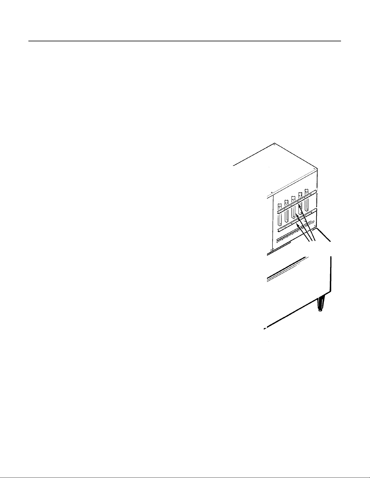
Remove the front panel, and remove the
evaporator shipping brackets and hardware.
September 1993
Page 3
Page 4
CMS1202
FOR THE INSTALLER: Location & Assembly
Stacking Instructions
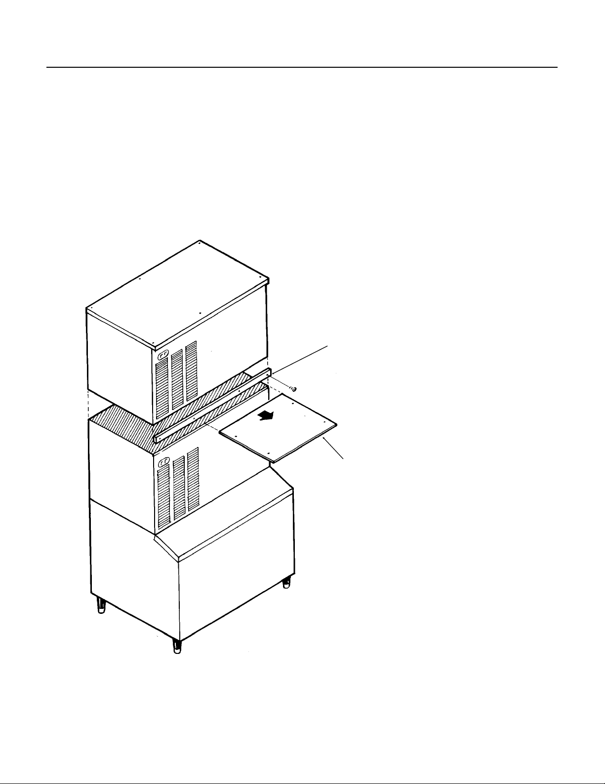
When stacking two units, remove the top panel
and the evaporator cover from the lower icemaker.
(The top removed from the lower icemaker will no
longer have any function.)
Carefully lift the uncrated top unit onto the bottom
one and align the two cabinets. Use of a
mechanical lift is recommended for this step.
STACKING
At the back of the two icemakers, bolt the upper
icemaker cabinet to the lower icemaker cabinet
using the mounting straps and bolts from the
hardware package.
A stacking kit is required to interconnect the CMS
ice level controls.
A different stacking kit is required to stack a CMS
machine onto a CM model.
OPTIONAL TRIM STRIP
September 1993
Page 4
EVAPORATOR COVER
Page 5
FOR THE ELECTRICIAN
ELECTRICAL CONNECTIONS, AIR COOLED
DETAIL OF
JUNCTION BOX
CMS1202
SEE NAMEPLATE for current requirements to
determine wire size to be used for electrical
hookup. The cuber requires a solid chassis to
chassis earth ground wire. See Wiring Diagram.
Be certain the cuber is connected to its own
electrical circuit and individually fused. Voltage
variation should not exceed ten percent of the
nameplate rating, even under starting conditions.
Low voltages can cause erratic operation and
may be responsible for serious damage to the
icemaker.
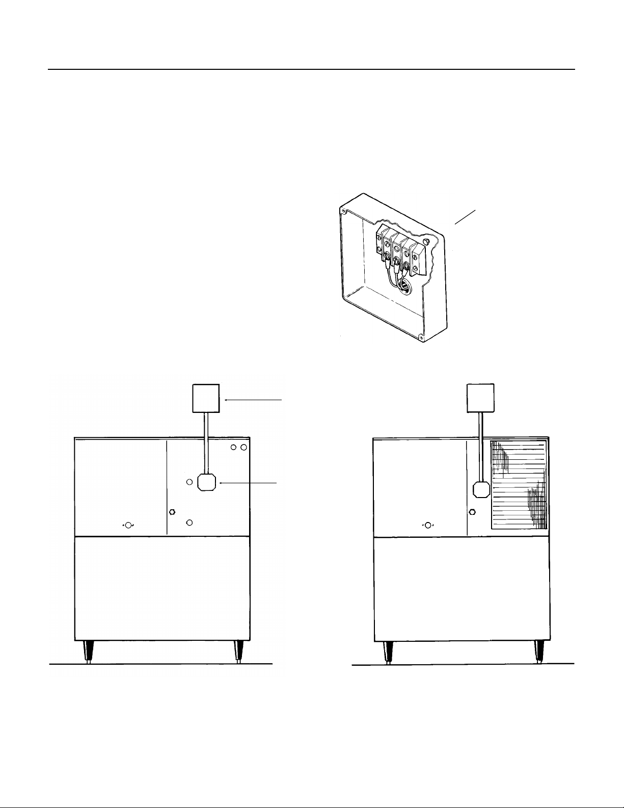
Electrical connections are made at the rear of
the icemaker, inside the junction box.
All external wiring should conform to the
national, state and local electrical code
requirements. Usually an electrical permit and
services of a licensed electrician will be
required.
GROUND SCREW
HAND
DISCONNECT
SWITCH
JUNCTION
BOX
ELECTRICAL CONNECTIONS, WATER COOLED
September 1993
Page 5
Page 6
VENT
OPTIONAL
FILTER
CONDENSER
INLET
CMS1202
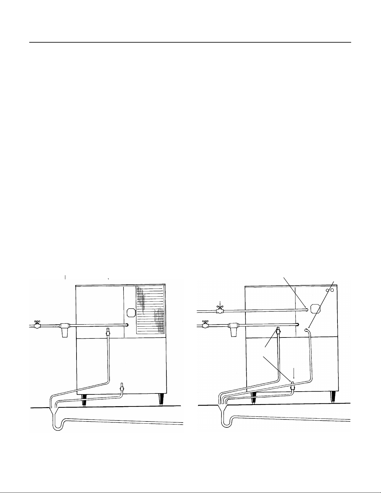
FOR THE PLUMBER
FOLLOW ALL LOCAL CODES:
The recommended water supply line is a 3/8-inch
O.D. copper tubing with a minimum operating
pressure of 20 PSIG and a maximum of 80 PSIG.
Connect to cold water supply line with standard
plumbing fittings, with shut off valve installed in an
accessible place between thewater supply and the
cuber. ln some cases a plumber will be required.
Water Limitations:
An ice machine is a food manufacturing plant, it
takes in a raw material, water, and turns it inot a
food product, ice. The purity of the water is very
important in obtaining pure ice and in maximizing
product life. It is generally better to filter the water,
although there is no one filter that will cure all
water problems. A good filter combined with a
polyphosphate feeder gives about the best overall
performance.
DRAIN
Connections: All drains are gravity type and must
have a minimum of 1/4-inch fall per foot on
horizontal runs. The drains to be installed to
conform with the local plumbing code. Install a
vertical open vent on drain line high point to insure
good draining. The ideal drain receptacle is a
trapped and vented floor drain. Recommended bin
drain is 5/8 inch O.D. copper tubing and should be
vented and run separately. Insulation for high
humidity areas is recommended.
Terminate drains above the drain receptacle with
the proper air gap per local code.
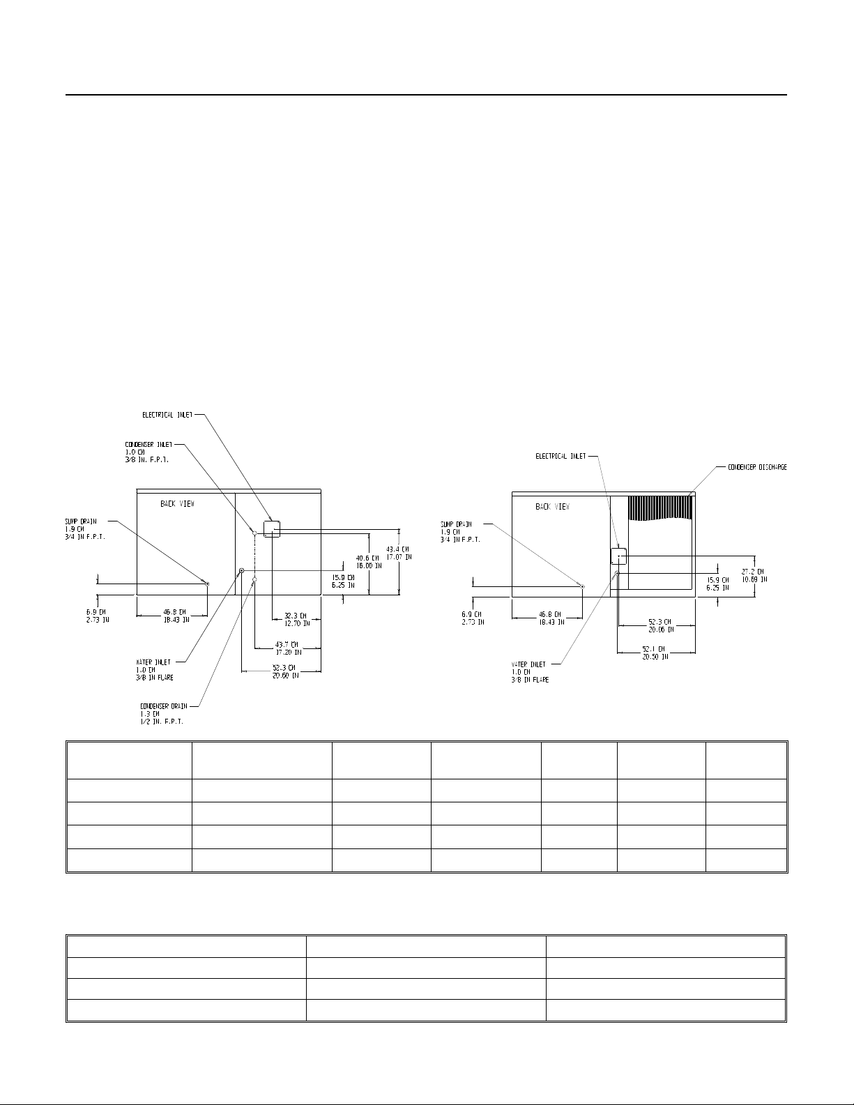
The ice machine sump drain is 3/4" FPT. There
must be a vent at this connection for proper sump
drainage.
WATER COOLED MODELS: On water cooled
models, a separate cold water supply inlet is
required, to be connected to a 3/8-inch female
pipe thread (FPT) fitting at the rear of the cabinet.
An additional drain line is required to drain the
water cooled condenser, and must not
interconnect to any other of the unit’s drains.
POTABLE
WATER
SUPPLY
AIR GAP
BETWEEN
DRAIN LINES
AND
BUILDING
DRAIN
3/8" MALE
FLARE
3/4" FPT
AIR COOLED
CONNECTIONS
SUMP DRAIN MUST
BE VENTED
HAND SHUT OFF
VALVE
AIR GAP
BETWEEN DRAIN
LINES AND
BUILDING DRAIN
WATER COOLED
CONNECTIONS
CONDENSER
DRAIN
BIN
DRAIN
WATER SUPPLY AND DRAIN CONNECTION
September 1993
Page 6
Page 7
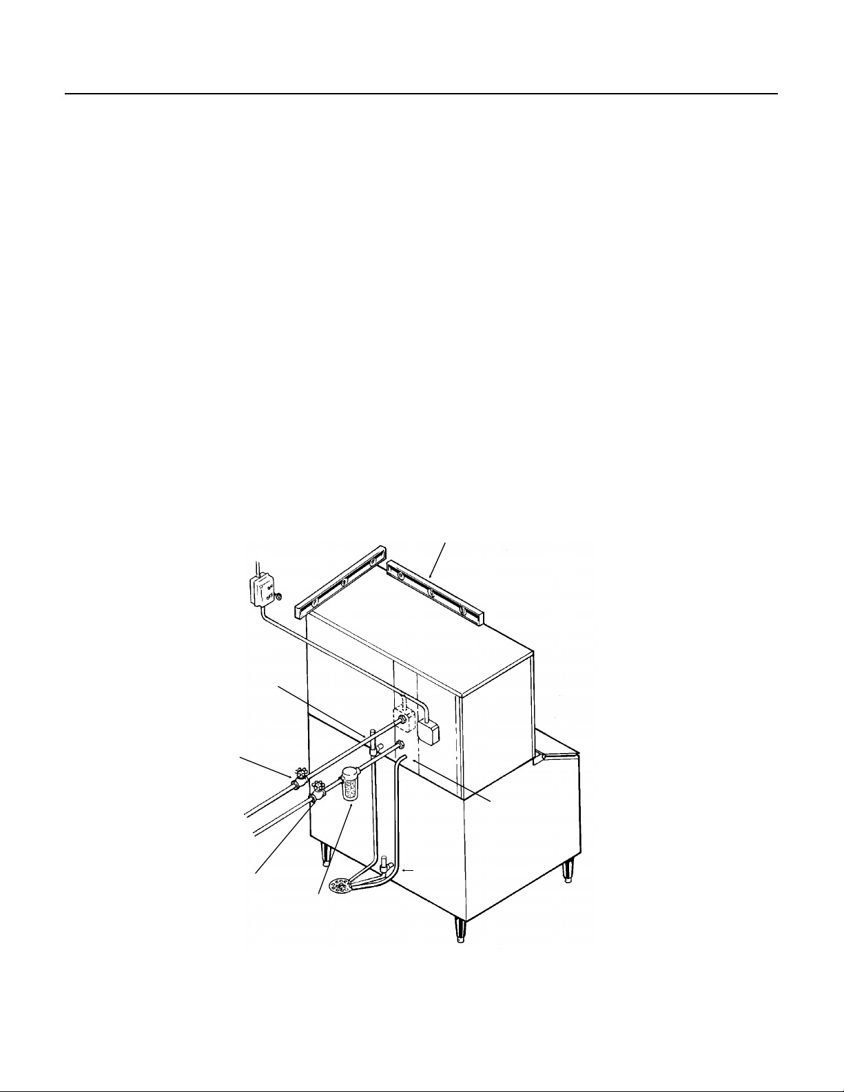
FINAL CHECK LIST
CMS1202
1. Is the cabinet in a room where ambient
temperatures are within the minimum and
maximum temperatures specified?
2. Is there at least six inches clearance at the left
and back sides of the cabinet for proper air
circulation? (Air Cooled models)
3. Has water supply pressure been checked to
insure a minimum of 20 PSIG and a maximum of
80 PSIG operating pressure?
4. Is the cabinet level?
5. Check that any shipping material has been
removed from inside the cabinet.
6. Check that the reservoir is properly secured to
the bottom of the evaporator plates.
7. Have all electrical, water and drain connections
been made?
8. Is the water supply line shut off valve installed
and electrical wiring properly connected?
9. Check all refrigerant lines and conduit lines, to
guard against vibration or rubbing and possible
failure.
10. Have the bin and cabinet been wiped clean?
11. Has the Manufacturers Registration form been
properly filled out? Check for correct model and
serial numbers from Serial nameplate, then mail
the completed card to the SCOTSMAN factory.
12. Has the owner/user been given the Service
Manual and instructed how to operate and
maintain the icemaker?
13. Has the owner been given the name and
telephone number of the authorized SCOTSMAN
Service Agency serving him?
DRAIN
HAND SHUT OFF
VALVE
HAND SHUT
OFF VALVE
LEVEL ASSEMBLY
SUMP
WATER
COOLED
DRAIN
BIN
DRAIN
OPTIONAL
FILTER
FINAL INSTALLATION
September 1993
Page 7
Page 8
HARVEST
PORTION
FREEZE
PORTION
CMS1202
INITIAL START UP
1. Remove the front panels by removing screws at
the base and pulling out.
2. Remove two screws and the control box cover.
3. Check that the two switches on the control box,
the ICE-OFF-WASH rocker switch and the
COMPRESSOR ON-OFF toggle switch are in the
OFF position.
4. OPEN the water supply line shut off valve.
5. Switch the electrical power ON.
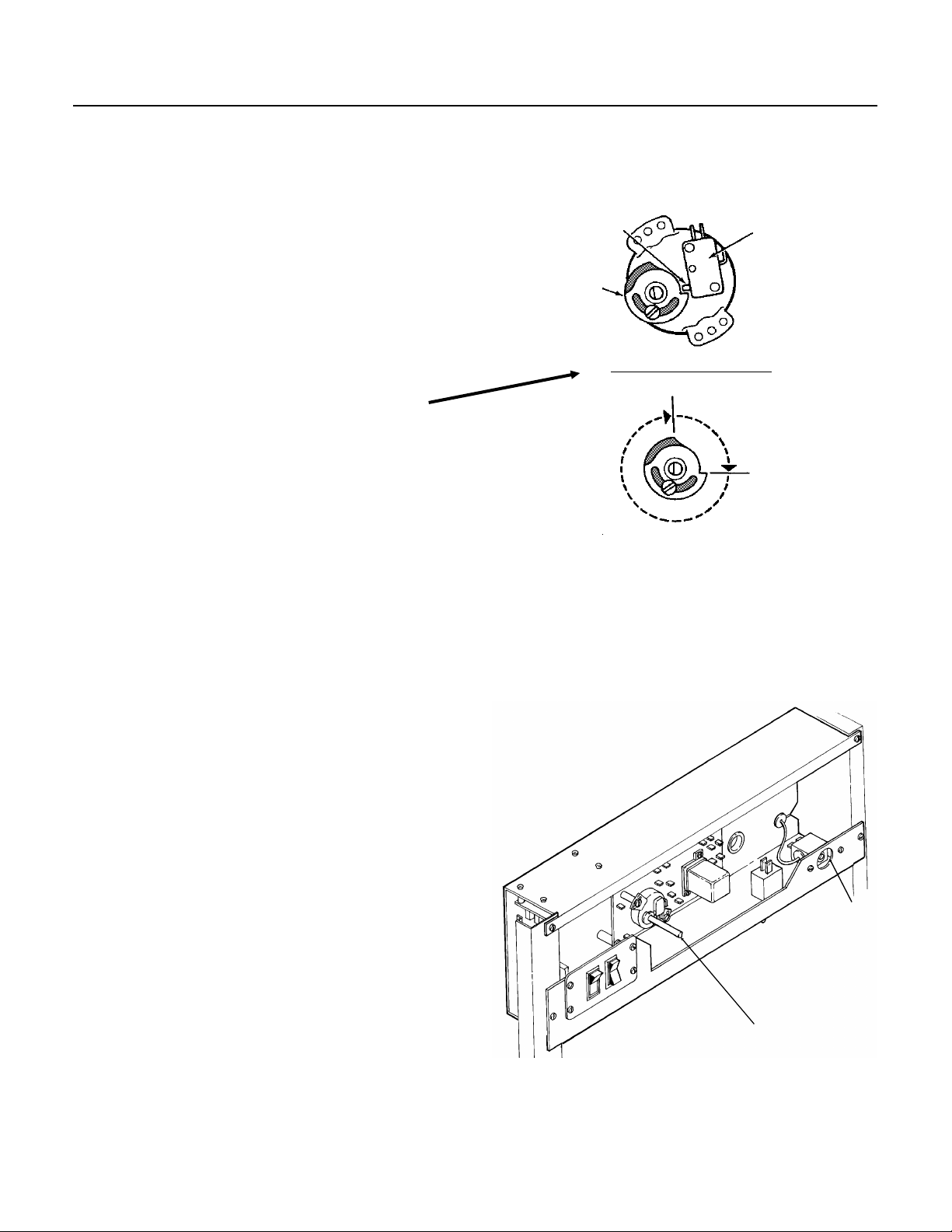
6. Inside the control box is the shaft of the timer
and the switch assembly. Rotate the shaft of the
timer and switch assembly clockwise until the cam
is lined up as shown in “Front View of Timer”.
7. Move the ICE-OFF-WASH rocker switch to the
ICE position.
8. Check the water fill cycle: For several minutes
the inlet water valve will be open and water will
flow into the reservoir. Near the end of the fill
cycle, water should be overflowing the reservoir
and draining thru the reservoir drain. If at the end
of the fill cycle the reservoir is not full, repeat step
6.
FRONT VIEW OF TIMER
ACTUATOR
BUTTON
CAM
MICROSWITCH
Check that the sump covers are snapped in place.
Check that the water distributors are properly
seated at the top of the evaporators, and that
water is flowing over all cube cells.
Note: Some water spray from the evaporators is
normal when the machine is new. The spray will
quit after a few cycles.
9. When the sump has filled, move the compressor
ON-OFF toggle switch, to the ON position.
10. On air cooled models the fan motors will begin
to blow warm air out the back of the machine.
Water cooled models will begin to flow warm water
out of the condenser drain.
Note: To optimize the balance between ice
production and water use, the freeze cycle
discharge pressure must be 220 P.S.I.G. Check
discharge pressure and adjust the water regulating
valve to obtain 220 P.S.I.G. discharge pressure.
11. Check operation of the freezing cycle: Ice will
begin to form from the top of the evaporators
down. After the first cycle freezing time will range
between 15 and 18 minutes. Freeze cycle time is
longer for temperatures above 70
when temperatures are below 70
o
F. and shorter
o
F. Average
complete cycle time is about 19 minutes.
CONTROL BOX
CUBE SIZE
CONTROL
TIMER
September 1993
Page 8
Page 9
INITIAL START UP
12. After an ice harvest check Cube Size. There
is just enough water in the reservoir to make one
full sized batch of cubes. The water pump may
pick up some air at the end of the freezing cycle
and then bubbles in the pump discharge hose are
normal. If the water pump quits pumping water, the
cube size control may be set too cold, or the water
system may be leaking water.
CMS1202
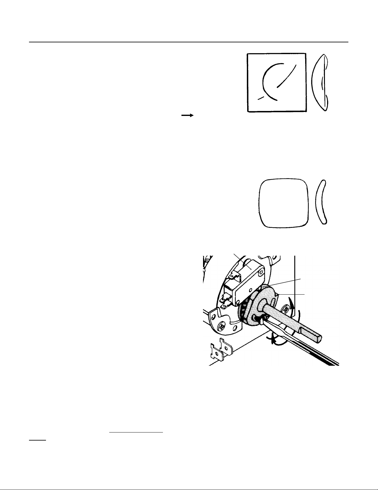
CUBE SIZE DIAGRAM
JUST RIGHT
Compare cube size to the "Cube Size Diagram".
To adjust cube size, locate the cube size control in
the front of the control box, and rotate the
adjustment screw one eighth of a turn
COUNTER Clockwise to produce SMALLER sized
ice cubes
Clockwise to produce LARGER ice cubes
Check the size of ice cubes in the next cube
harvest and repeat the adjustment until the correct
ice cube size is achieved.
13. Check Harvest Time. There must be enough
time in harvest to defrost all the cubes, but not an
excessive amount that will waste capacity. The
length of the harvest cycle is determined by the
timer cam positions.
If needed, adjust the harvest time so that there are
about 15 seconds of harvest time left after the last
cube has fallen off the evaporators.
Because harvest time varies with the water and air
temperatures at the ice machine, colder air and
water will result in faster ice making, but longer
harvest cycles. Do not adjust harvest time too
short or the unit will not harvest all the ice.
When the cubes are the correct size, they will be
connected together vertically, and drop off in strips.
The batch weight will be about 13.5 to 14.5 lb.
Note: If the cubes at the bottom rows of some evaporators
are smaller than others. the size difference does not affect
capacity or performance. However, there should be some
ice in all cells. If not, contact the Factory.
TOO SMALL
MICROSWITCH
CLOSE UP
VIEW OF TIMER
SWITCH
ACTUATOR
CAM
The harvest time is set by: loosening the set screw
on the cam, rotating the shaft so that the opening
between the cams increases or decreases,
retightening the set screw when the cams are in
the desired position. More of an opening between
the cams = more harvest time.
An adjustment of the cube size control may be
needed after the harvest time has be changed.
Check cube size again.
14. Check Bin Ice Level Control: With the
icemaker in a harvest cycle, place something flat &
solid directly below the sensor socket (located
near the center back of the base). The machine
will then switch OFF at the
end of the harvest
cycle. Within seconds after removal of the
obstruction the icemaker will restart.
September 1993
The control has two postions, FULL and PARTIAL.
Full shuts the machine off when ice is 8" from the
bottom of the sensor socket. The control will not
work on bins taller than 8’.
15. Replace all covers, panels and screws.
16. Fill out and mail in the Warranty Registration
and Customer Response form. Explain to the
owner/user the operation and maintenance
requirements of the ice machine. Inform the owner
of the name and telephone number of the local
SCOTSMAN Distributor or service agency.
Page 9
Page 10
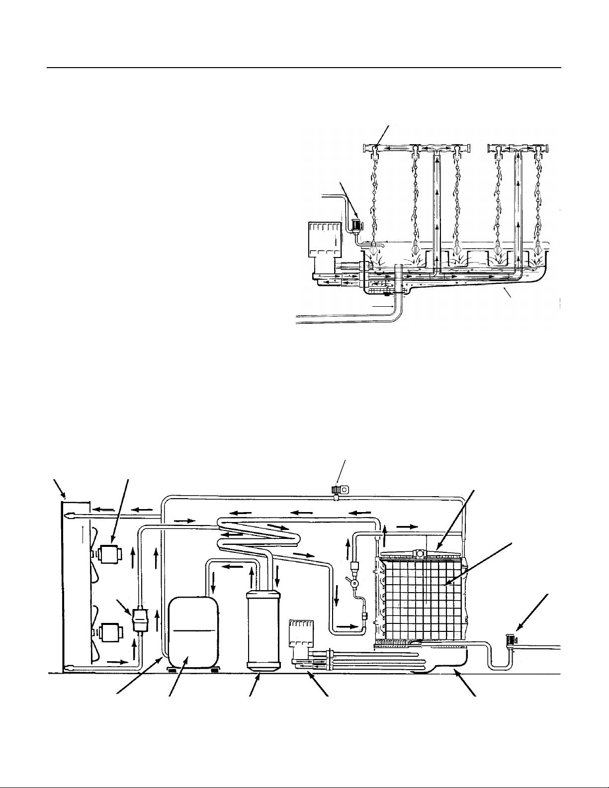
EVAPORATOR
CMS1202
FREEZING CYCLE OPERATION
Water from the sump assembly is pumped to the
water distributor system at the top of each
evaporator plate. From the water distributor the
water cascades by gravity over all cells of the plate
and to the sump assembly below.
WATER DISTRIBUTION
At the beginning of the freezing cycle, the electrical
circuit is completed to the compressor and the
water pump. The water pump operates
continuously, through both the freezing cycle and
the harvest cycle.
In water cooled models, water also flows through
the condenser and out the drain.
During the freezing cycle, the hot gas solenoid
valve and the water inlet solenoid valve are
CLOSED. When the ice cubes are partially
formed, the cube size control (sensing bulb
attached to the suction line) will CLOSE, and
connect power to the timer motor. The timer then
controls the remainder of the freezing cycle. The
timer will keep the icemaker operating in the
freezing cycle for a selected length of time. This
will give the ice cubes time to fully form. after
which, the timer will switch the icemaker into the
harvest cycle, through the contacts of the timer
assembly microswitch.
INLET
WATER
VALVE
DRAIN
RESERVOIR
WATER SCHEMATIC
CONDENSER
DISCHARGE
LINE
FAN MOTOR
COMPRESSOR
HOT GAS VALVE
ACCUMULATOR
REFRIGERATION SCHEMATIC
WATER PUMP
WATER
MANIFOLD
WATER
INLET
VALVE
RESERVOIR
September 1993
Page 10
Page 11
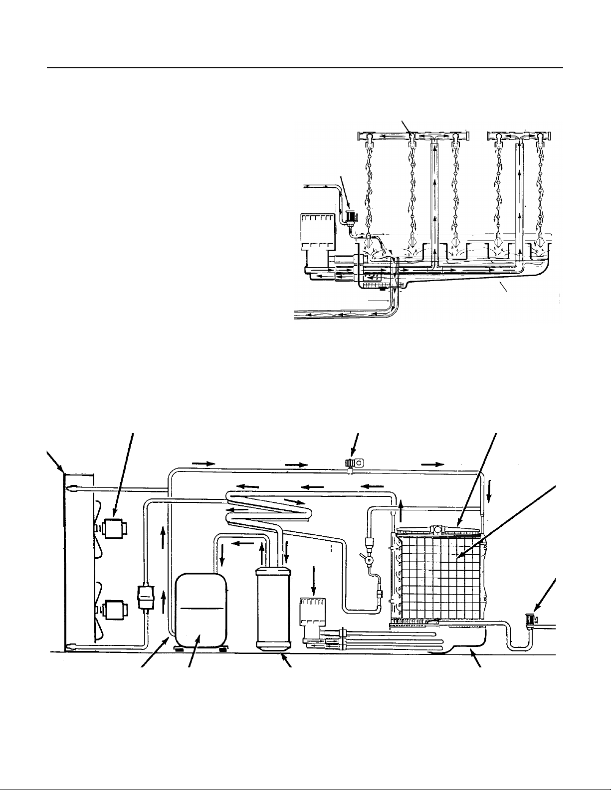
HARVEST CYCLE - HOT GAS BYPASS
WATER
INLET
VALVE
DISCHARGE
LINE
When the timer switches the icemaker into the
harvest cycle, the finish relay is de-energized, and
the hot gas valve and inlet water valve OPEN.
Then high pressure, high temperature gas
refrigerant being discharged from the compressor
is diverted from the condenser through the hot gas
solenoid valve into each evaporator plate. During
this cycle, the refrigerant bypasses the condenser.
Both the compressor and the water pump are
operating.
The finished ice cubes are released from the sides
of each evaporator plate by the warming effect of
the hot gas condensing in each evaporator plate
and the water cascading over the ice cubes. The
released ice cubes drop into the ice storage bin
below. At the end of the harvest cycle, the timer
cam will push in the microswitch actuator arm. If
there is no ice close to the bin level control’s
transducer, a whole new cycle will begin. If there is
ice within 8" of the base of the machine (when the
bin level control is set for full) the icemaker will
shut OFF.
INLET
WATER
VALVE
WATER
DISTRIBUTION
DRAIN
WATER SCHEMATIC
CMS1202
RESERVOIR
CONDENSER
FAN MOTOR
COMPRESSOR
HOT GAS VALVE
WATER
PUMP
ACCUMULATOR
REFRIGERATION SCHEMATIC
WATER
MANIFOLD
EVAPORATOR
RESERVOIR
September 1993
Page 11
Page 12
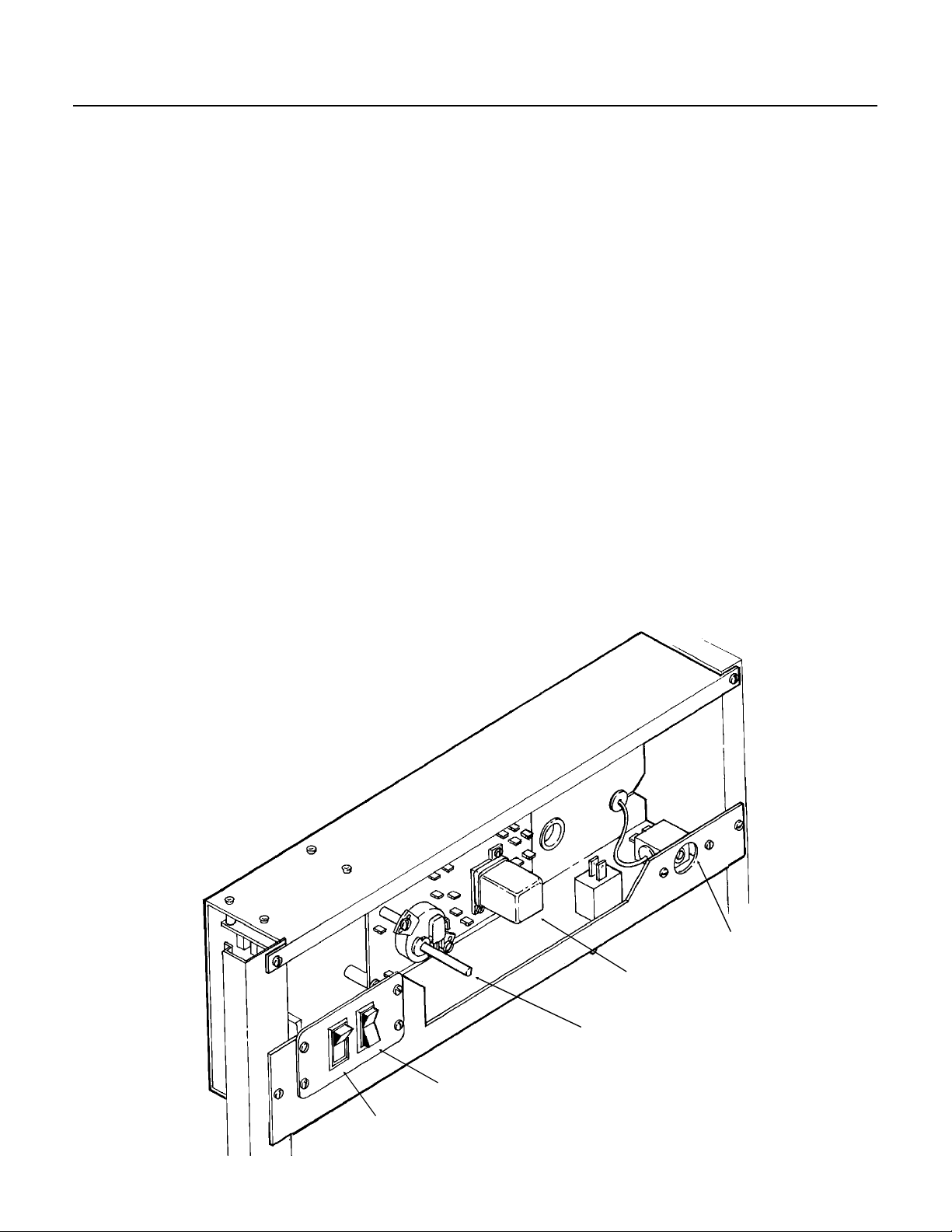
CMS1202
COMPONENT DESCRIPTION
Cube Size Control
This reverse acting thermostat controls the length
of the freezing cycle. It is sensing the temperature
of the suction line. When the suction line gets cold
enough, the cube size control closes (on
temperature fall) and starts the timer. A change in
either ambient air or incoming water temperature
will affect the efficiency of the refrigeration system,
and this will vary the length of time it takes the
evaporator to reach the temperature at which the
cube size control is preset to close. See CUBE
SIZE ADJUSTMENT BEFORE attempting to
adJust the control.
Relay
The multi-function, three pole, double throw,
plug-in relay is inserted into a receptacle on the
printed circuit board in the control box. The relay
functions in part to by-pass the bin thermostat
control to prevent the icemaker from shutting OFF,
when the bin thermostat opens during the freezing
cycle. The bypass action serves to ensure
full-sized ice cubes with each harvest cycle and,
to prevent short cycling on the bin thermostat
control.
Timer - Timer & Switch Assembly
The timer cam is controlled by the cube size
control. The outer surface, or large diameter lobe
of the timer cam, determines the timer cycle for
finish freezing of the ice cubes, while the inner
surface, or small diameter lobe, determines the
time cycle for the harvest cycle.
When the microswitch button is pushed in there is
power connected to the coil of the relay, and the
unit is in the freeze cycle. When the microswitch
button is released, the power to the relay is
stopped, and the unit goes into harvest. The
microswitch is actuated by a cam assembly
directly connected to the timer motor.
One complete rotation of the cam will take eight
minutes. Harvest is preset at two and one fourth
minutes, but is adjustable.
High Pressure Safety Control
This is a manual reset control that shuts down the
icemaker, should the discharge pressure ever
reach 450 PSIG on air cooled and 350 PSIG on
water cooled. Found below the control box.
CONTROL BOX
CUBE SIZE
CONTROL
RELAY
TIMER AND
MICROSWITCH
ICE/OFF/WASH
SWITCH
BIN ICE LEVEL
SELECTOR SWITCH
September 1993
Page 12
Page 13
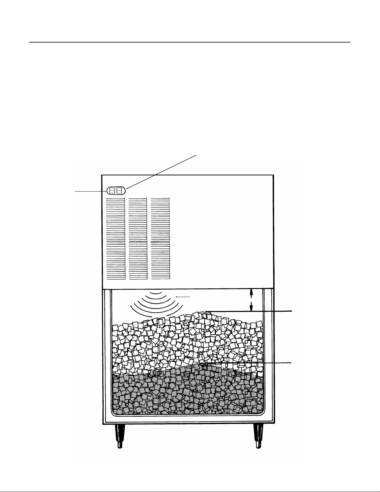
COMPONENT DESCRIPTION
THE USER CAN
SELECT THE
AMOUNT OF ICE TO
BE MAINTAINED IN
THE BIN.
Bin Level Control
CMS1202
This electronic control uses sound waves to
measure the distance between the bottom of the
ice machine and the top of the ice in the bin. It is
designed to control the machine’s ice production to
maintain that distance.
The control is adjustable so that the ice machine
will maintain a certain height of ice. When set at
FULL it will not allow the machine to fill the bin any
closer to the ice machine than about 8", and it will
not work if the distance to the bottom of the bin is
greater than 8 feet.
BIN ICE
LEVEL
SELECTOR
SWITCH
Because it uses sound waves, a slight “ticking”
sound can be heard coming from the bottom of the
machine.
There are two parts to the control, the circuit
board, and the level control switch.
ICE/OFF/WASH SWITCH
SOUND WAVES
FULL
PARTIAL
September 1993
Page 13
Page 14
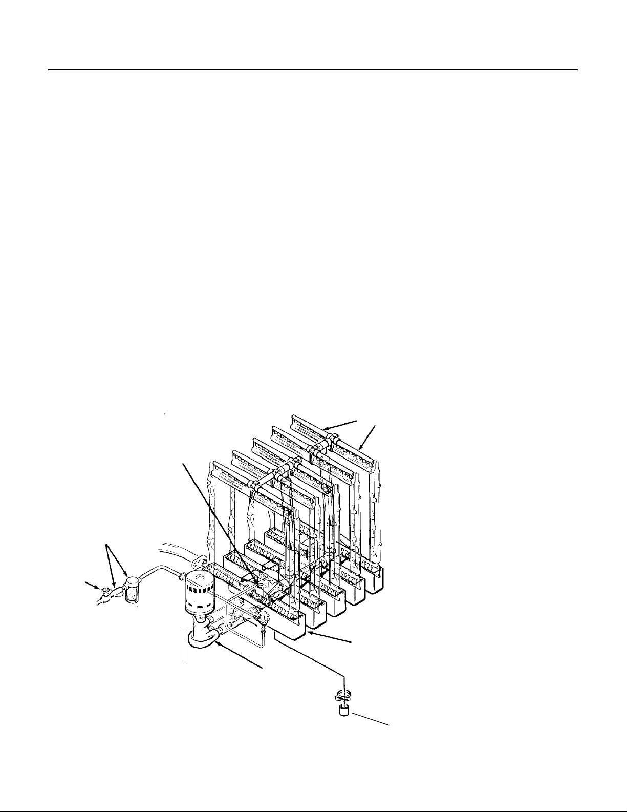
CMS1202
COMPONENT DESCRIPTION
Water Inlet Solenoid Valve
The water inlet solenoid valve fills the sump
assembly with water. Extra water overflows out the
overflow standpipe of the sump. This action fills
and rinses the sump during each harvest cycle.
The flow rate is 1 g.p.m.
Water Regulator Valve - Water Cooled Model
The water regulator valve maintains a constant
compressor head pressure, by regulating the
amount of inlet water flow through the condenser
on water cooled models. The valve operates
through the refrigerant system high side pressure.
Rotating the adjusting screw, located on top of the
valve, can INCREASE or DECREASE the water
flow through the water cooled condenser, which in
turn, will DECREASE or INCREASE the
compressor operating head pressure. lt is to be set
at 220 PSIG. When installing a replacement water
regulator valve, be sure the replacement valve is
installed with the arrow positioned in the direction
of the water flow.
Water Distribution System
The water distribution system functions to evenly
supply water to all cells of the evaporator plates.
The water pump pumps water from the sump up
the vertical tygon tube to the tee. From there water
is channeled through the water manifold to the
water distributors, above each evaporator plate,
and from six holes within each distributor, water
flows to the cells of each side of the evaporator
plates. Gravity flow returns the unfrozen excess
portion of water to the sump reservoir for
recirculation.
Hot Gas Solenoid Valve
The hot gas solenoid valve opens only during the
harvest cycle, to divert the hot discharge gas from
the compressor, by passing the condenser and
capillary tube, for direct flow to the evaporator
plates to release ice cubes from the ice cube
molds.
Fan Pressure Control - Air-Cooled Models only.
OPTIONAL
WATER FILTER
HAND
VALVE
SUMP STANDPIPE
PUMP
WATER
DISTRIBUTORS
SUMP
ln both freeze and harvest
cycles, the fan pressure
control functions to
maintain a minimum
discharge pressure by
cycling the fan on and off.
The approximate C.I. is
210 PSIG and C.O. is 193
PSIG.
Strainer
A water strainer is located
in the potable inlet water
line before the water inlet
solenoid valve. Clean the
water strainer frequently.
COMPONENT LOCATION
September 1993
DRAIN CAP
Page 14
Page 15
CMS1202
CLEANING
/////////////////////////////////////////////////////////////////////////////////////////////////////////////////////////////////////////////////////////////
A Scotsman Ice System represents a sizable investment of time and money in any company’s business. In
order to receive the best return for that investment, it MUST receive periodic maintenance.
Maintenance and Cleaning should be scheduled at a minimum of twice per year.
/////////////////////////////////////////////////////////////////////////////////////////////////////////////////////////////////////////////////////////////
CLEANING: ICEMAKER
1. Remove screws and the front panel.
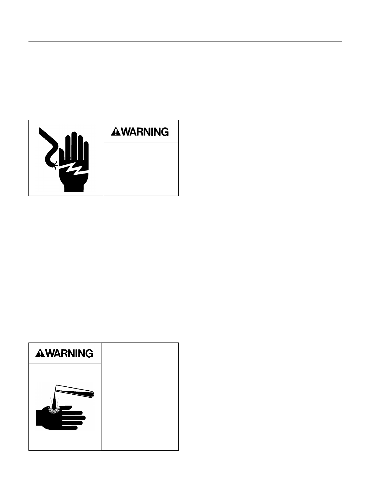
2. Switch the compressor switch to OFF. Switch
Electrical Shock
Hazard.
Electrical shock can
cause personal injury.
Cleaning procedures are
done with the power ON.
the WASH/OFF/ICE switch to OFF.
3. Remove the control box cover, and rotate the
shaft of the timer and switch assembly
CLOCKWISE advancing to the freezing cycle.
(Beginning of the higher part of the cam against
the microswitch).
4. Open the ice storage bin door and empty the bin
of ice.
5. Remove the hose clamp, rubber cap and drain
all the water from the sump assembly into a
container.
Replace the rubber cap and hose clamp.
7. Pour the cleaning solution into the reservoir until
full.
8. Move the WASH/OFF/ICE switch to the WASH
position.
9. Let the unit operate for 30 minutes.
During the wash cycle, if the machine runs out of
solution, mix 2 more gallons of solution per step 6,
refill the sump and continue the wash cycle for the
remainder of the 30 minutes.
10. Move the WASH/OFF/ICE switch to the OFF
position.
11. Remove the reservoir drain cap and drain the
cleaning solution from the sump. Replace the drain
cap.
12. Rotate the shaft of the timer and switch
assembly CLOCKWISE to the harvest position
(low part of the cam against microswitch). Move
the WASH/OFF/ICE switch to the ICE position to
start the Harvest cycle.
If, after completing this procedure, one or more
evaporator plates does not have a full flow of water
for each vertical column of cubes, shut down the
operation and remove and clean all water
distributor manifolds. Reinstall the water distributor
manifolds.
6. Mix 24 ounces of Scotsman Ice Machine
Cleaner with 2 gallons of warm (95
water.
Scotsman Ice Machine
Cleaner contains acids.
These compounds may
cause burns.
If swallowed, DO NOT
induce vomiting. Give
large amounts of water
or milk. Call Physician
immediately. In case of
external contact, flush
with water.
KEEP OUT OF THE
REACH OF CHILDREN.
0
F. - 1150F.)
Note: Thie ice making portion of the water system
should be sanitized after cleaning by repeating
steps 2-12, except substitute an approved
sanitizing solution for the cleaning solution.
13. Move the compressor ON-OFF switch to the
ON position to start the icemaking process.
////////////////////////////////CAUTION//////////////////////////////////
DO NOT use ice produced from the cleaning
solution. Be sure none remains in the bin.
///////////////////////////////////////////////////////////////////////////////////
14. Check the next ice cube harvest to be sure that
the ice cubes are clear and the acid taste is gone.
15. Add hot water to the bin to melt the ice.
16. Replace all panels.
September 1993
Page 15
Page 16
CMS1202
CLEANING
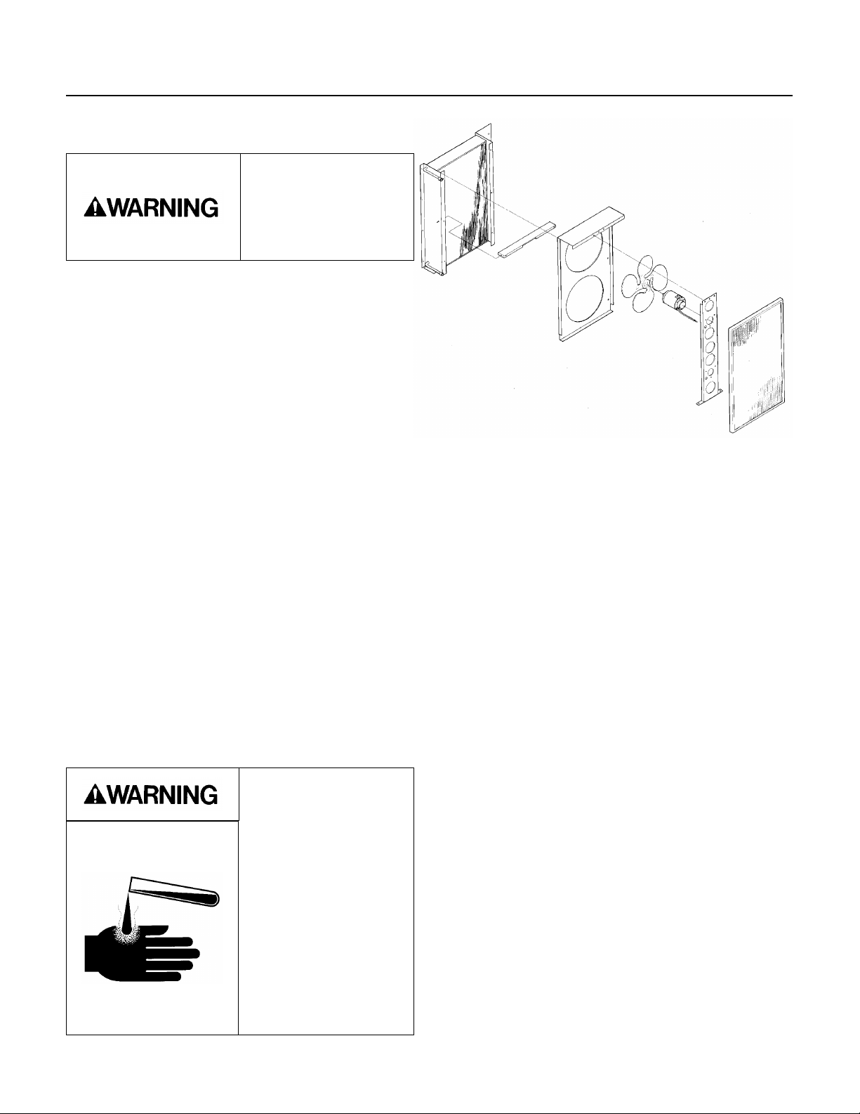
AIR COOLED CONDENSER
1. Disconnect electrical power.
The fan blade can
cause personal injury.
Disconnect power
before begining to clean
condenser.
2. Remove front panel.
3. Clean or replace the air filter.
4. Check to see that the inside of the condenser is
clean; light should be visible through the fins. If not
clean the internal parts by vacuum, pressure
washer and/or coil cleaner.
ICE STORAGE BIN
The interior liner of the bin is in contact with a food
product: ice. The storage bin must be cleaned
regularly to maintain a sanitary environment.
Once a week cleaning with soap and water, a hot
water rinse and an air dry is a basic procedure.
Scale that may form on the plastic liner can be
removed by scrubbing the surface with a mixture
of Scotsman Ice Machine Cleaner and hot water.
Remove any scale prior to sanitizing.
Note: Some ice storage bins have stainless steel
liners. They may become stained from chlorine
gases released from the water. These stains must
be removed by regular cleaning to prevent pitting
of the metal liner. To prevent the staining, an
activated charcoal water filter should be added to
the ice machine’s incoming water supply line;
activated charcoal removes the chlorine. This may
require more frequent sanitation.
Scotsman Ice Machine
Cleaner contains
acids. These
compounds may
cause burns.
If swallowed, DO NOT
induce vomiting. Give
large amounts of water
or milk. Call Physician
immediately. In case of
external contact, flush
with water.
KEEP OUT OF THE
REACH OF CHILDREN.
CLEANING
CONDENSER
To Remove Scale:
1. Mix a cleaning solution of 4 ounces of Scotsman
Ice Machine Cleaner to 4 pints of hot (95
0
110
F.) water.
2. Using rubber gloves, dip a nylon scouring pad
into the cleaning solution, and scrub the scale off
of the liner.
3. After all the scale has been removed, rinse all of
the surfaces inside the bin with clean, potable
water.
To sanitize the bin and ice machine interior.
Use an approved sanitizer and follow the
directions and warnings of that sanitizer or use the
following instructions for use of household bleach,
if it meets local codes:
1. Mix a sanitizing solution of 1 ounce of
household bleach to 2 gallons of water.
2. Using clean rubber gloves and a clean cloth,
wipe all interior surfaces of the ice machine and
ice storage bin with the santizing solution.
Immerse any small parts in the sanitizing solution
and wash the parts, flushing the solution
thoroughly in, over and through all parts and
surfaces of the parts being cleaned.
3. Allow to air dry.
AIR COOLED
CONDENSER
MUST BE
CLEAN
0
F. to
FILTER
September 1993
Page 16
Page 17
ADJUSTMENTS
CMS1202
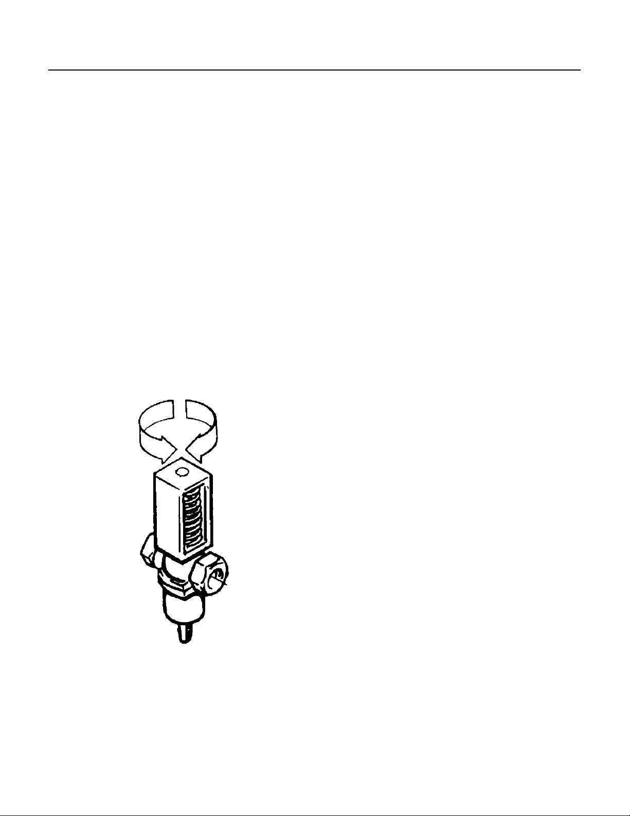
Adjustment Of The Water Regulator Assembly -
Water-cooled Models
The correct compressor head pressure on water
cooled models is 220 PSIG. Adjusting the water
regulator valve increases or decreases the rate of
flow of water, through the water cooled condenser;
which increases or decreases the affected
temperature/pressure of the compressor head
pressure, INCREASED water flow, results in
DECREASED or LOWER head pressure; while,
DECREASED water flow, results in INCREASED
or Higher head pressure.
To adjust the water regulator assembly:
To INCREASE the head pressure, rotate the
adjusting screw COUNTER Clockwise.
To DECREASE the head pressure, rotate the
adjusting screw Clockwise. Check change in
compressor head pressure, and repeat adjustment
as necessary, to achieve desired operating head
pressure.
Adjustment Of The Cube Size Control
//////////////////////////////CAUTION////////////////////////////////////
BEFORE adjusting the cube size control, check
other possible causes for cube size problems,
refer to Service Diagnosis section. DO NOT
perform adjustment when a new cube size control
is installed until the control bulb has been properly
installed in the tube well, and the icemaker has
been through a complete freezing and harvest
cycle.
///////////////////////////////////////////////////////////////////////////////
Adjustment of the cube size control is available to
change the cubes to the correct size, see INITIAL
START UP.
To produce LARGER sized ice cubes:
1. Locate the cube size control, on the front of the
control box.
2. Rotate the adjusting knob one-eighth of a turn
Clockwise.
3. Observe size of ice cubes in next ice cube
harvest and, if needed, repeat step 2 above until
correct ice cube size is achieved.
ADJUSTMENT OF THE WATER
REGULATING VALVE
To produce SMALLER sized ice cubes:
1. Locate the cube size control, on the front of the
control box.
2. Rotate the adjusting knob one-eighth of a turn
COUNTER Clockwise.
3. Observe size of ice cubes in next ice cube
harvest and, if needed, adjust again until correct
ice cube size is achieved.
September 1993
Page 17
Page 18
CMS1202
ADJUSTMENTS
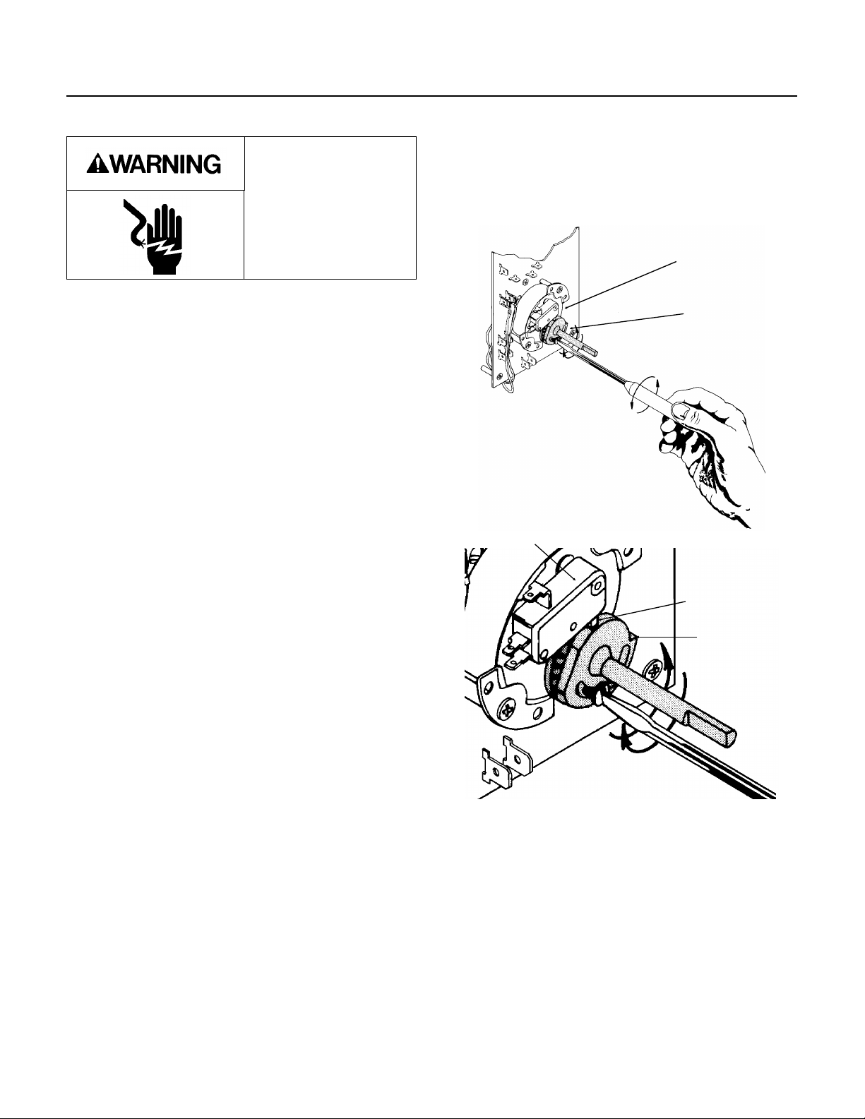
Adjustment Of The Timer & Switch Assembly
Electrcial power present
in the control box can
cause personal injury.
Disconnect power
before begining to
adjust timer.
One complete revolution of the cam on the timer
takes eight minutes. The normal setting is two and
one-quarter minutes, as set at the factory. lt is
important that the length of the harvest cycle allow
enough time for all the ice cubes to fall from the
evaporator. Too short of a time will cause the
evaporator to freeze up and stop ejecting ice into
the bin. Too much time wastes icemaking capacity,
energy and water. Adjustment of the harvest cycle
may require a corresponding adjustment of the
cube size control. Rotating the shaft of the timer
cam clockwise will allow putting the machine into
either the freezing cycle or harvest cycle, as
required in the cleaning instructions.
To Adjust The Timer & Switch Assembly:
The length of the harvest cycle can be changed by
loosening the set screw on the cam, and then
rotating the shaft so that the opening between the
cams change. More of an opening between the
cams = more harvest time.
TIMER
CAM
ADJUSTING TIMER
MICROSWITCH
CLOSE UP
VIEW OF TIMER
SWITCH
ACTUATOR
CAM
September 1993
Page 18
Page 19

CMS1202
SYSTEM SPECIFICATIONS
The following numbers can be used as a guideline when servicing the CMS1202. There will be some
variation from unit to unit, so allow for that.
COMPONENTS:
Timer, 1 revolution of the cam takes 8 minutes, harvest time is factory set at 3
Inlet water valve, water flow in g.p.m. = 1
CUT IN CUT OUT
0
Cube size control, reverse acting temperature range . . . . . . . (0
High pressure safety, (air cooled) . . . . . . . . . . . . . . . . . . Manual 450
High pressure safety, (water cooled) . . . . . . . . . . . . . . . . Manual 350
Fan Pressure Switch . . . . . . . . . . . . . . . . . . . . . . . 210 193
Bin or Ice level Control
Maximum Full Height: . . . . . . . . . . . . . . . . . . . . 8" from the base of the ice machine.
Partial Fill Setting: . . . . . . . . . . . . . . . . . . . . . . 21" - 22" from the base of the ice machine.
Maximum Storage Bin Interior Height: . . . . . . . . . . . 8’ from the base of the ice machine
F. to +250F.)
1
⁄2 minutes, but is adjustable.
CHARACTERISTICS: This machine uses R22.
AIR COOLED
Freeze cycle
Average Discharge Pressure at: 90
Average Suction Pressure at the end of Freeze: . . . . . . . . . . 22-20 PSIG
Average Freeze cycle time . . . . . . . . . . . . . . . . . . . . . 17 minutes
Average Amps . . . . . . . . . . . . . . . . . . . . . . . . . . . 13 (single phase ) 7.8 (3 phase)
Harvest Cycle
Average Discharge Pressure at: 90
Average Suction Pressure during harvest . . . . . . . . . . . . . 70-75 PSIG
Average Harvest Time: . . . . . . . . . . . . . . . . . . . . . . . 2.25 minutes
Average Amps . . . . . . . . . . . . . . . . . . . . . . . . . . . 19 (single phase)
WATER COOLED
Freeze cycle
Average Discharge Pressure at: 90
Average Suction Pressure at the end of Freeze: . . . . . . . . . . 20-2
Average Freeze cycle time . . . . . . . . . . . . . . . . . . . . . 17
Average Amps . . . . . . . . . . . . . . . . . . . . . . . . . . . 10 (single phase) 7 (three phase)
0
/700 . . . . . . . . . . . . . . 280-240 PSIG
0
/700 . . . . . . . . . . . . . 120-130 PSIG
0
/700 . . . . . . . . . . . . . . 225
Harvest Cycle
Average Discharge Pressure at: 900/700 . . . . . . . . . . . . . . 120-130 PSIG
Average Suction Pressure during harvest . . . . . . . . . . . . . 75-85 PSIG
Average Harvest Time: . . . . . . . . . . . . . . . . . . . . . . . 2.25 minutes
Average Amps . . . . . . . . . . . . . . . . . . . . . . . . . . . 16 (single phase)
September 1993
Page 19
Page 20
CMS1202
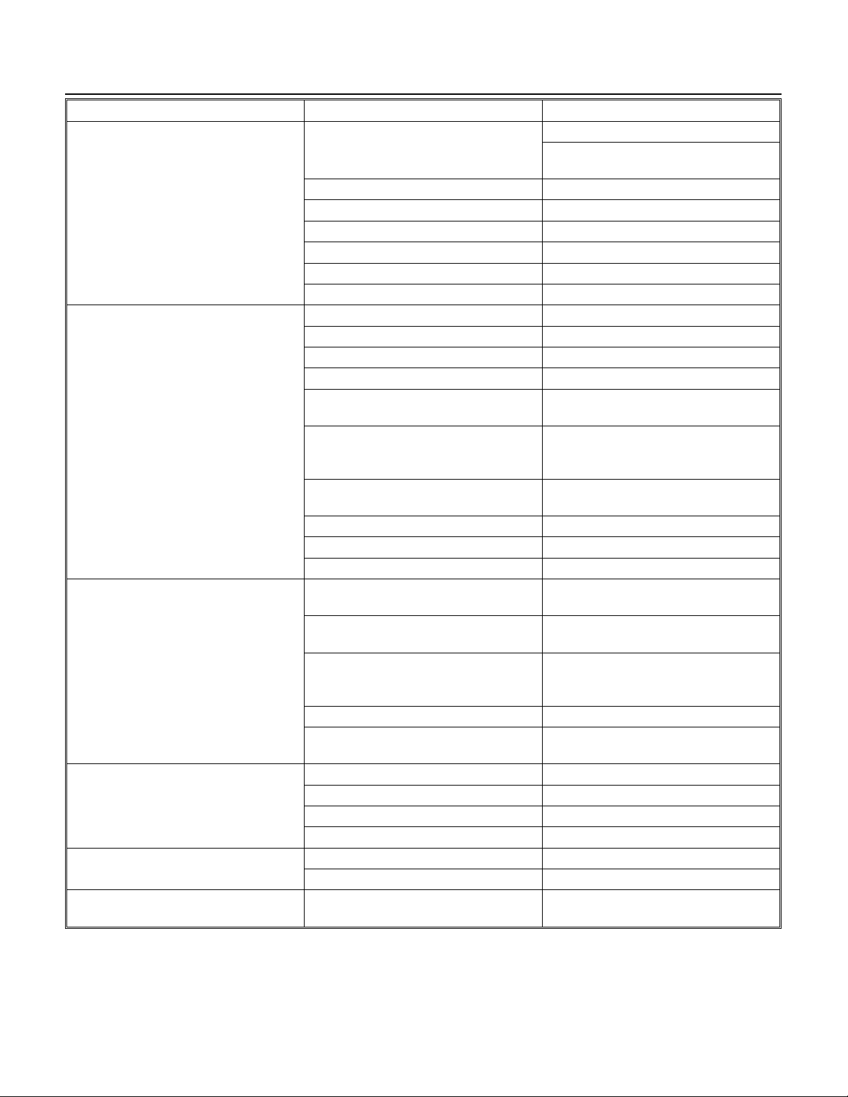
SERVICE DIAGNOSIS: Electrical and/or Adjustments
SYMPTOM POSSIBLE CAUSE PROBABLE FIX
Nothing operates Bin level control holding machine off Bin is full - use some ice.
Check ice level control circuit, see
page 22.
No Power Reconnect power
High pressure control open Reset, check machine
High temperature cut out open Hot gas valve leaks thru, replace
P. C. Board Open Replace board
Master switch open Test/replace
Timer contacts open Replace timer
Makes thick ice/freezes up Harvest cycle too short Adjust timer
Water inlet valve restricted Clean or replace valve
Low water pressure Check water filter or supply
Hot gas valve defective Replace hot gas valve
Water reg. valve (water cooled) leaks
through
Low refrigerant charge Locate leak, repair, replace drier,
Air intake temperature too high (air
cooled)
Sump covers out of position Re-position sump covers
Cubes too small Adjust cube size
Cube size control stuck open Replace cube size control
Runs, makes no ice Pump problem or water leak in
reservoir
Water inlet valve either lets in no
water or leaks through
Low refrigerant charge Locate leak, repair, replace drier,
Timer stuck Replace timer
Relay does not energize; unit stuck in
harvest
Long freeze cycle Water inlet valve leaks through Replace inlet water valve
Dirty condenser Clean condenser
Air intake temp. too high Reduce room temperature
Water temperature too high Advise user
Cubes too small Cube size set wrong adjust cube size
Cubes size control stuck closed Replace cube size control
Cubes too large Water inlet valve leaks through Replace inlet water valve and adjust
Replace water reg. valve
evacuate and weigh in nameplate
charge.
Reduce room temperature
Check water system and pump
Replace inlet water valve
evacuate and weigh in nameplate
charge.
Replace relay
cube size control
September 1993
Page 20
Page 21
CMS1202
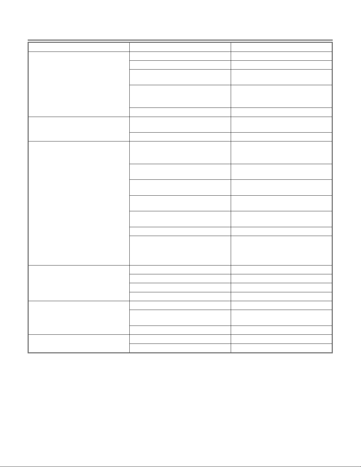
SERVICE DIAGNOSIS: Refrigeration and/or Mechanical
SYMPTOM POSSIBLE CAUSE PROBABLE FIX
Poor harvest Too short harvest time Check and adjust harvest time
Restriction of incoming water Check supply, filter, strainer and valve
Hot gas valve does not open Check for power to the coil, check for
not opening, replace
Not enough refrigerant Locate leak, repair, replace drier,
evacuate and weigh in nameplate
charge.
Cube size too small Adjust with cube size control
Unit cycles off during freeze or
harvest
Low capacity High head pressure, from dirty
Unit runs out of water Reservoir leaks Repair leak
Unit shuts off before bin is full Something blocking transducer Remove blockage
Unit does not shut off Ice level control failiure Check circuit, see next page.
Hi temperature switch opens and
closes
Loose connection on PC board Check and replace P C board
condenser, faulty fan motor, or fan
control
Non condensable gas in the system Purge system, evacuate and weigh in
Poor air circulation or extreme hot
location
Overcharge of refrigerant Evacuate and weigh in nameplate
Cube size too big, unit runs out of
water before harvest
Inlet water valve leaks thru Replace valve
Hot gas valve leaks thru At the end of the freeze cycle there
Inlet water valve restricted Clean or replace valve
Short harvest cycle Adjust timer
Water pressure too low Check supply
Transducer is wet Remove transducerand shake screen
Control set on partial Set control to full.
Timer stuck; does not turn Replace timer
Hot gas valve leaks thru, replace it
Clean condenser, repair fan motor or
control
nameplate charge
Relocate the cabinet; or provide
ventilation
charge
Adjust cube size control
should be frost on the evaporator end
of the hot gas tubes, if not replace the
hot gas valve
dry.
September 1993
Page 21
Page 22
Electrical Shock Hazard
Can Cause Personal Injury.
Disconnect Power Before
Servicing.
Bin Thermostat Posts at
Line Voltage.
CMS1202
SERVICE DIAGNOSIS: Ice Level Control Circuit
CONDITION DETERMINE CAUSE PROBABLE CORRECTION
Ice Machine does not run, it has
power to it, the high pressure control
is closed, the on/off switch is set to
ON.
Machine runs, makes ice, switches
on and off, but ice level cannot be
controlled.
Machine runs, but will not shut off. Board relay stuck closed. Check
A. Listen for a ticking sound from
transducer.
B. Open bin door and twist
transducer 1/4 turn and pull out. DO
NOT UNPLUG with power
connected. Examine the transducer,
the inside must be clean and dry.
C. Check power to bin level control
board.
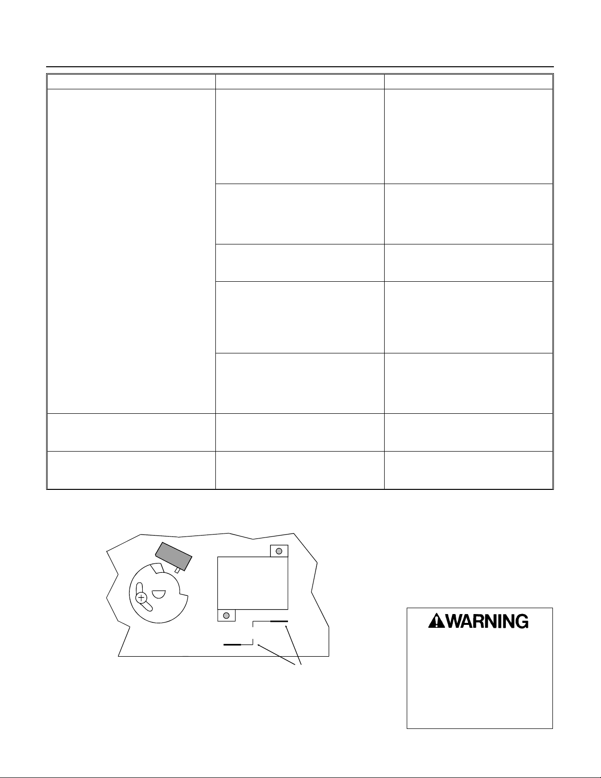
D. Disconnect electrical power and
test ice machine circuit by attaching a
jumper wire between bin thermostat
posts on circuit board part no.
12-1912-01 (the circuit board with the
timer on it). Reconnect power.
E. Transducer or ice level board
assembly defective.
Ice level switch may be defective. On
boards with a light, check by moving
switch & watching light.
relay.
If no noise, go to C. If there is a
noise, check for a light on the board
(models built after 4/93). If there is a
light on, check relay contacts N.O.
and COM. The contacts should be
CLOSED. If closed, go to D. If not,
replace the board. If light is off, or
prior model, go to B.
If the inside of the transducer (above
screen) was wet, replace it. Set bin
level to FULL and aim at an object
about 1-3 feet away. Machine should
restart, if not go to D.
Should be 12 volts from transformer,
if not replace transformer. If there is
power go to D.
If machine does not start go back to
machine circuit. If machine starts,
disconnect electrical power, remove
jumper wire and reconnect electrical
power. Then go to E.
Replace transducer. Set bin level to
FULL and aim at an object about 1-3
feet away. Machine should restart. If
this does not repair unit, replace the
board.
Replace ice level switch
If COM and N.O. are closed when
power is off, replace board. If open,
go to B above.
PARTIAL VIEW OF
CIRCUIT BOARD
12-1912-01
TIMER
PLUG - IN
RELAY
BIN THERMOSTAT
POSTS MENTIONED
IN “D” ABOVE
September 1993
Page 22
Page 23
REMOVAL AND REPLACEMENT
CMS1202
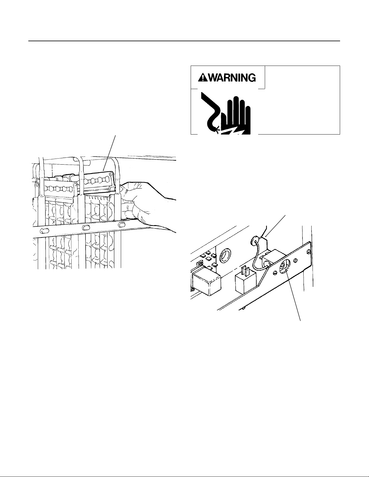
Water Distributor Tubes And Manifold Tubes
To remove the water distributor tube and manifold
tube:
1. Remove the front panel.
2. Slide the water distributor tube to the front about
1/8-inch along the top of the evaporator plate, until
the water distributor tube can be unsnapped from
the flexible notch and lifted upward.
DISTRIBUTOR TUBE
Cube Size Control
To remove the cube size control:
Electrical Shock
Hazard.
Electrical shock can
cause personal injury.
Disconnect power
before begining to
service components
1. Remove front panel.
2. Remove cover from control box.
3. Trace capillary tube, from the cube size control
to the refrigerant suction line.
4. Remove the coiled capillary tube bulb from the
tube well on the suction line.
5. Remove electrical leads from the cube size
control.
NOTCH IN CONTROL
BOX
3. Unsnap and disconnect water distributor tubes
from the water manifold section. To replace the
water distributor tubes and manifold tubes, reverse
the removal procedure. BE SURE the notches in
the water manifold tubes properly engage the
alignment keys in the tee. BE SURE the water
distributor tube is securely fastened at the notch at
both sides of the evaporator plate. Check identical
attachment for the left water distributor tube and
notch; also, that the distributor/manifold
connections at the top center of each evaporator
plate is snug against the top of the plate.
September 1993
REMOVAL OF THE
CUBE SIZE CONTROL
6. Remove screws and pull the capillary tube
through the notch in the back of the control box.
Remove the cube size control. To replace the cube
size control, reverse the removal procedure.
Page 23
CUBE SIZE
CONTROL
Page 24
CMS1202
REMOVAL AND REPLACEMENT
Electrical Shock
Hazard.
Electrical shock can
cause personal injury.
Disconnect power before
begining to service
components
Water Pump
1. Remove front panel.
2. Unplug water pump electrical connection.
3. Drain water reservoir.
4. Use corbin clamp pliers to loosen and slide
corbin clamps on hoses away from pump.
5. Remove screws retaining pump to bracket.
6. Pull pump out of ice machine.
7. Reverse to reassemble.
8. Replace front panel.
8. Reconnect electrical power.
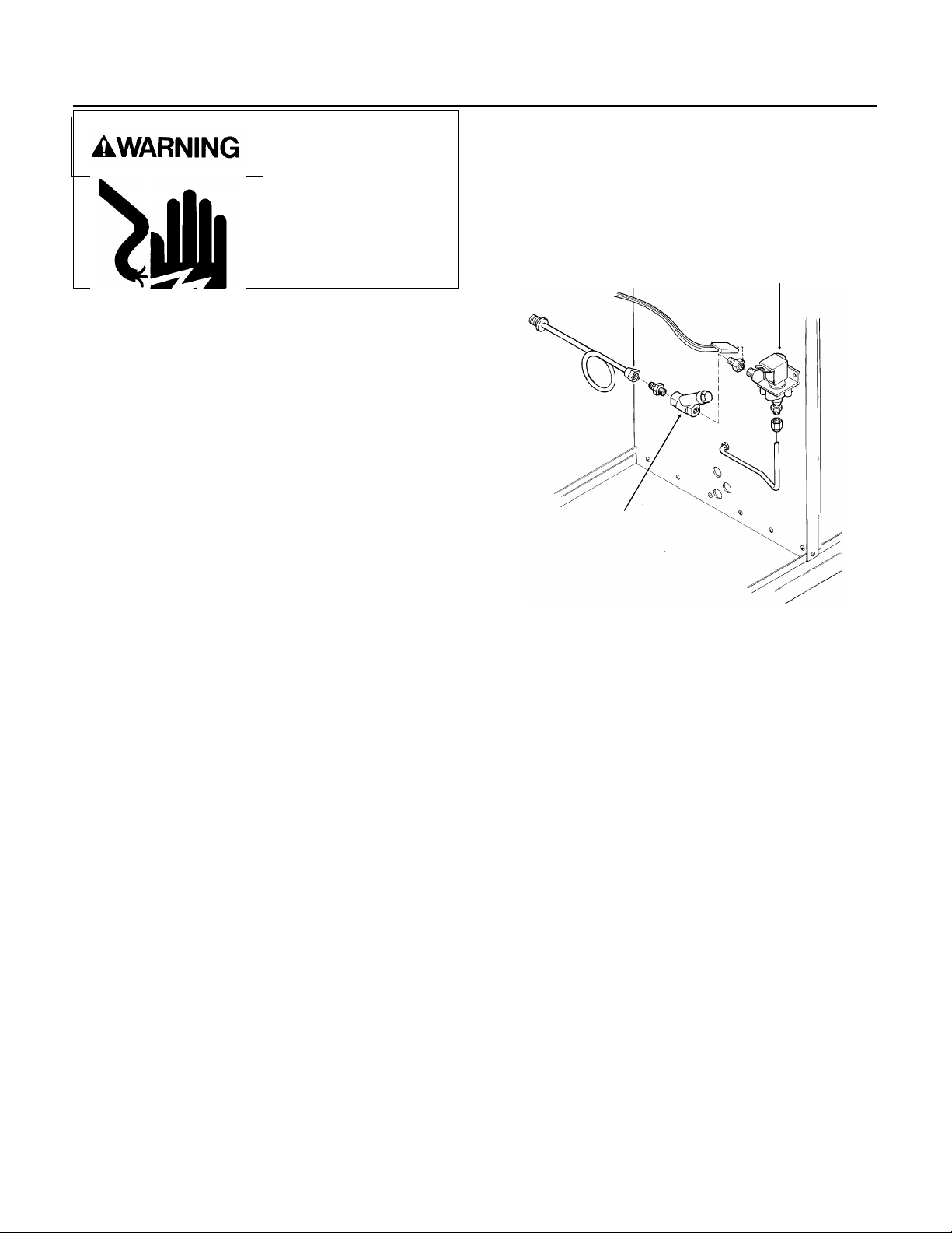
Inlet Water Solenoid Valve Assembly
To remove the inlet water solenoid valve assembly:
1. Shut OFF water supply to machine.
2. Loosen and remove outlet water line from the
inlet water solenoid valve assembly.
INLET WATER VALVE
STRAINER
Transducer
1. Disconnect electrical power BEFORE removing
transducer.
2. Remove front panel, and locate transducer near
the back of the cabinet.
3. Twist inner portion of transducer
counter-clockwise and pull up gently.
4. Unplug transducer and remove from the
machine.
5. Reverse steps 1-5 to reassemble.
3. Remove screws and pull the water solenoid
valve out to gain access.
4. Pull electrical cord from solenoid coil terminals.
5. Remove inlet water fitting from the water
solenoid valve. To replace the inlet water valve
assembly, reverse the removal procedures.
Bin Ice Level Control Circuit Board
1. Disconnect Electrical Power before removing
circuit board.
2. Remove front panel.
3. Remove control box cover.
4. Remove wires from circuit board connections.
5. Unlock circuit board fasteners by twisting 1/2
turn.
6. Pull circuit board of off fastener posts.
7. Reverse to reassemble, refer to wiring diagram
as needed.
September 1993
Page 24
 Loading...