

Page 1

Statim 7000
Field Training Manual
Page 2

Table of Contents
Table of Contents 2
Packaging & Accessories 3
Installation 4 – 6
User Setup 7 – 12
Service Setup 13 – 22
Cover Removal 23 – 25
Armature Removal 26
Rear Cover Removal 27
Chassis Parts 28 – 30
Cassette 31 – 33
Error Codes 34 – 38
Water Conductivity Circuit Calibration 39
Validation Thermocouple Calibration 40 – 41
2
Page 3
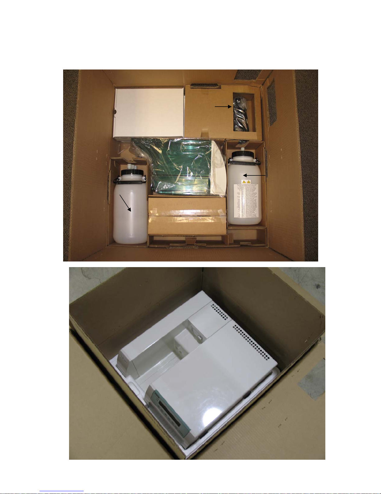
Packaging & Accessories
Exhaust Tubings
Stat-Dri Power Cord
Op Manual
O-ring Lube
Cassette (on bottom of box)
Condenser Bottle
Statim 7000
Water Reservoir
2 Water Filters
Waste Bottle
3
Page 4
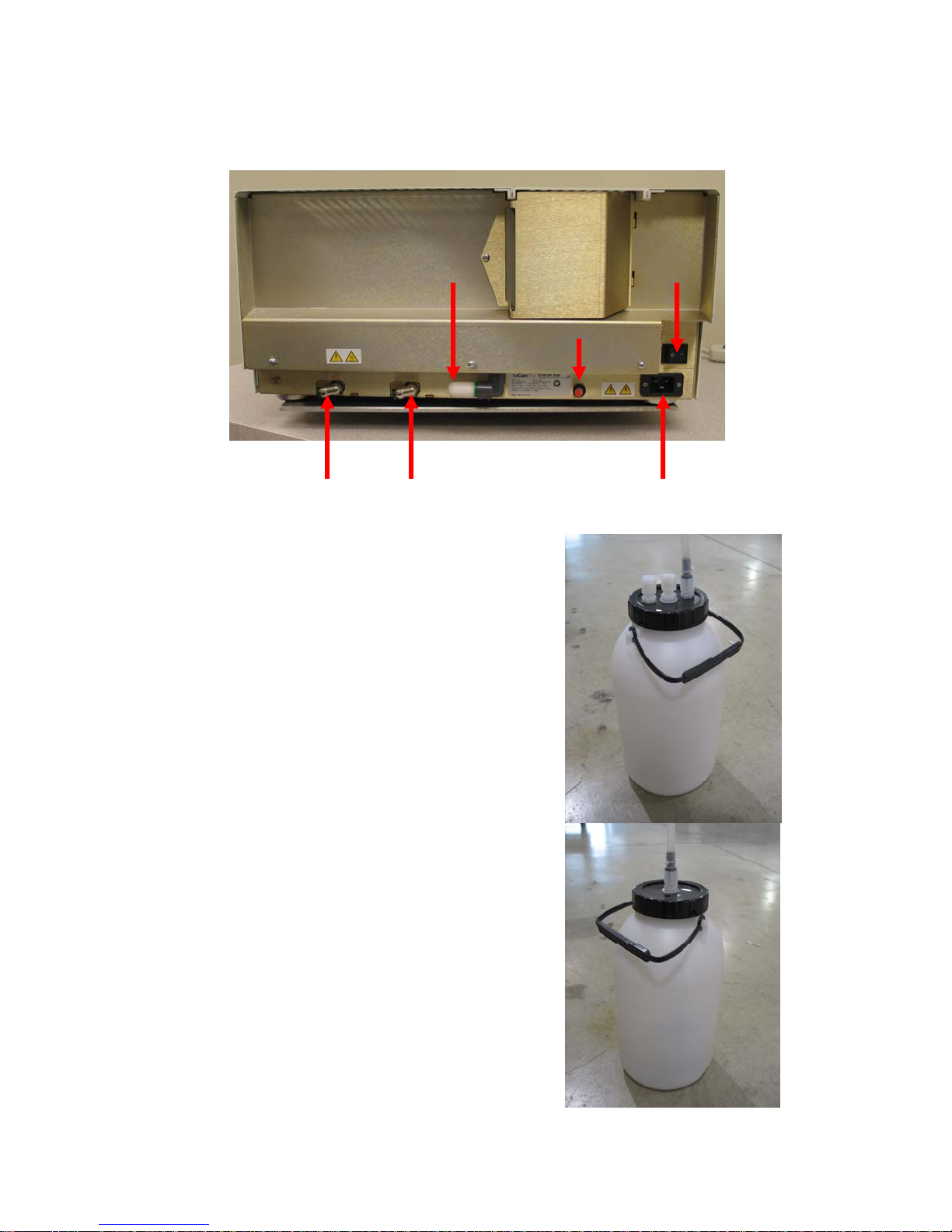
Statim 7000 Installation
Connect the Power Cord and the Exhaust Tubings to the rear of the Statim.
Push In Fitting Push In Fitting Power Cord Connection
Connect the Exhaust Tubings to the large fittings
on the Condenser Bottle & the small tubings to the
small fitting on the Condenser & Waste Bottles.
Drain Tube
Power Switch Air Filter
Condenser Bottle
Waste Bottle
4
Page 5
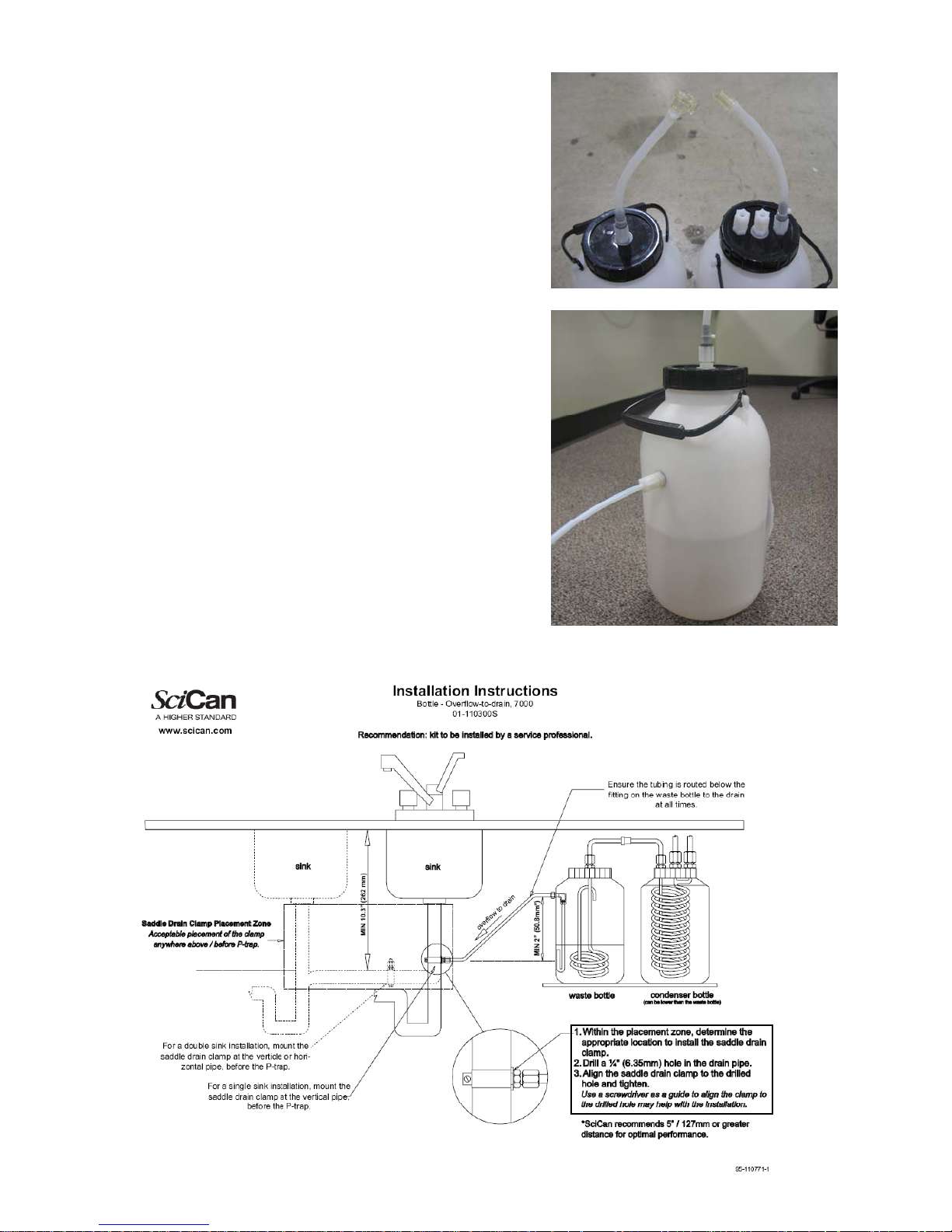
Connect bottle together using Quick Disconnect
Coupling.
Direct to Drain Waste Bottle
Direct to Drain Waste Bottle Installation Instructions
5
Page 6
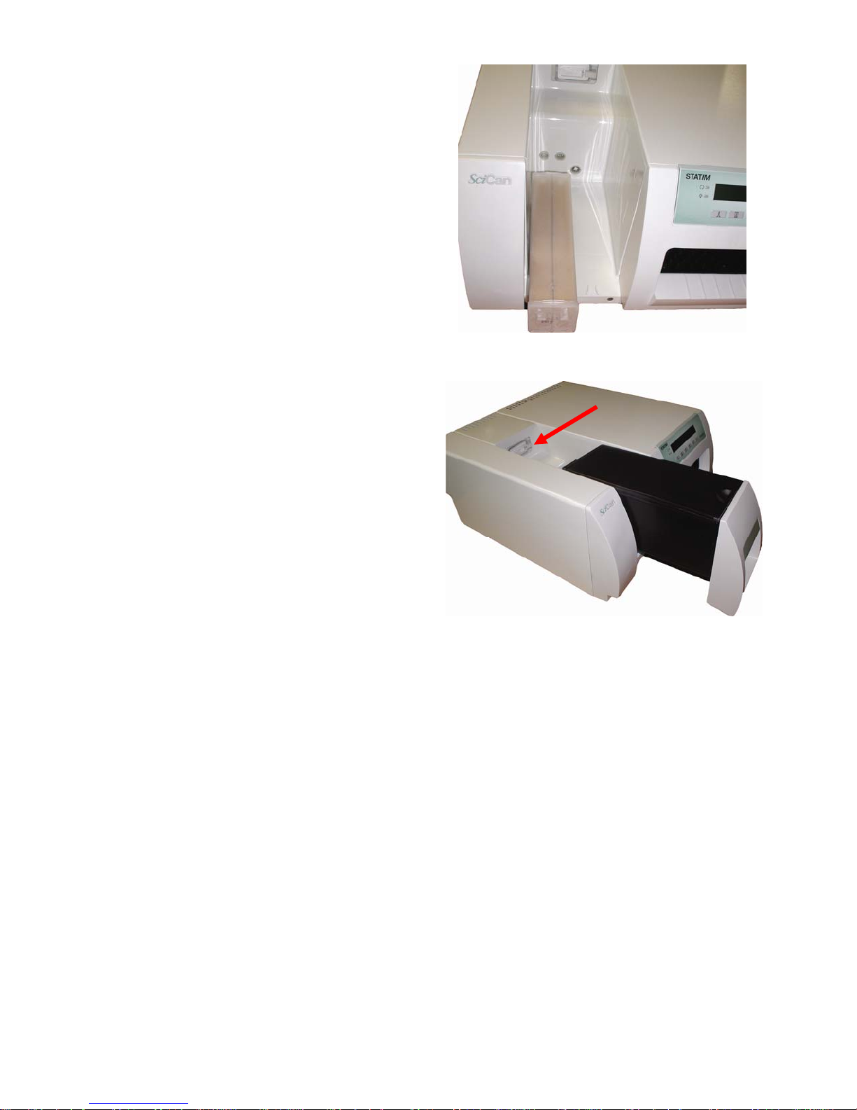
Insert Water Filter or Bypass Cartridge.
Insert Water Reservoir
Note: The Biological Filter is accessible behind the Water Reservoir.
Biological Filter
6
Page 7
Statim 7000 User Setup
User setup mode – To initially setup your Statim
Hold down the Stop button and turn the unit ON.
If unit is already ON.
Hold down the Stop Button and the Air Dry Only Button simultaneously.
Initial Display
>Time/Date Setup
Language Setup
Unit ID Setup *
Drying – Unwrapped
Drying – Wrapped
Drying – R&P
Drying - Extra
Water Quality
Last Printout *
RS232 *
End of Line CR/LF *
Serial Port Bit rate *
Printer user º char *
Steri. End buzzer
Air Filter Warning
Water Filter
Replace Filter
Save and Exit
Exit
* Only used when Statim is connected to a Printer or Data Logger
Keypad:
Unwrapped Select next item in the menu
Wrapped Select previous item in the menu
Rubber and Plastics Enter the indicated sub menu selection
Stop Exit menu to normal mode of operation
Time/Date Setup Mode – Set the proper time and date
Keypad:
Unwrapped Increase current field (the flashing value on the display)
Wrapped Decrease current field (the flashing value on the display)
Rubber and Plastics Select next field
Stop Save & exit menu to normal mode of operation
18:00 04/10/2008
HH:MM MM/DD/YYYY
7
Page 8

Language Setup – Display information in your desired language
N. A. ENGLISH
Available Languages
N. A. English (North American English)
U. K. English (United Kingdom English)
Francais (French)
Deutsch (German)
Espanol (Spanish)
Italiano (Italian)
Dansk (Danish)
Portugues
Nederlands
Japanese
Svenska (Swedish)
Polski (Polish)
Magyar (Hungarian)
Cesky (Czech)
Norsk (Norwegian)
Islenska (Iceland)
Slovencina (Slovak)
Eesti (Estonian)
Lietuviu K. (Lithuanian)
Slovenian (Slovenia)
Romana (Romanian)
Keypad:
Unwrapped Select next language
Wrapped Select previous language
Stop Save & exit menu to normal mode of operation
Unit ID Setup – Associate unit with an ID number (Used with Printer)
Keypad:
Unwrapped Decrease current field (the flashing value on the display)
Wrapped Increase current field (the flashing value on the display)
Rubber and Plastics Select next digit
Stop Save & exit menu to normal mode of operation
Unit # :
000
8
Page 9

Drying – Unwrapped – Set Unwrapped Cycle drying time between 0 & 30 minutes
Keypad:
Unwrapped Increase time by one minute
Wrapped Decrease time by one minute
Rubber and Plastics Save and return to main menu
Stop Save & exit menu to normal mode of operation
>Drying - Unwrapped
Time: 12 minutes
Drying – Wrapped – Set Wrapped Cycle drying time between 10 & 30 minutes
Keypad:
Unwrapped Increase time by one minute
Wrapped Decrease time by one minute
Rubber and Plastics Save and return to main menu
Stop Save & exit menu to normal mode of operation
>Drying - Wrapped
Time: 12 minutes
Drying – R&P – Set Rubber & Plastics Cycle drying time between 0 & 30 minutes
Keypad:
Unwrapped Increase time by one minute
Wrapped Decrease time by one minute
Rubber and Plastics Save and return to main menu
Stop Save & exit menu to normal mode of operation
>Drying – R&P
Time: 12 minutes
Drying – Extra – Sets drying time between 1 & 30 minutes for Air Dryer Only Cycle
Keypad:
Unwrapped Increase time by one minute
Wrapped Decrease time by one minute
Rubber and Plastics Save and return to main menu
Stop Save & exit menu to normal mode of operation
>Drying – Extra
Time: 12 minutes
9
Page 10

Water Quality – Display detected water quality
>Water quality
CD= x.xuS/NNN/y.yppm
Screen Representation
x.x Water conductivity in uS (micro-Siemens)
NNN Water conductivity in ADC (Analog to Digital converter) counts (0…255)
y.y Water quality in ppm (parts per million)
Keypad:
Rubber and Plastics Return to main menu
Stop Exit menu to normal mode of operation
Last Printout – Printer reprints last cycle and unit returns to normal mode of operation
(Used with Printer)
RS232 – To select which serial device to attach (Used with Printer)
Serial Printer
Keypad:
Unwrapped Move to next option, second line shows the new value
Wrapped Move to previous option, second line shows the new value
Rubber and Plastics Save and return to main menu
Stop Exit menu to normal mode of operation without saving
>RS232
N/A
USB FLASH/MSD
End of Line CR/LF – Configure the printout layout (Used with Printer)
Available options:
- No line terminator is sent after each line. To be used with printer that accepts only
CR A <CR> is sent at the end of the line. To be used with printers that advance to
CR/LF A <CR><LF> is sent at the end of the line. To be used with printers that translate
Keypad:
Unwrapped Select next option. Second line shows the new value
Wrapped Select previous option. Second line shows the new value
Rubber and Plastics Save & exit to main menu
Stop Exit and return to normal mode of operation
>End Of Line CR/LF
CR/LF
CR
This only needs to be set if a serial printer is attached to the serial port.
20 characters per line and automatically advances to next line. Should be used
with the STATprinter.
beginning of next line when a CR is received.
advance to beginning of next line only when LF is received.
10
Page 11
SciCan Suggested
[
External Printers
Epson
End Of Line
CR/LF
Serial Port Bit
Rate
Printer user ° char
CR/LF 9600 248 [0xF8]
TM-U220D (C31C515603)
Citizen
CR 9600 N/A
IDP-3110-40 RF 120B
Star Micro
CR 9600 210 [0xd2]
SP212FD42-120
Star Micro
CR/LF 9600 210 [0xd2]
SP216FD41-120
Star Micro
CR/LF 9600 210 [0xd2]
SP512MD42-R
Serial Port Bit Rate – Choose bit rate for device connected to the serial port
(Used with Printer)
Serial Port Bit Rate
9600
19200
57600
115200
1200
2400
4800
If USB FLASH/MSD is selected as the RS232 device, a Serial Port Bit Rate selection of 9600 will
be required for the Data Logger to be operational.
Keypad:
Unwrapped Select next value
Wrapped Select previous value
Rubber and Plastics Save & Return to main menu
Stop Exit without saving and return to normal mode of operation
Printer user ° char – Setting to print a °C sign (Used with Printer)
32 decimal value for selected char-default 32
20 hex value for the selected char-default 20
Keypad:
Unwrapped Increase value by one
Wrapped Increase value by ten
Rubber and Plastics Select and return to main menu
Stop Exit without saving and return to normal mode of operation
Printer user ° char
0x20]
32
11
Page 12

Steri. End buzzer – Set length of time buzzer will sound a end of sterilization
15s
30s
Max
Keypad:
Unwrapped Select next value
Wrapped Select previous value
Rubber and Plastics Save & Return to main menu
Stop Save & exit menu to normal mode of operation
>Steri. End buzzer
0s
Air Filter Warning – Reset warning indicator when Air Filter is replaced.
Yes, Reset
>Air Filter Warning
Do not Reset
Water Filter – Set Statim for Water Filter or Water Bypass Cartridge
Not Installed
>Water Filter
Installed
Replace Filter – Reset Statim when Water Filter is replaced.
Yes, replace
>Replace Filter
Do not replace
Save and Exit
Upon selection, current settings are saved and unit restarts in normal mode of operation
– Saving settings and return to normal mode of operation
Exit – Exit menu without saving settings
Upon selection, current settings are discarded, not saved and unit restarts in normal mode of
operation
12
Page 13

Statim 7000 Service Setup
Service setup mode – To enter the Service Setup Mode, turn power switch ON while
holding down Unwrapped and Wrapped buttons.
The Service Setup Mode is password protected; a password must be entered to continue. The
default password is Unwrapped, Wrapped, Rubber and Plastics, Stop buttons pressed in this
order. If the password has been changed the backdoor password is, Unwrapped, Wrapped,
Unwrapped, Wrapped buttons pressed in this order.
* Only used when Statim is connected to a Printer or Data Logger
Keypad:
Unwrapped Select next item in the menu
Wrapped Select previous item in the menu
Rubber and Plastics Enter the indicated sub menu selection
Stop Exit menu to normal mode of operation
>Calibration
Time/Date Setup
Language Setup
Unit ID Setup *
Set cycle counter
Conductivity Setup
Water.Cnd Tmp. Comp
Last Printout *
Stored CF Printouts *
Clear CF Printouts *
Display last CF#
Devices Test On/Off
Temperature Offset
Validation Offset
Repeater mode
RS232 *
End of Line CR/LF *
Serial Port Bitrate *
Printer user º char *
Factory default
Drying – Unwrapped
Drying – Wrapped
Drying – R&P
Drying - Extra
Air Filter Warning
Water Filter
Replace Filter
Steri. End buzzer
Upgrade Firmware
Change Password
Backup NVRAM
Restore NVRAM
Save and Exit
Exit
Production Cycle
13
Page 14

Calibration – Select calibration to run chamber and validation thermocouple calibration cycles
only.
Note: See page 38 for validation thermocouple calibration procedure.
Time/Date Setup Mode – Set the proper time and date
Keypad:
Unwrapped Increase current field (the flashing value on the display)
Wrapped Decrease current field (the flashing value on the display)
Rubber and Plastics Select next field
Stop Save & exit menu to normal mode of operation
18:00 07/09/2008
HH:MM MM/DD/YYYY
Language Setup – Display information in your desired language
Available Languages
N. A. English (North American English)
U. K. English (United Kingdom English)
Francais (French)
Deutsch (German)
Espanol (Spanish)
Italiano (Italian)
Dansk (Danish)
Portugues
Nederlands
Japanese
Svenska (Swedish)
Polski (Polish)
Magyar (Hungarian)
Cesky (Czech)
Norsk (Norwegian)
Islenska (Iceland)
Slovencina (Slovak)
Eesti (Estonian)
Lietuviu K. (Lativan)
Keypad:
Unwrapped Select next language
Wrapped Select previous language
Rubber and Plastics If Repeater mode is ON, this key will scroll through all the available
Stop Save & exit menu to normal mode of operation
N. A. ENGLISH
Slovenian (Slovenia)
Romana (Romanian)
display messages of the chosen language.
14
Page 15

Unit ID Setup – Associate unit with an ID number (Used with Printer)
Unit # :
000
Keypad:
Unwrapped Decrease current field (the flashing value on the display)
Wrapped Increase current field (the flashing value on the display)
Rubber and Plastics Select next digit
Stop Save & exit menu to normal mode of operation
Set cycle counter – Adjust the recorded number of cycles ran
Cycle Number
000000
Keypad:
Unwrapped Decrease current digit
Wrapped Increase current digit
Rubber and Plastics Select next digit
Stop Save & exit menu to normal mode of operation
Conductivity Setup – To display detected water quality and adjust low and high thresholds.
CD= x.xuS/NNN/y.yppm
L R H=HH.H G=G.GG
Screen Representation
x.x Water conductivity in uS (micro-Siemens)
NNN Water conductivity in ADC (Analog to Digital converter) counts (0…255)
y.y Water quality in ppm (parts per million)
L “L” is displayed when water level switch is activated, "-" when the switch is
R “R” is displayed when water reservoir reed switch is activated, "-" when the
HH.H High value threshold (Bad water threshold) default 10uS
Values larger than this trigger “Bad water quality” error
G.GG Water conductivity circuit gain default 1.00
Note: Statim 7000 does not use the conductivity reading to trigger the “No Water, Refill
Reservoir” message. There is a float sensor for that.
Keypad:
Unwrapped Increase current field
Wrapped Decrease current field
Rubber and Plastics Move to next field
Stop Exit menu to normal mode of operation
Note: To perform Water Conductivity Circuit Calibration see page 37.
not active
water reservoir reed switch is not activated.
15
Page 16

Water Cnd Tmp Comp - To enable or disable water conductivity temperature compensation
Off
Keypad:
Unwrapped Select next option Second line shows the new value
Wrapped Select previous option. Second line shows the new value
Rubber and Plastics Select and return to main menu
Stop Exit, without saving, to normal mode of operation
>Water Cnd Tmp Comp
On
Last Printout – Printer reprints last cycle and unit returns to normal mode of operation
(Used with Printer)
Stored CF Printouts – Printer prints saved cycle fault printouts and unit returns to normal
mode of operation. (Used with Printer)
The saved CF printouts are sent to the printer or data logger only when either one is attached and
configured. The following types of errors are saved:
CF’s
Water quality or Water level low errors
Cycle interrupted due to errors (##)
Clear CF Printouts – Reset Cycle Fault printout list (Used with Printer)
Yes
Keypad:
Unwrapped Select next option Second line shows the new value
Wrapped Select previous option. Second line shows the new value
Rubber and Plastics Select and return to main menu
Stop Exit, without saving, to normal mode of operation
>Clear CF Printouts
No
Display last CF# - Show the last Cycle Fault that occurred
Screen Representation
## Last recorded CF number
(######) Cycle counter number for last CF
Keypad:
Rubber and Plastics Return to main menu
Stop Exit to normal mode of operation
>Display last CF#
## (######)
16
Page 17

Devices Test On/Off – Toggle the unit’s devices on or off
>Devices Test On/Off
Pump Off
Valve Off
Compressor Off
Yellow LED Off
Extra 1L Off
Extra 2L Off
Valve 2 Off
Fan Off
Keypad:
Unwrapped Select next option. Second line shows the new value
Wrapped Select previous option. Second line shows the new value
Rubber and Plastics Toggle On/Off selected device
Stop Return to main menu
Chamber Temperature Offset – View the offset of the chamber thermocouple
>Temperature Offset
##
Screen Representation
## Offset value
Keypad:
Rubber and Plastics Return to main menu
Stop Exit to normal mode of operation
Validation Offset – View the offset of the validation thermocouple
Screen Representation
>Validation Offset
##
## Offset value
Keypad:
Rubber and Plastics Return to main menu
Stop Exit to normal mode of operation
Repeater mode – Enable or disable unit to run cycles continuously
On
Keypad:
Unwrapped Select next option. Second line shows new value
Wrapped Select previous option. Second line shows new value
Rubber and Plastics Select and return to main menu
Stop Exit, without saving, to normal mode of operation
>Repeater mode
Off
17
Page 18

RS232 – To select which serial device to attach (Used with Printer)
>RS232
N/A
Serial Printer
USB FLASH/MSD
Keypad:
Unwrapped Move to next option, second line shows the new value
Wrapped Move to previous option, second line shows the new value
Rubber and Plastics Save and return to main menu
Stop Exit menu to normal mode of operation without saving
End of Line CR/LF – Configure the printout layout (Used with Printer)
This only needs to be set if a serial printer is attached to the serial port.
Available options:
- No line terminator is sent after each line. To be used with printer that accepts only
20 characters per line and automatically advances to next line. Should be used
with the STATprinter.
CR A <CR> is sent at the end of the line. To be used with printers that advance to
beginning of next line when a CR is received.
CR/LF A <CR><LF> is sent at the end of the line. To be used with printers that translate
advance to beginning of next line only when LF is received.
Keypad:
Unwrapped Select next option. Second line shows the new value
Wrapped Select previous option. Second line shows the new value
Rubber and Plastics Save & exit to main menu
Stop Exit and return to normal mode of operation
SciCan Suggested
External Printers
Epson
TM-U220D (C31C515603)
Citizen
IDP-3110-40 RF 120B
Star Micro
SP212FD42-120
Star Micro
SP216FD41-120
Star Micro
SP512MD42-R
>End Of Line CR/LF
CR/LF
CR
End Of Line
CR/LF
CR/LF 9600 248 [0xF8]
CR 9600 N/A
CR 9600 210 [0xd2]
CR/LF 9600 210 [0xd2]
CR/LF 9600 210 [0xd2]
Serial Port Bit
Rate
Printer user ° char
18
Page 19

Serial Port Bit Rate – Choose bit rate for device connected to the serial port
(Used with Printer)
If USB FLASH/MSD is selected as the RS232 device, a Serial Port Bit Rate selection of 9600 will
be required for the Data Logger to be operational.
Keypad:
Unwrapped Select next value
Wrapped Select previous value
Rubber and Plastics Save & return to main menu
Stop Exit, without saving, and return to normal mode of operation
Serial Port Bit Rate
9600
19200
57600
115200
1200
2400
4800
Printer user ° char – Setting to print a °C sign (Used with Printer)
dd decimal value for selected char-default 32
hh hex value for the selected char-default 20
Keypad:
Unwrapped Increase value by one
Wrapped Increase value by ten
Rubber and Plastics Select and return to main menu
Stop Exit, without saving, and return to normal mode of operation
Printer user ° char
dd [0xhh]
Factory default – Reset to factory default settings
Yes, Reset NVRAM!
This function resets the NVRAM to factory default settings. The chamber and voltage calibration
offsets and conductivity settings will be reset. The cycle counter will not be reset.
Keypad:
Unwrapped Select next option. Second line shows the new value
Wrapped Select previous option. Second line shows the new value
Rubber and Plastics Save and return to main menu
Stop Exit, without saving, and return to normal mode of operation
>Factory default
No
19
Page 20

Drying – Unwrapped – Set Unwrapped Cycle drying time between 0 & 30 minutes
Keypad:
Unwrapped Increase time by one minute
Wrapped Decrease time by one minute
Rubber and Plastics Save and return to main menu
Stop Save & exit menu to normal mode of operation
>Drying - Unwrapped
Time: 12 minutes
Drying – Wrapped – Set Wrapped Cycle drying time between 10 & 30 minutes
Keypad:
Unwrapped Increase time by one minute
Wrapped Decrease time by one minute
Rubber and Plastics Save and return to main menu
Stop Save & exit menu to normal mode of operation
>Drying - Wrapped
Time: 12 minutes
Drying – R&P – Set Rubber & Plastics Cycle drying time between 0 & 30 minutes
Keypad:
Unwrapped Increase time by one minute
Wrapped Decrease time by one minute
Rubber and Plastics Save and return to main menu
Stop Save & exit menu to normal mode of operation
>Drying – R&P
Time: 12 minutes
Drying – Extra – Sets drying time between 1 & 30 minutes for Air Dryer Only Cycle
Keypad:
Unwrapped Increase time by one minute
Wrapped Decrease time by one minute
Rubber and Plastics Save and return to main menu
Stop Save & exit menu to normal mode of operation
>Drying – Extra
Time: 12 minutes
20
Page 21

Air Filter Warning – Reset warning indicator when Air Filter is replaced.
>Air Filter Warning
Do not Reset
Yes, Reset
Water Filter – Set Statim for Water Filter or Water Bypass Cartridge
>Water Filter
Installed
Not Installed
Replace Filter – Reset Statim when Water Filter is replaced.
>Replace Filter
Do not replace
Yes, replace
Steri. End buzzer – Set length of time buzzer will sound a end of sterilization
15s
30s
Max
>Steri. End buzzer
0s
Upgrade Firmware – Not used at this time.
Change Password – Change the password required to access the service menu
The unit will query for a 4 key password
Type New Password
****
The unit will require that the user re-enter the same 4 key password
Type New Password
****
The unit will confirm that the password has been changed or if changing the
password failed, the unit will again query for a new 4 key password
Password Changed
In case the changed password is lost a backdoor password can be used: Unwrapped, Wrapped,
Unwrapped, Wrapped in this order.
21
Page 22

Backup NVRAM – Saves a copy of the unit’s current settings
Yes
Keypad:
Unwrapped Select next option Second line shows the new value
Wrapped Select previous option. Second line shows the new value
Rubber and Plastics Select and return to main menu
Stop Exit, without saving, to normal mode of operation
>Backup NVRAM
No
Restore NVRAM – Restores the previously saved unit settings into the NVRAM
Yes
Keypad:
Unwrapped Select next option Second line shows the new value
Wrapped Select previous option. Second line shows the new value
Rubber and Plastics Select and return to main menu
Stop Exit, without saving, to normal mode of operation
>Restore NVRAM
No
Save and Exit – Saving settings and return to normal mode of operation
Upon selection, current settings are saved and unit restarts in normal mode of operation
Exit – Exit menu without saving settings
Upon selection, current settings are discarded, not saved and unit restarts in normal mode of
operation
Production Cycle – For manufacturing use only
22
Page 23

1. With the unit off, unplug the power
cord from the wall outlet and remove
the cassette and reservoir from the
unit.
Statim 7000 Cover Removal
2. Remove the water filter or water bypass
cartridge (if the unit is using distilled
water) from the reservoir area.
3. Remove the eight screws across the
bottom front of the unit using a Philips
screw driver.
4. Push the cover forward from the back
a little to loosen it, until it stops.
5. Detach the LCD/keypad by reaching
up inside the cover through the
armature opening to feel for a plastic
tab located directly behind the Rubber
and Plastics key.
23
Page 24

6. Push this tab to the left to unlock the
LCD/keypad from the cover.
7. Place the LCD/keypad on top of the
armature so that it is out of the way
as you remove the cover.
8. Release the cover retention clip by
reaching inside the cover though the
LCD opening and lift up on the tap
located on the left most side of the
opening. Slide cover forward.
24
Page 25

9. Push the cover all the way forward to
slide it off from the front.
10. To replace the cover. Place the cover
back on to the unit about 1 inch away
from the back. Once the chassis hooks
engage with the cover, push the cover
towards the back until the back of the
cover is in line with the back of the
chassis
11. Replace the LCD panel
12. Insert the 8 screws that were originally
removed.
25
Page 26

Armature Removal
Removed 2 screws in lower left and right corners
of Armature and loosen alignment screw in top
center of Armature.
Armature is mounted on 2 rails which will allow
the Armature to slide easily. Slide Armature
forward and remove using two hands. There are
no connections to the Armature.
Armature Screw
Armature Alignment Screw
Armature Screw
26
Page 27

Rear Cover Removal
Remove 3 screws from bottom of rear cover.
Remove 3 screws from top of rear cover.
Disconnect black and white wires from Fan
Disconnect Biological Filter Tubings
Biological Filter Tubings
Screw Screw
Screw Screw
Fan Wires
Screw
Screw
27
Page 28

Statim 7000 Chassis Parts
Thermocouple Validation
Reservoir Inlet
01-110493S
01-110515S
Armature Microswitch
Biological Filter
01-102119S
Armature
01-110496S
01-110502S
PCB RFID Board
01-110483S
28
Page 29

Reservoir Inlet Assembly
01-110493S
Water Filter Ports
Water Reservoir Port
Sensor Reservoir
01-110492S
Compressor
01-110478S
Pump
01-110471S
29
Page 30

Solenoid Chamber
Valve 2
01-110527S
Push In Fitting
01-110503S
Plug Drain Tubing
Auxiliary Heater
01-104343S
01-110474S
Solenoid Validation
Valve 1
01-110528S
Line Filter
01-110505S
Boiler
01-110472S
Air Filter
01-101652S
Power Switch
01-110504S
30
Page 31

Perforated Rack
Statim 7000 Cassette
Steam Deflector
Outlet Coupling O-Ring Seals
Exhaust Duct
Exhaust Duct Screen
Outlet Coupling
Inlet Coupling
Inlet Coupling O-Ring Seals
31
Page 32

Cassette Complete 7000 Internal Dimensions:
Part #01-110288S 13.7" x 8.6" x 2.5"
Cassette Lid 7000
Part #01-110290S
Cassette Tray 7000
Part #01-110289S
Cassette Lid Handle
Part #01-110329S
Cassette Tray Handle
Part #01-110330S
Cassette Seal Kit (not shown)
Part #01-110327S
Cassette Inlet Coupling
Part #01-110291S
Cassette Outlet Coupling
Part #01-110292S
Cassette Coupling Seal Kit
Part #01-110296S
(Includes o-rings & gaskets for both couplings)
Cassette Perforated Rack
Part #01-110294S
Cassette Lid
Cassette Tray
Cassette Lid
Handle
Cassette Tray
Handle
Inlet Coupling
Outlet Coupling
Cassette Perforated
Rack
32
Page 33

Cassette Tray Exhaust Duct
Part #01-110297S
Cassette Steam Deflector
Part #01-110825S
Filter Exhaust Duct Insert
Part #01-106848S
Cassette Steam Deflector Clip
Part #01-110824S
Cassette Tray
Exhaust Duct
Cassette Steam
Deflector
Filter Exhaust
Duct Insert
Cassette Steam
Deflector Clip
33
Page 34

Statim 7000 Error Codes
Cycle Fault
Number
Cycle Fault #1 The Cassette temperature
Cycle Fault #3 The Cassette has failed to
Cycle Fault #4 The Cassette has failed to
Cycle Fault #6 The software has detected a
Cycle Fault #7 If chamber temperature drops
Cycle Fault #8 The software has detected a
Cycle Fault #10 The cassette temperature has
Cycle Fault #11 The cassette temperature has
Cycle Fault #12 This indicates a problem with
Description of Fault Suggested steps for Correction of Fault
failed to reach 95°C within a
time-out period.
pressurize and achieve a
temperature of 110°C within a
time-out period.
achieve sterilization
conditions within a timeout
period of the chamber first
reaching 110°C.
Validation Thermocouple
temperature 5°C greater than
the chamber during the
sterilizing phase of a cycle.
below the sterilization
temperature (134°/121°C) by
more than 3°C, CF 7 is
posted.
Validation Thermocouple
temperature 5° less than the
chamber during the sterilizing
phase of the cycle.
failed to drop to 115°C during
the Unwrapped or Wrapped
Cycle or 110°C during the
Rubber and Plastics Cycle in
the purge conditioning stage.
failed to drop to 102°C within
a timeout period during the
venting cycle.
the temperature measuring
system.
May be caused by a large cassette leak in
conjunction with an extremely large load or
a blown Thermal Fuse caused by weak
water pump delivery.
May be caused by a faulty Cassette Seal,
a damaged Cassette, or a faulty Solenoid
Valve (failed to close).
May be caused by a faulty Cassette Seal,
a damaged Cassette, or a faulty Solenoid
Valve (failed to close).
Check for kinked or pinched exhaust tubing
and for visible steam leaks from the
Cassette Seal, Lid or Tray. Check the
exhaust Solenoid Valves and make sure
the plunger is not sticking. Recalibrate
Validation Thermocouple.
May be caused by a faulty Cassette Seal,
a damaged Cassette, a faulty Solenoid
Valve (failed to close), a leaky Pressure
Relief Valve or a leaky Check Valve.
Check for a clogged Filter Screen in the
Exhaust Duct in the Cassette Tray. Check
the Solenoid Valves for debris and make
sure the plunger is not sticking. Recalibrate
the Validation Thermocouple.
Check for a clogged Filter Screen in the
Exhaust Duct in the Cassette Tray, a
kinked or pinched Exhaust Tubing from
center elbow fitting or a faulty Solenoid
Valve (failed to open).
Check for a clogged Filter Screen in the
Exhaust Duct in the Cassette Tray, a
kinked or pinched Exhaust Tubing from
center elbow fitting or a faulty Solenoid
Valve (failed to open).
Check for a disconnected, broken or faulty
thermocouple lead or a defective PCB.
34
Page 35

Cycle Fault #14 The steam temperature
raised above the high
threshold.
Cycle Fault #15 The cassette temperature
raised above the high
threshold during the
sterilization phase of the
cycle or above 138.6°C
during conditioning or
pressurizing phase of the
cycle.
Cycle Fault #16 The Boiler temperature
went above a threshold
value.
Cycle Fault #17 Auxiliary Heater
overheated.
Cycle Fault #18 Ambient temperature to
high.
Cycle Fault #19 The Validation
Thermocouple calibration is
invalid.
Cycle Fault #20 The cassette temperature
raised above 138.6°C
during the Drying phase of a
cycle.
Cycle Fault #25 The software has failed to
detect a need to pump
water within 90 seconds of
the state of a cycle.
Check for faulty PCB or defective Solid
State Relay.
Check for a clogged Filter Screen in the
Exhaust Duct in the Cassette Tray, a
kinked or pinched Exhaust Tubing from
center elbow fitting or a faulty Solenoid
Valve (failed to open).
Replace Water Filter
Check for a weak Water Pump or a faulty
PCB causing constant power to the Boiler.
Check for a faulty Auxiliary Heater, a
defective Solid State Relay or PCB.
Ambient temperature (as sensed by the
PCB cold junction temperature sensor)
increased over a preset threshold. This
may be caused by a failed cool down fan, a
failed Auxiliary Heater PCB or a defective
main PCB.
This occurs when a new PCB or
Microprocessor is installed. This may also
happen when the unit has been subjected
to a strong static discharge corrupting the
memory. Calibrate the Validation
Thermocouple.
Check for a clogged Filter Screen in the
Exhaust Duct in the Cassette Tray, a
kinked or pinched Exhaust Tubing leading
to the Condenser Bottle or a faulty
Solenoid Valve (failed to open). A faulty
Auxiliary Heater, Auxiliary Heater PCB or
Solid State Relay.
Check for a blown Thermal Fuse caused
by a weak Water Pump, constant power to
the Water Pump caused by a defective
PCB or a faulty Boiler.
35
Page 36

Cycle Fault #26 The sterilization phase has
failed to start within 3
minutes of the cassette
reaching sterilization
temperature.
CF26 is displayed when it
occurred in 3 consecutive
cycles (Cycle Interrupted is
displayed for the first two
cycles). CF26 counter is
reset whenever a
successful cycle is
completed.
Cycle Fault #27 The temperature of the
Boiler failed to drop below a
set-point temperature
(150°C) in a timeout period.
Cycle Fault #32 No water pumped to the
boiler while executing the
Water Filter priming.
Cycle Fault #79 Error in communication with
the RFID adapter or
Cassette Seal RFID tag.
Cycle Fault #80 Auxiliary Heater heating
element did not reach a
target temperature in a
specified period of time.
Cycle Fault #81 Auxiliary Heater
superheated steam did not
reach a target temperature
in a specified period of time.
Cycle Fault #82 Unit failed to cool down in a
specified period of time.
Cycle Fault #90 Corrupted or not initialized
chamber calibration value.
Cycle Fault #98 Main PCB not
communicating with
Auxiliary Heater PCB.
May be caused by improper Validation
Thermocouple calibration, weak Water
Pump or faulty Solenoid Valve.
May be caused by a weak Water Pump, a
defective float switch (does not detect
insufficient water in the water reservoir) or
a faulty Boiler.
May be leaking Water Filter, leaking Water
Reservoir connection or faulty Water
Pump.
Make sure cassette is completely inserted
and try another cycle.
May be defective Cassette Seal or RFID
adapter.
Check fuses on Auxiliary Heater PCB
May be a defective Auxiliary Heater,
Auxiliary Heater PCB, Solid State Relay or
main PCB.
Check to see that Biological Filter is
installed correctly.
Check fuses on Auxiliary Heater PCB
May be a defective Auxiliary Heater,
Auxiliary Heater PCB, Solid State Relay or
main PCB.
May be a defective Auxiliary Heater,
Auxiliary Heater PCB, Solid State Relay,
main PCB or Compressor.
This occurs when a new PCB or
Microprocessor is installed. This may also
happen when the unit has been subjected
to a strong static discharge corrupting the
memory. Unit requires chamber calibration.
May be Microprocessor not installed
properly, defective main PCB or Auxiliary
Heater PCB.
36
Page 37

“No
Configuration
EEPROM”
Message: Printer
No communication between
EEPROM and
Microprocessor.
Printer is not printing. Check for paper jam or defective Printer.
Fault (if optional
printer is
installed)
“Cycle Aborted” This error message is
displayed on the printout
only, followed by the
message “Not Sterile”, as a
result of the operator
pressing the STOP button
to stop the cycle or as a
result of any other abnormal
cycle termination, including
Cycle Fault errors.
“Stop Button
Pressed”
The operator pressed the
STOP button to stop the
cycle. The LCD shows the
message “Not Sterile”.
“ Cycle
Interrupted”
This message is displayed
when the sterilization phase
has failed to start within 3
minutes of the cassette
reaching the sterilization
temperature. If it occurs in 3
consecutive cycles CF26 is
displayed. Also this
message is generated if a
bad water conductivity or no
water condition was
detected for a while before
water conductivity level
turns back to normal. Also
this message is displayed if
the unit lost power before
the cycle ended.
May be Microprocessor or EEPROM not
installed properly. Replace Microprocessor
kit.
Check for loose Power Cord connection at
the back of the Statim and at the wall
outlet.
Check for low water level in the Water
Reservoir.
Go to User Menu and check the water
quality.
If CF 26 appears run a Validation
Thermocouple calibration.
37
Page 38

“Press Stop To
Reset”
“Order Water
Filter Expiring
Soon”
“Water Filter
Expired Replace
Water Filter”
“Refill
Reservoir/Empty
Waste Bottle”
“LUBRICATE
CASSETTE
COUPLING
O-RINGS”
This message is displayed
for all error faults. The user
must press the Stop button
on the keypad to reset the
unit: otherwise the user will
be unable to initiate another
cycle.
This message is displayed
when the water quality
reaches 8uS or the filter is
within 6 days of the average
usage time for this unit.
This message appears
when the Water Filter has
been in use for 60 days or
water quality is above 10uS.
The Water Filter must be
replaced otherwise the user
will be unable to initiate
another cycle.
This message appears
when the Water Reservoir is
low on water or the Water
Filter is clogged.
This message appears
every 250 cycles.
Order Water Filter Cartridge part #SCWF1
(single cartridge) or part #SCWF6
(package of 6 cartridges). Replace Water
Filter Cartridge when Water Filter Expired
message appears.
Replace Water Filter Cartridge part#
SCWF1 (single cartridge) or SCWF6
(package of 6 cartridges)
Check to see that the Water Reservoir is
full.
Go to Device Test and run the Water Pump
for 5 to 10 seconds.
Replace the Water Filter.
Check Float Switch.
Used Q-Tips & Lubricant provided with
Statim and replacement seals to lubricate
o-rings.
38
Page 39

Statim 7000
Water Conductivity Circuit Calibration
1. Disconnect conductivity sensor wires (J4-3 & J4-4).
2. Using a wire, short together the float pins (J4-5 & J4-6).
3. Turn power switch ON while holding down Unwrapped and Wrapped buttons to enter
Service Mode.
4. The Service Mode is password protected, enter password to continue, default
password is: Unwrapped, Wrapped, Rubber and Plastics and Stop buttons pressed in
this order.
Keypad function at this time:
Unwrapped Key: Select next item in the menu
Wrapped Key: Select previous item in the menu
Rubber and Plastics Key: Enter current selection
5. Toggle through the menu selections using the keypad to reach Conductivity Setup
and press the Rubber and Plastics key.
6. Display should be similar to the example below.
CD=xx.xuS/NNN/y.yppm
L R H=HH.H G=G.GG
Screen Representation
x.x Water conductivity in uS (micro-Siemens)
NNN Water conductivity in ADC (Analog to Digital converter) counts (0…255)
y.y Water quality in ppm (parts per million)
L “L” is displayed when float switch is activated, "-" when the float switch is not
active
R “R” is displayed when the Water Quality Sensor is active, "-" when the Water
Quality Sensor is not active.
HH.H High value threshold (Bad water threshold) default 10uS
Values larger than this trigger “Bad water quality” error
G.GG Water conductivity circuit gain default 1.00
Note: Statim 7000 does not use the conductivity reading to trigger the “No Water, Refill
Reservoir” message. There is a float sensor for that.
7. By pressing the Rubber and Plastics Key the selection moves between H and G.
8. Select “G” Water conductivity circuit gain (flashing value on the display), by pressing
the Rubber and Plastics Key.
9. Adjust G.GG value so the conductivity in ADC counts (NNN) shows 186±1 count.
Note: When the NNN value is 186±1 the G.GG value will be approximately 1.00.
10. Press Stop Key to exit the Water Conductiv ity Mode and save displayed setting and
enter normal mode of operation, “Select a Cycle” screen.
Keypad functions in Conductivity Setup screen:
Unwrapped Key: Increase current field (flashing value on the display)
Wrapped Key: Decrease current field (flashing value on the display)
Rubber and Plastics Key: Move to next field
Stop Key: Exit
39
Page 40

Statim 7000
Validation Thermocouple Calibration
1. Turn power switch ON while holding down Unwrapped and Wrapped keys to enter Service
Mode.
2. The Service Mode is password protected, enter password to continue, default password
is: Unwrapped, Wrapped, Rubber and Plastics and Stop keys pressed in this order. If the
password has been changed the backdoor password is, Unwrapped, Wrapped,
Unwrapped, Wrapped buttons pressed in this order.
Keypad function at this time:
Unwrapped Key: Select next item in the menu
Wrapped Key: Select previous item in the menu
Rubber and Plastics Key: Enter current selection
3. Toggle through the menu selections using the keypad to reach Calibration and press the
Rubber and Plastics key.
4. Display should be similar to the example below.
25.5 FE 24.1 F9
1.4
Screen Representation
25.5 Validation thermocouple reading
FE Validation thermocouple hexadecimal offset compared with chamber reading
24.1 Chamber temperature in °C
F9 Chamber thermocouple hexadecimal offset
1.4 Difference between validation thermocouple and chamber thermocouple in
°C
5. Start a Validation thermocouple self-calibration cycle. Press and hold the Unwrapped key
and at the same time press the Start key.
40
Page 41

6. The Validation thermocouple self-calibration will start by entering the heating up phase and
the screen will change for the Voltage Reading calibration.
Voltage Calibration
V=VVV VCAL=CCC
Screen Representation
VVV = Voltage measured by unit
CCC = Voltage calibration offset
Keypad function at this time:
Unwrapped Key: Increase current field
Wrapped Key: Decrease current field
Rubber and Plastics Key: Select and return to main menu
Stop: Exit, without saving, to normal mode of operation
7. VCAL value should be adjusted so that the VVV value is the same as the line voltage
measured by the reference voltmeter connected to the power line (same power outlet
where the Statim power cord is plugged in). Calibration should be done within ±2%.
8. This calibration phase lasts at least 30 seconds and it ends either by pressing the Rubber
and Plastics button or automatically when the unit moves to the Conditioning phase. When
the Voltage Reading calibration phase ends the screen moves to the main calibration
screen.
Note: The Validation thermocouple hexadecimal offset will change to 00 and the character
“*” will appear after the 00. The display should be similar to the example below. The 00* on
the display indicates the Validation thermocouple calibration cycle is running. This
calibration will take approximately 6 minutes. Note: If there is no cassette in the unit,
the water quality is unacceptable or the water level is low the Validation
thermocouple calibration cycle will not run.
25.5 00* 24.1 F9
1.4
9. Allow the Validation thermocouple self-calibration to complete. The temperature within the
chamber will rise to sterilization temperature. Wait until the sterilization phase of the
calibration cycle ends automatically. The 00* value will change to a new offset value. The
unit will vent automatically. After the unit has vented press the Stop key to end the
calibration cycle.
25.5 FF* 24.1 F9
1.4
10. Press the Stop button to end the Validation thermocouple self-calibration cycle.
41
 Loading...