


STAT
CASSETTE AUTOCLAVE
Service Manual
IM
5000/5000S/5000 G4
™
5000 Service Manual 96-106775 Rev 5.0. Copyright 2012 SciCan Ltd. All rights reserved.
IM
STAT

Table of Contents
STATIM 5000 / 5000S / 5000 G4 Service Manual
96-106775 Rev 5.0
Table of Contents
About this Service Guide ....................................................... 5
Safety compliance ........................................................... 5
1.Identifying STATim 5000 Units .......................................... 7
Identifying software versions ........................................... 7
Identifying controller board types ................................... 9
Identifying steam generator types ................................. 10
2. Tools, Maintenance Schedules,
Procedures and Testing .................................................. 13
Tools .............................................................................. 13
The control box ............................................................. 15
Calibration cassettes and reference meters................... 16
Calibration cassettes .............................................. 16
Reference meters .................................................... 17
Annual service requirements ......................................... 31
Routine maintenance schedule and procedures ........... 34
Draining the reservoir .............................................. 35
Cleaning the cassette ............................................. 35
Cleaning the water reservoir filter ........................... 36
Cleaning the water reservoir ................................... 36
Filters on the STATim 2000/2000S ......................... 36
Bacteria retentive filter ............................................ 37
Compressor filter .................................................... 37
Filters on the STATim 5000/5000S ............................... 37
Bacteria-retentive filter ............................................ 37
Compressor filter .................................................... 38
Replacing the cassette seal .......................................... 39
Cleaning the cover ........................................................ 40
Shipping the unit ........................................................... 40
Upgrading the firmware on STATim G4 units ............... 41
Using the STATim G4 remote access function ............. 42
Electrical safety testing ................................................. 44
Dielectric strength test (hi-pot) ................................ 44
Protective bonding impedance test
(ground continuity) .................................................. 44
Water conductivity testing ............................................. 45
3. Diagnostics and Troubleshooting Cycle Faults ............ 47
Basic mechanical diagnostics ....................................... 47
Using software as a diagnostic tool .............................. 47
For units with 2.x/5.x, 6.x controllers ............................ 47
For units with 7.x controllers (with service menu) .......... 48
Using the service menu on the STATim G4
(Rev. 7 controller board) ................................................ 64
Troubleshooting cycle faults ......................................... 65
Cycle Fault Numbers and descriptions
for revision 3.x and 4.x controllers ................................ 66
Cycle Fault Numbers and descriptions on units
with revision 2.x/5.x/6.x and 7.x type controller
boards (1.xx/2.xx/4.xx/5.xx and 6.xx software .............. 67
4. STATim 5000 Calibration ................................................ 81
Calibration procedure 2: for Rev. 2.x or 5.x boards,
software R1.xx or R2.xx ................................................ 81
Calibration procedure 3: for Rev. 6.X board,
software Rev. 4.xx and 5.xx .......................................... 85
Calibration procedure 4: for Rev. 7.x board,
software Rev. 6.xx ......................................................... 89
Calibration Procedure 8: for non-S G4 units with
Rev. 7.x Board, Software Rev. 7.xx, SL 00R1.xx .......... 93
5. STATim 5000S Calibration .............................................. 99
Calibration procedure 5: for Rev. 2.x or 5.x
boards,software R1.xx and R2.xx ................................. 99
Calibration procedure 6: for Rev. 6.x boards,
software R4.xx and R5.xx ........................................... 104
Calibration procedure 7: for Rev. 7.x boards,
software R6.xx ............................................................. 109
Calibration Procedure 9: for S-class G4 Units with
Rev. 7.x Board,Software Rev. 7.xx, SL 00R1.xx ......... 114
6. Cover Assembly ............................................................. 119
For STAT
Removing the cover .................................................... 119
Reinstalling the cover .................................................. 121
Removing and replacing the armature gasket ............ 122
Removing and replacing the fascia ............................. 122
Removing and replacing the membrane keypad ........ 123
Removing and replacing the LCD ............................... 125
For STAT
Removing the cover .................................................... 127
Reinstalling the cover .................................................. 127
Removing and replacing the armature gasket ............ 130
Removing and replacing the LCD overlay .................... 131
Removing and replacing the LCD touchscreen ........... 132
Removing and replacing the fascia ............................. 134
IM
5000 Classic
IM
5000 G4
STATIM 5000/5000S/5000 G4 Service Guide
STAT
IM
2000/2000S Service Guide
Page 1

Table of Contents
STATIM 5000 / 5000S / 5000 G4 Service Manual
96-106775 Rev 5.0
Table of Contents
7. Electrical and Electronic Components ........................ 137
Controller board .......................................................... 137
Identifying the controller board type ..................... 137
Removing the controller board assembly ............. 139
Replacing/refitting the controller board assembly 142
Controller board fuse values ................................. 144
STAT
Removing and replacing the STAT
LCD controller board ............................................ 145
Removing and replacing the STAT
USB port ............................................................... 147
Removing and replacing the STAT
speaker ................................................................. 147
Removing and replacing the STAT
Ethernet port ......................................................... 148
Microprocessor ........................................................... 149
Processor types .................................................... 149
Removing the microprocessor .............................. 150
Replacing/refitting the microprocessor ................. 151
Microswitch ................................................................. 152
Removing the microswitch ................................... 152
Replacing the microswitch .................................... 153
Adjusting the microswitch ..................................... 153
Mains components ...................................................... 154
Removing a detachable power cord ..................... 155
Replacing/refitting a detachable power cord ........ 155
Power (on/off) switch ................................................... 156
Removing the power switch ................................. 156
Replacing/refitting the A.C. Power switch ............ 157
Receptacle / line filter .................................................. 158
Removing the receptacle / line filter ..................... 158
Replacing/refitting the receptacle / line filter ........ 158
LCD DC Power Source for STAT
Removing and replacing the STAT
LCD DC power source .......................................... 159
IM
5000 G4 Electronics ....................................... 145
IM
5000 G4
IM
5000 G4
IM
5000 G4
IM
5000 G4
IM
5000 G4 .............. 159
IM
5000 G4
Performing pump tube replacement ..................... 168
Removing the Fluid-O-Tech pump assembly ....... 171
Testing the Fluid-O-Tech pump diode .................. 172
Reinstalling the Fluid-O-Tech pump assembly ..... 173
Removing the SciCan or Ulka pump assembly .... 174
Reinstalling the SciCan or Ulka pump assembly .. 175
Priming STATim 5000/5000S pumps ................... 175
Reservoir and water sensors ....................................... 176
Removing the reservoir ......................................... 176
Reinstalling the reservoir ....................................... 177
Troubleshooting .................................................... 179
Compressor ................................................................. 185
Identifying compressors ........................................ 185
Removing the Medo compressor ......................... 186
Reinstalling the Medo compressor ....................... 186
Removing the Thomas compressor ...................... 188
Reinstalling the Thomas compressor ................... 188
Upgrading a unit with a Thomas compressor
to a Medo compressor .......................................... 190
9. Solenoid Valve and Pressure Transducer ................... 193
Solenoid valve ............................................................. 193
Inspecting and repairing the
type B solenoid valve ............................................ 193
Removing the solenoid valve ................................ 196
Refitting the solenoid valve ................................... 196
Pressure transducer .................................................... 197
Identifying and checking the
pressure transducer .............................................. 197
Removing the pressure transducer ....................... 201
Reinstalling the pressure transducer .................... 202
Removing the pressure interface board ................ 203
Reinstalling the pressure interface board ............. 203
Removing and replacing the
pressure interface board battery ........................... 205
8. Pumps, Reservoir and Compressor ............................. 161
Water pumps ............................................................... 161
Identifying pump types ......................................... 161
Testing pump flow ................................................ 162
Water pump recovery repair procedure ...................... 164
Performing filter maintenance ............................... 164
Performing internal pump filter maintenance ........ 165
Performing water reservoir filter maintenance ...... 167
Performing inline filter maintenance ...................... 168
Page 2
STAT
10. Armature, Isoplate, and Probe Bracket
and Chamber Thermocouple ...................................... 207
Armature and isoplate ................................................. 207
Removing armature and isoplate ........................... 207
Reinstalling armature and isoplate ........................ 209
Removing the isoplate from the
armature-isoplate .................................................. 210
Replacing and reassembling the isoplate
into the armature .................................................... 211
STATIM 5000/5000S/5000 G4 Service Guide
STATIM 5000/5000S/5000 G4 Service Guide
IM
2000/2000S Service Guide

Table of Contents
STATIM 5000 / 5000S / 5000 G4 Service Manual
96-106775 Rev 5.0
Table of Contents
Probe bracket and
chamber thermocouple ................................................ 212
Removing the probe bracket and chamber
thermocouple ........................................................ 212
Replacing and reinstalling the probe bracket
and chamber thermocouple .................................. 215
Aligning the probe bracket and chamber
thermocouple ........................................................ 218
11. Steam Generator, Check Valve, Thermal Fuse and
Pressure Relief Valve ................................................... 221
Steam generators ......................................................... 221
Replacing 1st generation and
stainless steel steam generators (matrix) ............... 222
Removing the aluminum steam generator ............. 223
Reinstalling the aluminum steam generator ........... 224
Removing the stainless steel steam generator ...... 226
Reinstalling the stainless steel steam generator .... 227
Check valves ................................................................ 229
Testing the check valve ......................................... 229
Removing and replacing the check valve .............. 230
Steam generator thermal fuses .................................... 232
Removing the thermal fuse
on the aluminum steam generator ......................... 233
Replacing the thermal fuse
on the aluminum steam generator ......................... 235
Removing and replacing the thermal fuse
on the stainless steel steam generator .................. 236
Pressure relief valve ..................................................... 236
Checking the pressure relief valve ......................... 237
Removing and replacing the pressure relief valve ...237
Data Logger ................................................................. 251
Installing the SciCan Data Logger ........................ 251
Data Logger troubleshooting ................................ 254
Data Logger specifications ................................... 255
13. Installation .................................................................... 257
Environmental considerations ..................................... 257
Unit placement ............................................................ 258
Connecting the waste bottle ....................................... 258
Filling the STATim reservoir ........................................ 259
Priming the STATim pump .......................................... 259
Powering up and setting up the unit ........................... 259
Setting the time and date ............................................ 260
Language selection ..................................................... 260
Assigning unit identifier number .................................. 260
Setting/editing serial number ...................................... 261
Setting air drying time ................................................. 262
Connecting STAT
Setting up the G4 web portal ...................................... 264
Preparing unit for use .................................................. 269
Shipping the unit ......................................................... 269
Unit installation checklist ............................................. 269
14. STATim Operational Diagram ..................................... 271
IM
G4 to a network ......................... 263
12. Printer and Data Logger ............................................. 241
Printer .......................................................................... 242
Removing and replacing the printer module .......... 242
Positioning the ferrite core .................................... 242
Removing and replacing the
printer interface board .......................................... 242
Printer interface board – important notes ............. 243
Removing and replacing the battery ..................... 244
Adjusting print quality ........................................... 244
Removing the printer assembly ............................ 245
Replacing the printer ............................................. 246
Installing thermal paper into the statprinter .......... 247
Removing paper jams ........................................... 248
Recommended printers ........................................ 249
Installing the external printer ................................. 250
STATIM 5000/5000S/5000 G4 Service Guide
STAT
IM
2000/2000S Service Guide
Page 3
About this Service Guide
96-106775 Rev 5.0
About this Service Guide
This STATIM service manual was created to act as reference for the service and repair of the
STATIM brand. In the interest of providing one comprehensive global service manual, this book
references both the STATIM 5000 and the STATIM 5000S models. Because of this, you will note
that there are chapters and sections that do not apply to the STATIM unit that you may have, or
are repairing.
If you have a question about the unit you are repairing, please do not hesitate to contact your local
SciCan representative for confirmation.
Hazardous voltages are accessible when the cover is removed. Disconnect the power cord before
servicing the power mains portion of the controller board and associated devices.
If the cover is removed, a dielectric strength test (Hi-Pot) AND a protective bonding impedance
test (ground continuity) must be performed on the STATIM when the work is completed and after
the cover has been returned to the unit.
The STATIM is heavy. Exercise caution and seek assistance when lifting or carrying the units.
Use only steam-process distilled water in the STATIM.
The STATIM contains electronic circuitry that is static sensitive. Always wear a static strap when
working with or near printed wiring boards. In addition, use static footstraps, grounding mats and
grounded work surfaces when servicing microprocessor devices. Transport boards and devices in
static protected bags.
Ensure that there is sufficient steam-process distilled water in the STATIM before activating the
pump.
Safety Compliance
When a STATIM is serviced, the safety criteria as specified by applicable international safety
standards and applicable national, state, provincial, and regional laws and regulations must be
observed and maintained.
The following symbols
appear in the margins
of this book.
A potential hazard
to the operator.
Asituation which
may lead to a
mechanical failure.
Important
information
STATIM 5000/5000S/5000 G4 Service Guide
STAT
IM
2000/2000S Service Guide
Page 5

96-106775 Rev 5.0
WARNINGS AND
PRECAUTIONS
If you have questions about the unit you are repairing, please do not hesitate to
contact your local SciCan representative for information. Also, the STATIM is heavy.
Exercise caution and seek assistance when lifting or carrying units.
EXERCISE CAUTION
• Hazardous voltages are accessible when the cover is removed.
• Disconnect the power cord before servicing the power mains portion of the
controller board and associated devices.
PERFORM TESTS
• If the cover is removed, a dielectric strength test (Hi-Pot) AND a protective
bonding impedance test (ground continuity) must be performed on the STATIM
when the work is completed and after the cover has been returned to the unit.
PROTECT THE UNIT
• Use only steam-process distilled water in the STATIM.
• The STATIM contains electronic circuitry that is static sensitive. Always wear a
static strap when working with or near printed wiring boards. In addition, use
static footstraps, grounding mats and grounded work surfaces when servicing
microprocessor devices. Transport boards and devices in static protected bags.
• Ensure there is sufficient steam-process distilled water in the STATIM before
activating the pump.
• In order to ensure adherence to the applicable safety agency approvals,
state, provincial, regional and national laws, replace components with SciCan
approved parts only.
Page 6
STAT
STATIM 5000/5000S/5000 G4 Service Guide
IM
2000/2000S Service Guide

1. Identifying STATIM 5000 Units
96-106775 Rev 5.0
Identifying STAT
There are two main types of STATIM 5000 units, the G4 touchscreen version and STATIM classic
with keypad. Each of these two versions have a North American specification or “non S” unit,
and the European specification or “S” unit. In the classic series, they are labeled respectively as
“STATIM 5000” and “STATIM 5000S”. Though it does not use the “S” designation in its model
names, the G4 series has S-class units for distribution in markets requiring these cycle types, and
non S-class for the North American market.
There are many mechanical identifiers to differentiate between the set types, (e.g., pressure
transducer for ‘S’ class, no pressure transducer for the non ‘S’ class). The details in the matrix
further below will help you identify units based on their factory specifications.
IM
5000 Units
Identifying Software Versions
To identify a unit’s software version, power it OFF and back ON again. During start up, a
number is briefly displayed in the upper right-hand corner of the LCD that indicates which
software is installed (See Figure 1). This number is also printed on the label attached to the U14
microprocessor and the U8EEPROM device on the controller board (See Figure 2).
The software version number is the character to the immediate right of the R as indicated by:
Figure 1
Figure 2
S501R102 S501R200
example example
LCD readout on Power-up
For example:
Microprocessor label example:
EPROM label
example:
Product Year / week
S501R100 is software version 1.00
S501R101 is software version 1.01
S501R102 is software version 1.02
S501R200 is software version 2.00
01-xxxxxx
S502R102
Sept. XX 03
52102
0319
STATIM 5000/5000S/5000 G4 Service Guide
STAT
IM
2000/2000S Service Guide
Page 7

1. Identifying STATIM 5000 Units
96-106775 Rev 5.0
Software Versions and Corresponding Calibration Procedures
Model Approx.
Year of
Manufacture
5000 1995 - 2004 S502R1xx
5000 2004 - 2005 S502R4xx Stainless
5000 2005 - 2007 S502R5xx Aluminium
5000
G4
5000
5000S 1995 - 2004 S5S2R1xx
5000S 2004 - 2005 S5S2R4xx Stainless
5000S 2005 - 2007 S5S2R5xx Aluminium
5000S
G4
5000S
2007
2010
2007
2010
Software
Revision
S502R2xx
S502R6xx Aluminium
S501R7xx Aluminum
S5S2R2xx
S5S2R6xx Aluminium
S5S2R7xx Aluminum
Steam
generator
Type
Aluminium
Internal
Steel
Internal
External
External
Aluminium
External
Steel
External
External
External
PCB
Revision
2.x/5.x
6.x
6.x
7.x
7.x
2.x/5.x
6.x
6.x
7.x
7.x
Pump Compressor Pressure
transducer
N/A N/A 2
N/A N/A 3
N/A
N/A
N/A
(60 p.s.i.)
(68p.s.i.)
(68p.s.i.)
(68p.s.i.)
(68p.s.i.)
Validation
thermocouple
N/A 5
N/A 6
N/A 6
N/A 7
N/A 9
Calibration
procedure
3
4
8
Page 8
STAT
STATIM 5000/5000S/5000 G4 Service Guide
IM
2000/2000S Service Guide
1. Identifying STATIM 5000 Units
96-106775 Rev 5.0
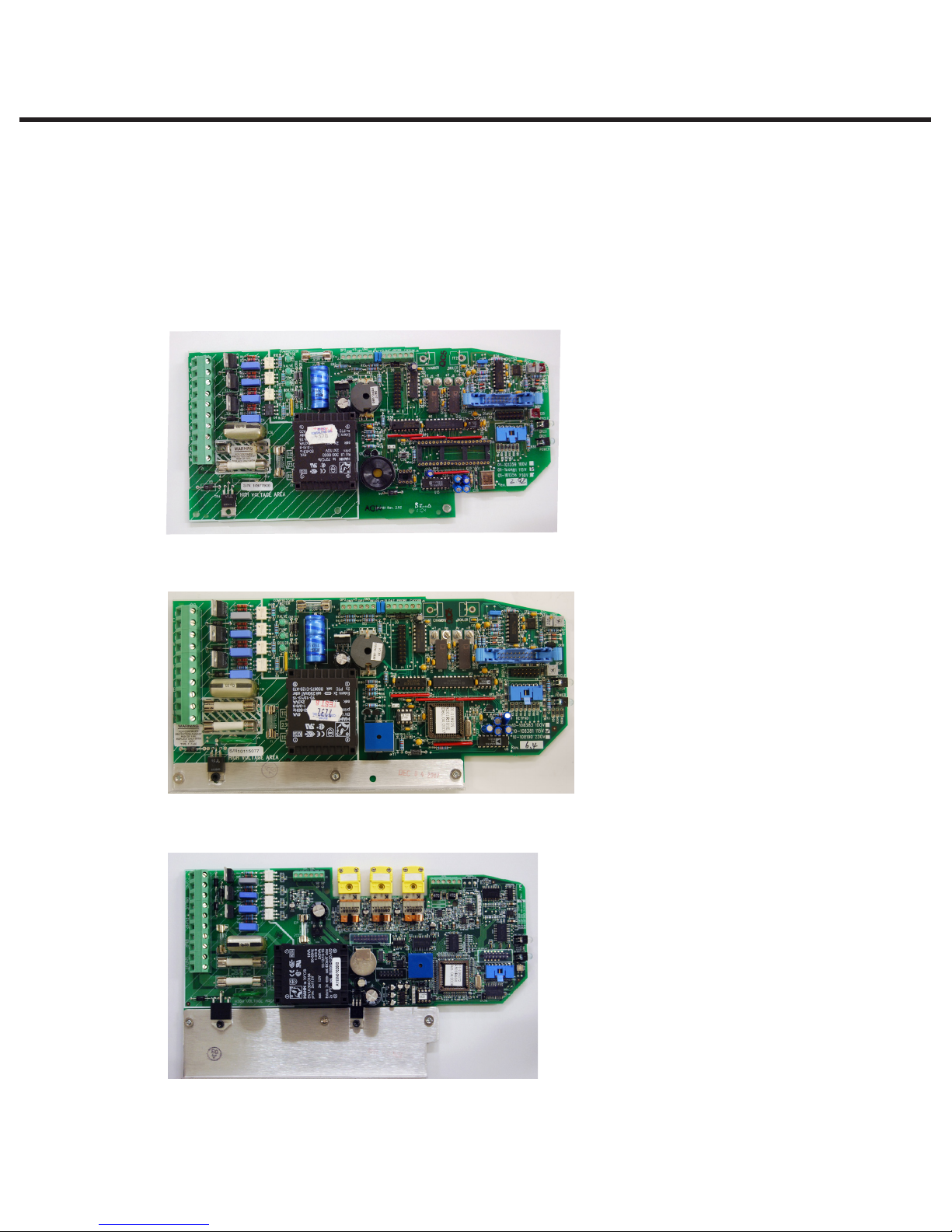
Identifying Controller Board Types
There are three different types of controller boards that may be encountered in STATIM 5000/
5000S/5000 G4 type units (See ‘PCB revision’ above). They can be identified as below (Figure 3):
Figure 3
Revision 2.x/5.x type board (1995 – 2004):
Typical features:
• Revision number bottom right hand
side.
• Rectangular microprocessor plus
EPROM
• ‘W1’ jumper for calibration
• Blue ‘pressure interface/printer’
connector
Revision 6.x type board (2004 - 2007):
Revision 7.x type board (2007 to present):
Typical features:
• Revision number bottom right hand
side.
• Square microprocessor plus EPROM
• ‘W1’ jumper for calibration
• Blue ‘pressure interface/printer’
connector
Typical features:
• Up to revision 7.30, the revision
number is on the top right hand side
(printed vertically)
• From revision 7.4 onwards, the
revision number is on the bottom left
hand side (printed horizontally) under
the connector J1
• Square microprocessor plus EPROM
• NO ‘W1’ jumper for calibration
• NO Blue ‘pressure interface/printer’
connector
• All components integrated on single
board
• Surface mount type component.
• ‘Push in’ yellow thermocouple
connectors.
STATIM 5000/5000S/5000 G4 Service Guide
STAT
IM
2000/2000S Service Guide
Page 9
1. Identifying STATIM 5000 Units
96-106775 Rev 5.0
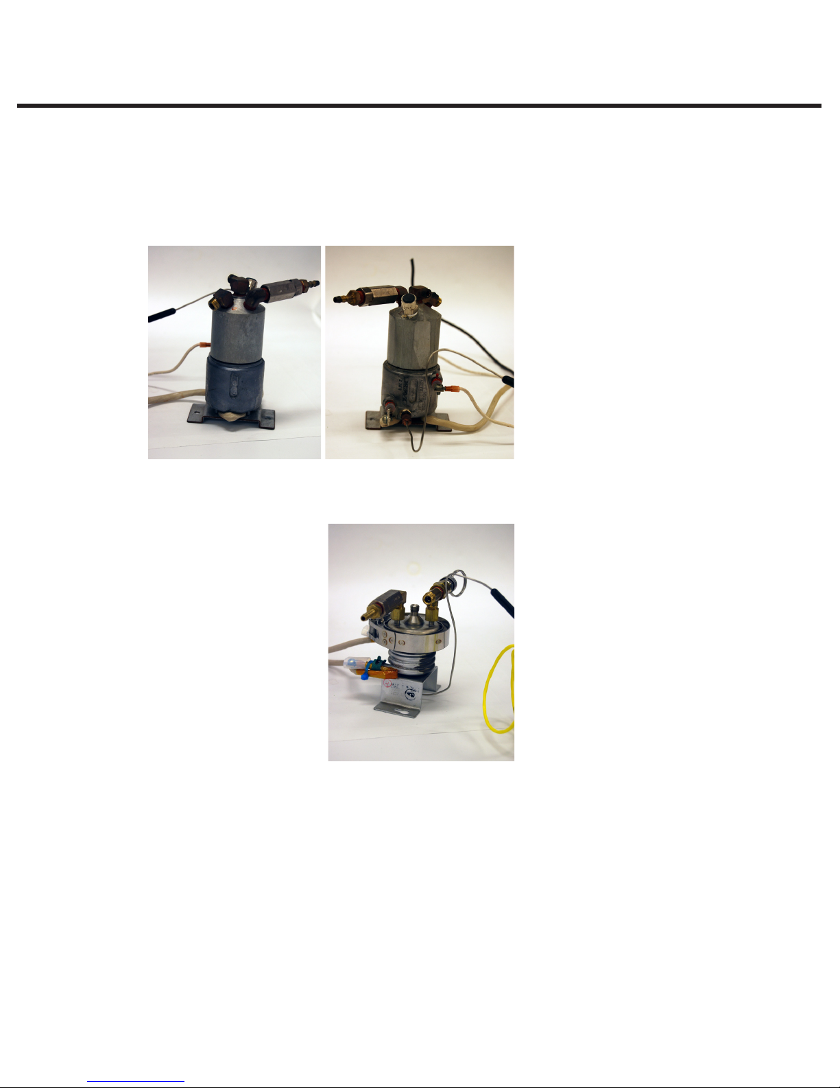
Identifying Steam Generator Types
There are three different types of steam generator (boiler) that may be encountered in STATIM
5000/5000S/5000 G4 units. They can be identified as below (Figure 2):
Aluminum steam generator with internal thermocouple (1995 – 2004):
Typical features:
• 70 p.s.i. pressure relief valve (PRV)
(no ring pull)
• Thermocouple embedded in side of
steam generator
• Software required to drive this steam
generator = R1xx/R2xx (revision
2.x/5.x PCB)
Stainless steel steam generator (2004 – 2005):
Typical features:
• Software required to drive this steam
generator = R4xx (revision 6 PCB only)
Page 10
STAT
STATIM 5000/5000S/5000 G4 Service Guide
IM
2000/2000S Service Guide
1. Identifying STATIM 5000 Units
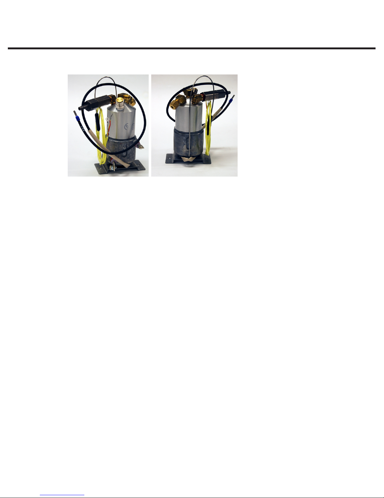
Aluminum steam generator with external thermocouple, a.k.a. ‘ALEX’ boiler (2005 – present):
Typical features:
• 43.5 p.s.i. pressure relief valve (PRV)
(ring pull on S models, no ring pull on
non S models)
• Thermocouple clamped to underside
of steam generator
• Blanking plug in the side of steam
generator in original thermocouple
position
• Software required to drive this steam
generator is R5xx for revision 6 PCB
and R6xx for revision 7 PCB
96-106775 Rev 5.0
STATIM 5000/5000S/5000 G4 Service Guide
STAT
IM
2000/2000S Service Guide
Page 11
96-106775 Rev 5.0
WARNINGS AND
PRECAUTIONS
If you have questions about the unit you are repairing, please do not hesitate to
contact your local SciCan representative for information. Also, the STATIM is heavy.
Exercise caution and seek assistance when lifting or carrying units.
EXERCISE CAUTION
• Hazardous voltages are accessible when the cover is removed.
• Disconnect the power cord before servicing the power mains portion of the
controller board and associated devices.
PERFORM TESTS
• If the cover is removed, a dielectric strength test (Hi-Pot) AND a protective
bonding impedance test (ground continuity) must be performed on the STATIM
when the work is completed and after the cover has been returned to the unit.
PROTECT THE UNIT
• Use only steam-process distilled water in the STATIM.
• The STATIM contains electronic circuitry that is static sensitive. Always wear a
static strap when working with or near printed wiring boards. In addition, use
static footstraps, grounding mats and grounded work surfaces when servicing
microprocessor devices. Transport boards and devices in static protected bags.
• Ensure there is sufficient steam-process distilled water in the STATIM before
activating the pump.
• In order to ensure adherence to the applicable safety agency approvals,
state, provincial, regional and national laws, replace components with SciCan
approved parts only.
Page 12
STAT
STATIM 5000/5000S/5000 G4 Service Guide
IM
2000/2000S Service Guide

2. Tools, Maintenance Schedules, Procedures and Testing
96-106775 Rev 5.0
Tools, Maintenance Schedules,
Procedures and Testing
Tools
STATIM specific items from SciCan
Before a STATIM can be serviced, the following special tools are required in addition to your
service tool kit. These tools are available from SciCan or your nearest service depot:
1. Control box SciCan Part # 01-103141S
2. Pump tester SciCan Part # 01-100713S
3. Water conductivity tester SciCan Part # 01-103139S
4. Solenoid plunger tube wrench SciCan Part # 01-103471S
5. 9/64” ball-end allen-key (hex) screwdriver SciCan Part # 01103469S
6. Calibration cassette,
SciCan 5000 Non S models only SciCan Part # 01-103087S
7. Calibration cassette,
SciCan 5000 All models SciCan Part # 01-106366S
Generic reference devices for calibration
8. Calibrated digital thermometer with ‘K’ type probe
9. Calibrated digital voltmeter with accuracy of 0.001 Volts
10. Calibrated digital pressure meter, 0 – 400 kPa absolute/0 – 7 bar absolute
More details on recommended devices can be found in section ‘Recommended Reference Meters’
Electrical safety test devices
11. Hi-Pot tester
12. Ground continuity tester
13. Static strap
14. Static bags
General tool list
• Phillips screwdriver
• Flat-blade electrician’s screwdriver
• Potentiometer trimmer
• Needle nose pliers
• Wire cutters
• Wrench 3/8” A/F
• Wrench 7/16” A/F
• Wrench 9/16” A/F
• Wrench 11/16” A/F
• Wrench 7/8” A/F
Note: This tool list is a guide and suggests what is the minimum required to remove and replace
components in the STATim. Other tools may be required as an aid to servicing at the discretion of
the individual service engineer.
STATIM 5000/5000S/5000 G4 Service Guide
STAT
IM
2000/2000S Service Guide
Page 13
2. Tools, Maintenance Schedules, Procedures and Testing
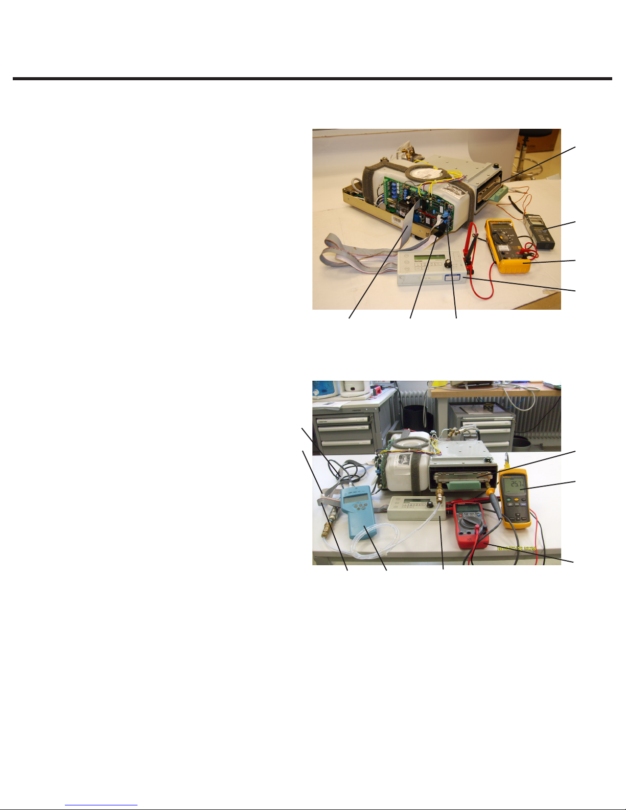
Sample equipment set up for calibration of a non-S unit
96-106775 Rev 5.0
1. Calibration cassette with detachable
thermocouple
2. Digital voltmeter
3. Digital thermometer
4. (no pressure meter required)
5. Control box
6. 2x7 ribbon cable, LCD connector
(connect to Controller Board header
P3)
7. 1x7 cable, keypad connector
(connect to Controller Board header
P4)
8. 2x10 molded socket, test connector
(connect to Controller Board header
P1)
8 7 6
Sample equipment set up for calibration of S unit
1. Calibration cassette.
2. Digital voltmeter
3. Digital reference thermometer
with thermocouple. (Fluke 51
with 80PK-26 probe shown)
4. Digital reference pressure meter
(S only) (Druck DPI 750 R shown)
5. Control box
6. LCD connector cable (connect
to Controller Board header P3)
7. Keypad connector cable (connect
to Controller Board header P4)
8. Test connector cable (connect to
Controller Board leader P1)
8
7
6
4 5
1
3
2
5
Figure 1
1
3
2
Figure 2
NOTE: The following section describes in greater detail the equipment depicted in Figures 1
and 2.
Page 14
STAT
STATIM 5000/5000S/5000 G4 Service Guide
IM
2000/2000S Service Guide
2. Tools, Maintenance Schedules, Procedures and Testing
96-106775 Rev 5.0
The Control Box
NOTE: Late model STAT
Rev.7 boards can be calibrated with the
cover on using the unit’s software and
keypad, making use of the Control Box
as an option. For older models, use of a
control box is required.
The Control Box (5) is a service tool
that allows a technician to operate the
unit while it is being serviced. There are
two kinds of Control Boxes you may
encounter: one uses toggle switches,
the other uses a membrane keypad
arrangement similar to the keypad on the
unit.
When connecting the Control Box connectors to the Controller Board note the positions of Pin
number 1 of the Control Box test connectors and Pin number 1 of the Controller Board headers.
The Control Box has a display (LCD) and a variety of control switches that allow the technician to:
IM
s with
Figure 3
1. Operate the unit independently of the keypad mechanism, to manually activate the pump,
valve or compressor, or run cycles.
2. Make frequently used Controller Board measurements by providing a common output and
rotary switch for signal selection during calibration. See the Calibration Instructions in chapters
4 and 5 of this service manual.
If only the display and button functions are being used, connect the LCD cable (6) to Controller
Board connector P3, the keypad cable (7) to Controller Board connector P4 and power the
STAT
IM
ON.
If the override or measurement functions are being used, connect the test connector cable (8) to
connector P1 of the Controller Board in addition to the other cables.
When using a toggle switch model of the Control Box, turn the switch to the ON position to
activate the desired device. To turn the device OFF, turn the switch to the AUTO position. To
select, start and / or stop a cycle, activate the appropriate push-button switch on top of the
Control Box.
Calibration uses the Select out +, Select out - jacks and a setting on the Rotary Switch to set the
calibration operation desired for Revision 3.x/4.x Controller Boards (for STATim 2000 units only).
See Calibration Procedure 1 or chapter 4 of this service manual.
When using a keypad model of the Control Box, the keypad switch must be held down to turn the
desired device ON. Vref measurements use test leads, the Vref + and Vref - jacks and a voltmeter
hooked up in series. Calibration uses the Select out + and Select out - jacks, test leads and a
setting on the Rotary Switch to set the calibration operation desired for Rev. 3.x/4.x Controller
Boards (for STATim 2000 units only). The keypad of this Control Box provides the same features
as a STATIM keypad. Note: The Control Box is for use with STATIM products ONLY.
STATIM 5000/5000S/5000 G4 Service Guide
STAT
IM
2000/2000S Service Guide
Page 15
2. Tools, Maintenance Schedules, Procedures and Testing
96-106775 Rev 5.0
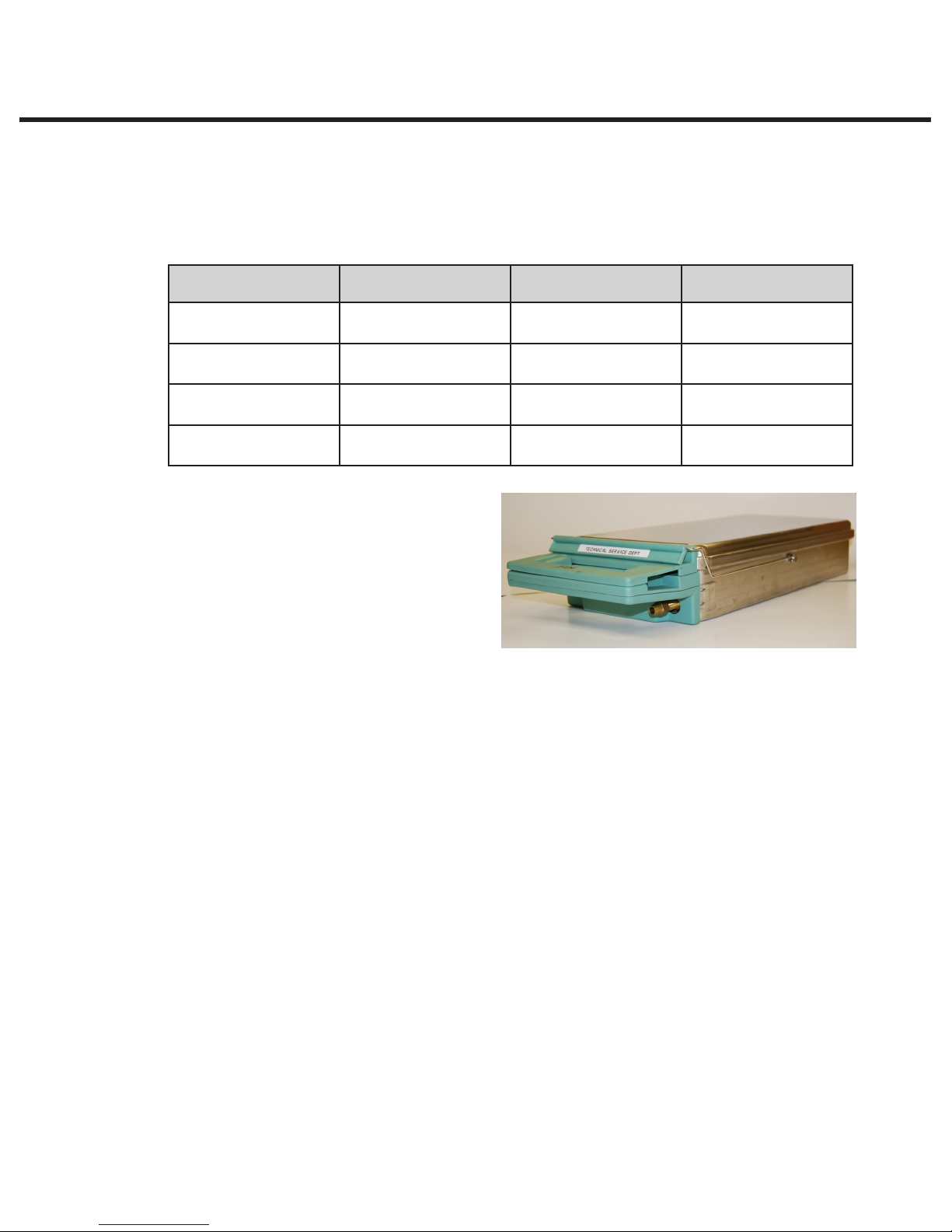
Calibration Cassettes and Reference Meters
Specially designed calibration cassettes allow technicians to take readings from within the
cassette while the unit is in operation. In addition, calibration also requires the use of certain
reference meters. Use the table below to identify the meters you will require.
Sterilizer type Part Number Description Meter types required
IM
2000 (non S)/
STAT
2000 G4
STATIM 5000 (non S)/
5000 G4
IM
STAT
STATIM 5000S/
2000S/
2000S G4
5000S G4
01-103087S Calibration cassette
IM
2000
STAT
01-103088S Calibration cassette
IM
5000
STAT
01-103088S Calibration Cassette
2000S B
01-106367S Calibration Cassette
5000S C
Temperature only
Temperature only
Temperature and
pressure
Temperature and
pressure
Calibration Cassettes
The cassette of the STATim unit is effectively
a fixed volume chamber that contains
instruments during sterilization. Saturated
steam at a specific temperature and pressure
is introduced to produce the correct
conditions for sterilization. The cassette is
part of a sealed system designed to contain
the pressurized steam. To calibrate the unit’s
temperature and pressure (if appropriate) monitoring devices, a special calibration cassette must
be used. The calibration cassette allows a technician to independently monitor the temperature
and pressure inside the cassette, ensuring the unit is operating in accordance to its original
specifications and to national/international standards.
Figure 4
The relevant cassette types are detailed in the chart above, and the following important
information should be noted before choosing the appropriate cassette to use.
• Non S unit cassettes require a 1.6mm (1/16”) temperature probe and cannot be used with
a 3.2mm (1/8”) temperature probe. (See meter details for probe diameter).
• S unit cassettes have temperature fittings (one fitted and one in the cassette accessories
supplied) that will allow the use of both 1.6mm (1/16”) and 3.2mm (1/8”) temperature
probe. (See meter details for probe diameter).
• S unit cassettes are designed for both temperature and pressure reference meters and are
suitable for all models, S and Non S. If these cassettes are acquired, the non S, single port
cassette is not required.
• The non S unit cassettes should not be used to calibrate S class units.
• Please note that when calibrating non-S units with an S unit cassette that the pressure
meter will not be required and the test port will require the pressure tube supplied with the
cassette to be connected to the pressure fitting to prevent steam leakage.
Page 16
STAT
STATIM 5000/5000S/5000 G4 Service Guide
IM
2000/2000S Service Guide

2. Tools, Maintenance Schedules, Procedures and Testing
96-106775 Rev 5.0
Reference Meters
Calibration reference meters are important for accurately setting the STATIM unit so that the
correct sterilization conditions (temperature and pressure) occur in accordance with the original
specifications of the unit and national/international standards.
When ordering any digital thermometer and temperature probe, ensure that the supplier is aware
that the area where the most accuracy is required is between 130°C and 140°C.
Temperature meters and probes should always be calibrated as a matched pair.
Test equipment should be calibrated on a regular basis based on the manufacturer’s
recommended calibration interval.
Calibration of reference equipment used with autoclaves should ALWAYS be to national or
international standards by a certified calibration laboratory.
A number of meters are recommended by SciCan and are referenced as follows:
For non-S unit calibration
The following reference meters are recommended for use with 01-103087S and 01-103088S test
cassettes:
• Omega HH81A single channel multifunction digital thermometer (www.omega.com)
• Omega TJ36-CASS-116G-6-SMP-M Temperature Probe (with SMP-M miniature male
connector).
Note: the above probe is 1.6mm (1/16”) diameter.
For S unit calibration
The following options are recommended for use with 01-106366S and 01-106367S test cassettes:
• A set of two independent meters, one pressure and one temperature.
• An integrated hand-held pressure and temperature calibrator.
Note: The thermocouple entry fitting on the S class cassette will need to be changed from the
3.2mm (1/8”) diameter fitting to the 1.6mm (1/16”) diameter fitting if using the Omega meter.
The two independent meters have been included where the user may already have an Omega
meter for non-S use who is upgrading to S class use, when only a pressure meter will be required.
They are also the lower cost options over the integrated device.
STATIM 5000/5000S/5000 G4 Service Guide
STAT
IM
2000/2000S Service Guide
Page 17
2. Tools, Maintenance Schedules, Procedures and Testing
96-106775 Rev 5.0
Recommended separate temperature and pressure meters for S unit calibration
temperature
• Fluke 51 Series II Digital Thermometer.
• Fluke 80PK-26 SureGrip Tapered Temperature Probe.
Notes:
• The flexible thermocouple included with the Fluke digital thermometer will not be used for
calibrating SciCan sterilizers. If you wish to use the flexible thermocouple in the future,
SciCan advises you to consult the digital thermometer’s manual for setting a temporary
offset, if required.
• The above probe is 3.2mm (1/8”) diameter.
• Technicians already in possession of the Omega HH81A or equivalent, and the associated
probe can use this meter as a replacement for the Fluke 51 and 80PK-26 probe. Note that
the probes are of different diameter and a cassette compression fitting change may be
appropriate.
Pressure
• Druck DPI 705R Absolute Pressure Meter with external 0 - 7 bar absolute pressure
transducer with ¼” NPT female thread.
Page 18
STAT
Figure 5
STATIM 5000/5000S/5000 G4 Service Guide
IM
2000/2000S Service Guide
2. Tools, Maintenance Schedules, Procedures and Testing
96-106775 Rev 5.0
Combined Temperature and Pressure Meter
• Heise PTE-1 Handheld LCD digital calibrator complete with temperature and pressure
modules, and PT100 probe as follows:
Meter (without data logging capabilities) — PTEC = X X 4 4A
Pressure Module — HQS2 B A A 400 kPa A
Temperature Module — HQS RT1 PT-100
RTD Probe Pt-100 — PT5
Notes:
• These product references are very specific, and the local supplier of Heise equipment
(see www.heise.com) should be consulted prior to confirming order codes.
• The meter above is of the non data logging variety. If data logging is required, please
consult order code variations from Heise data sheet.
• The above probe is 3.2mm (1/8in) diameter.
STATIM 5000/5000S/5000 G4 Service Guide
STAT
IM
2000/2000S Service Guide
Figure 6
Page 19

2. Tools, Maintenance Schedules, Procedures and Testing
96-106775 Rev 5.0
Setting Up your Reference Meters
With certain meter types, some sub-assembly procedures will need to be undertaken to connect
the device to your Statim calibration cassette. All cassettes are supplied with the necessary
accessories to enable you to convert your meter of choice from those recommended above, to the
appropriate fitting on the cassette.
01-103087S and 01-103088S cassettes (non S calibration) with Omega HH81A reference
meter and TJ36-CASS-116G-6-SMP-M Temperature Probe.
No sub-assembly required.
To insert the temperature probe (thermocouple) into the compression fittings, loosen the clamp
nut attached to the cassette extension fitting and insert the probe into the fitting as far as it will go.
A slight resistance will be felt as the probe passes through the seal. Tighten the clamp nut until a
steam/air tight seal is achieved. DO NOT OVERTIGHTEN.
NOTE: The non S calibration cassette fitting is NOT compatible with the Fluke and Heise 1/8”
(3.175mm) temperature probes.
01-106366S and 01-106367S cassettes (S-class calibration) with ALL recommended
reference meters
S-class calibration cassette kits contain a number of accessories for use with various
recommended reference meters and will need to be set up to suit the appropriate meters before
use.
Contents of calibration cassette kit:
•Cassette(2000Sor5000Sasappropriate)with‘generic’pressureandtemperaturettings
attached (see Figure 7 below)
•Accessoriesasfollows:(insidethecassette)
1 x Pressure tube
2 x Male Swagelok B-QC4-S-2PM ‘Quick Connect’ fittings.
1 x 1/8 NPT female to ¼ NPT male adaptor
1 x 1/8” (3.175mm) probe fitting.
Page 20
STAT
STATIM 5000/5000S/5000 G4 Service Guide
IM
2000/2000S Service Guide
2. Tools, Maintenance Schedules, Procedures and Testing
96-106775 Rev 5.0
Figure 7. S-class ‘generic’ fitting configuration (2000S cassette shown)
Setting up the temperature fittings for use with the recommended temperature
reference meter(s)
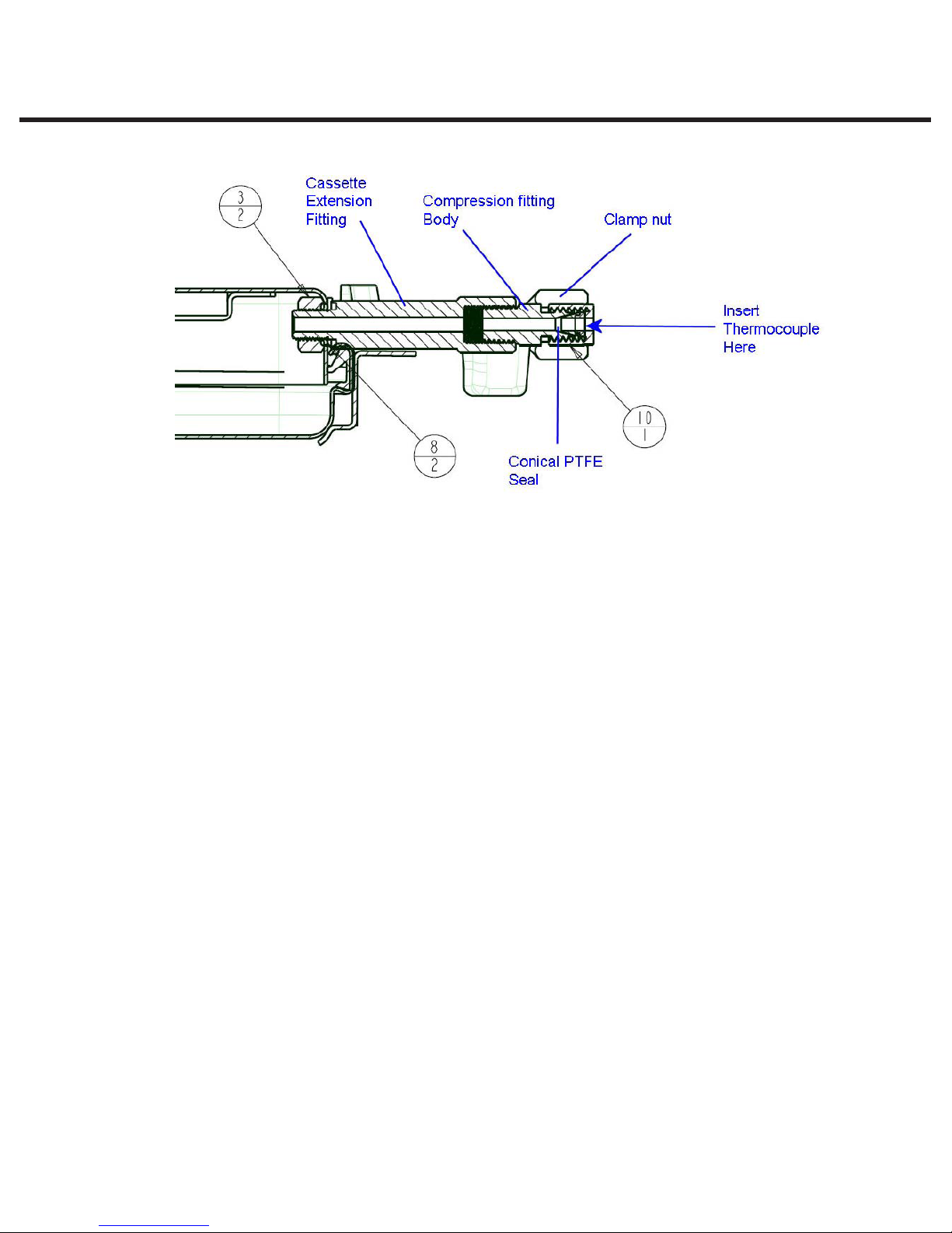
The temperature fitting (right hand fitting when facing the front of the cassette) is fitted with a
compression fitting that consists of a body, clamp nut and conical compression washer. (See
Figure 8)
There are two fittings supplied with the cassette, one for a 1/8” (3.175mm) temperature probe and
one for a 1/16” (1.6mm) temperature probe.
NOTE: The 1/16” fitting is attached to the cassette when supplied and the 1/8” fitting is in the pack
of accessories supplied with the cassette.
STATIM 5000/5000S/5000 G4 Service Guide
STAT
IM
2000/2000S Service Guide
Page 21
2. Tools, Maintenance Schedules, Procedures and Testing
96-106775 Rev 5.0
Figure 8. Temperature fitting cut-away
If you have the SciCan supplied Omega HH81A type temperature reference meter with the 1/16”
(1.6mm) temperature probe (normally used with the Non S-class type calibration cassette) then
the compression fitting attached to the S class cassette is correct and does NOT have to be
removed.
If you have either the Fluke 51 type temperature reference meter, or Heise PTE1 type combined
temperature and pressure reference meter then the 1/16” (1.6mm) compression fitting (complete)
will need to be removed from the extension piece attached to the cassette and replaced with the
1/8” (3.175mm) compression fitting from the accessory kit, as both of these meters have 1/8”
(3.175mm) thermocouple probes.
NOTE: PTFE tape should be used when assembling these parts to ensure a steam tight seal.
To insert the relevant temperature probe (thermocouple) into either of the appropriate compression
fittings, loosen the clamp nut and insert the probe into the fitting as far as it will go. A slight
resistance will be felt as the probe passes through the conical seal. Tighten the clamp nut until a
steam/air tight seal is achieved. DO NOT OVERTIGHTEN.
Page 22
STAT
STATIM 5000/5000S/5000 G4 Service Guide
IM
2000/2000S Service Guide
2. Tools, Maintenance Schedules, Procedures and Testing
96-106775 Rev 5.0
Setting up the pressure fittings for use with the recommended pressure
reference meter(s)
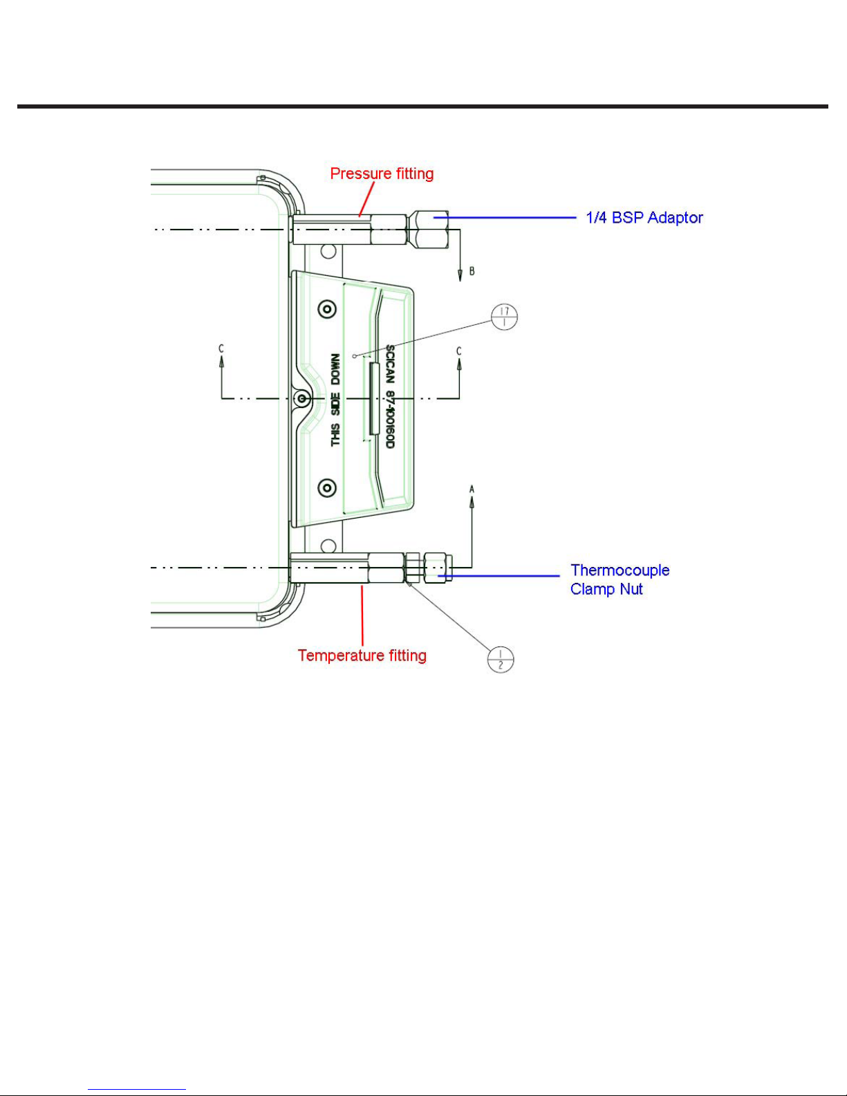
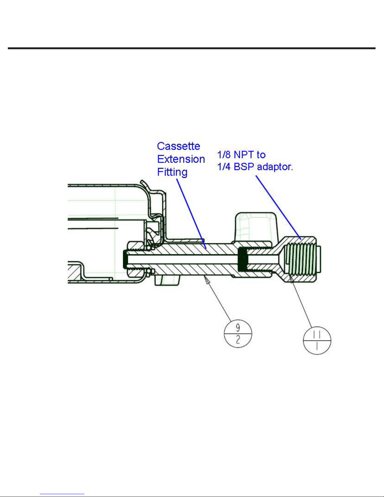
NOTE: The pressure fitting (left hand fitting when facing the front of the cassette) is fitted with an
adaptor to attach ¼” BSP devices such as hypodermic pressure fittings. (See Figure 9 below).
This adaptor is not used with the standard SciCan pressure tube and should be removed from the
cassette extension fitting before attaching the pressure tube.
Figure 9. Pressure fitting cut-away
To set up the cassette for use with the recommended Druck DPI705R and Heise PTE1 pressure
reference meters, proceed as follows:
Remove the 1/8 NPT to ¼ BSP adaptor. (The accessories for the cassette include 2 male
Swagelok ‘Quick connect’ fittings (see Figure 10).
STATIM 5000/5000S/5000 G4 Service Guide
STAT
IM
2000/2000S Service Guide
Page 23
2. Tools, Maintenance Schedules, Procedures and Testing
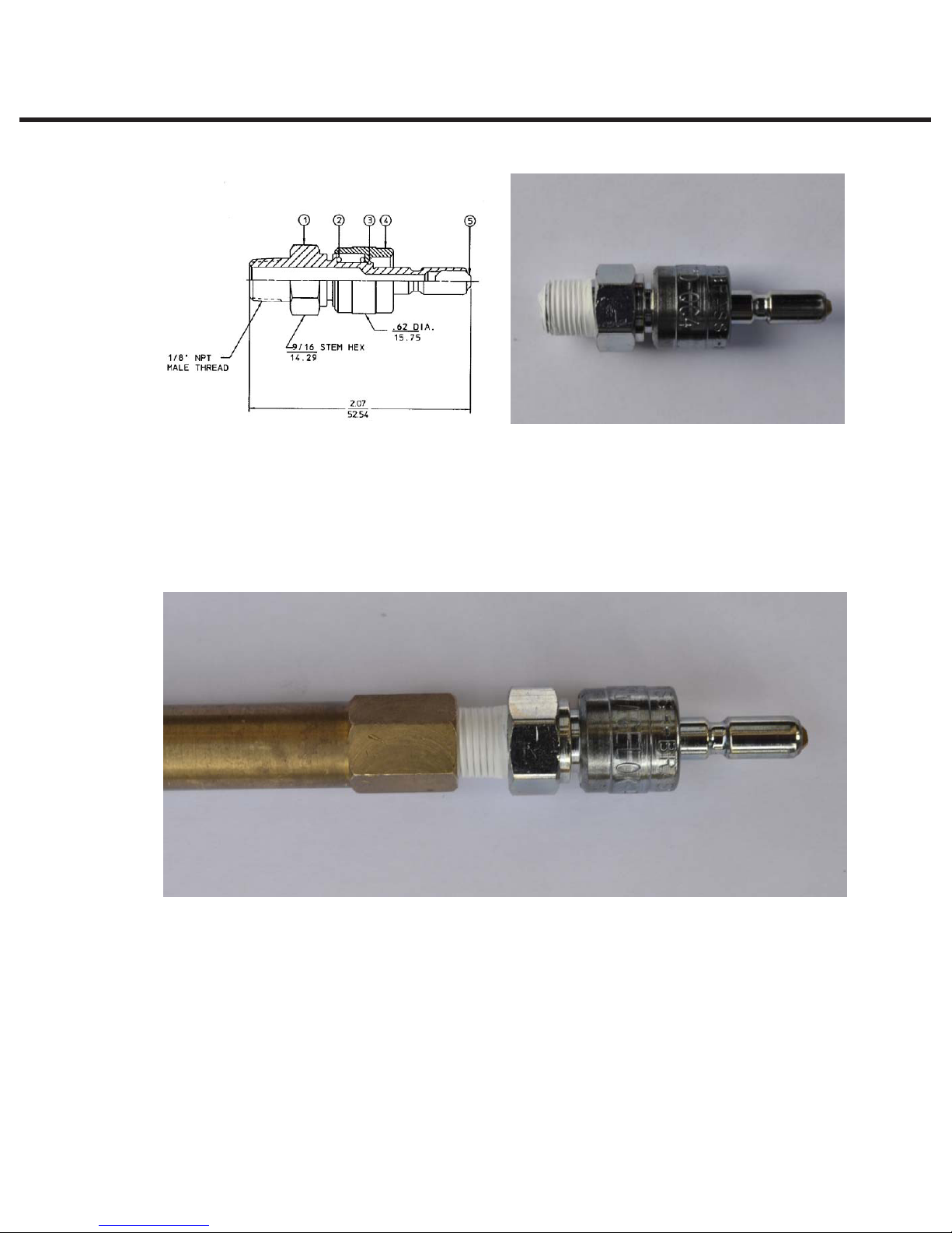
Figure 10. Male Swagelok B-QC4-S-2PM ‘Quick Connect’ fitting.
Attach and tighten the ‘Quick Connect’ fitting to the cassette extension fitting in place of the 1/8
NPT to ¼ BSP adaptor (see Figure 11).
96-106775 Rev 5.0
NOTE: PTFE tape should be used when assembling these parts to ensure a steam tight seal.
Figure 11. Male Swagelok ‘Quick Connect’ fitting and cassette extension fitting assembly.
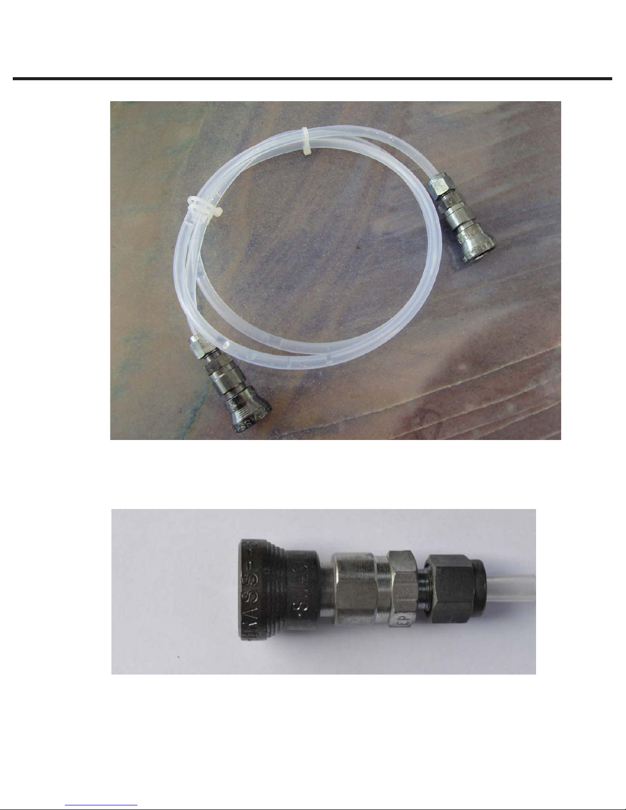
Attaching the pressure tube to the cassette
The pressure tube (see Figure 12) supplied with the calibration cassette is designed to insulate
the pressure transducer used with the pressure reference meter from the high temperatures
experienced during sterilization, which may damage the transducer.
Page 24
STAT
STATIM 5000/5000S/5000 G4 Service Guide
IM
2000/2000S Service Guide
2. Tools, Maintenance Schedules, Procedures and Testing
96-106775 Rev 5.0
Figure 12
The tube is fitted with a Swagelock, self sealing ‘Quick Connect’ QC4 female connector (see
Figure 13) on either end. These connectors attach to the male ‘Quick Connect’ fitting shown in
Figure 10 above.
Figure 13. Swagelock ‘Quick Connect’ QC4 female connector
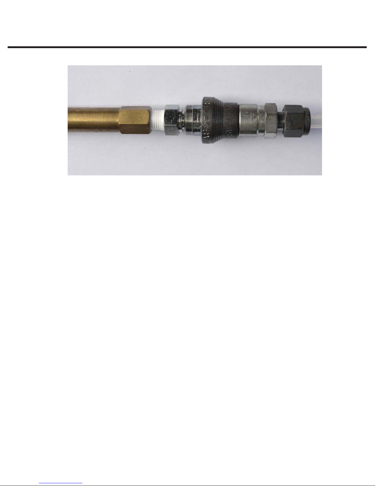
To attach the pressure tube to the cassette (via the male Swagelok connector), press the male and
female fitting together until a ‘click’ is heard and the couplings are firmly attached. (See Figure 14)
STATIM 5000/5000S/5000 G4 Service Guide
STAT
IM
2000/2000S Service Guide
Page 25
2. Tools, Maintenance Schedules, Procedures and Testing
Figure 14. Assembled male fitting, female fitting and cassette extension fitting
96-106775 Rev 5.0
Attaching the pressure tube to the recommended pressure reference meter (s)
Important notes:
•AttachingthepressuretubetothereferencemeterisachievedusingthesecondmaleSwagelok
b-qc4-s-2pm fitting supplied with the cassette.
•Attachingthetubetotheconnectorisasdescribedinthesectionabove,however,thesecond
male fitting will need to be installed onto the pressure reference meter prior to attempting this.
•Howthesecondmalettingisattachedwilldependonthetypeofreferencemeterused.
Assembling the Swagelok b-qc4-s-2pm ‘quick connect’ fitting to the Druck dpi
705r absolute pressure meter external 0 - 7 bar absolute pressure transducer
with ¼” NPT female thread.
NOTE: To complete this assembly you will need to locate the 1/8 NPT female to ¼ NPT male
adapter supplied with the S-class calibration cassette. (See Figure 15 for assembly) .
Page 26
STAT
STATIM 5000/5000S/5000 G4 Service Guide
IM
2000/2000S Service Guide
2. Tools, Maintenance Schedules, Procedures and Testing
96-106775 Rev 5.0
Figure 15. Pressure transducer with adapter and Swagelok connector attached.
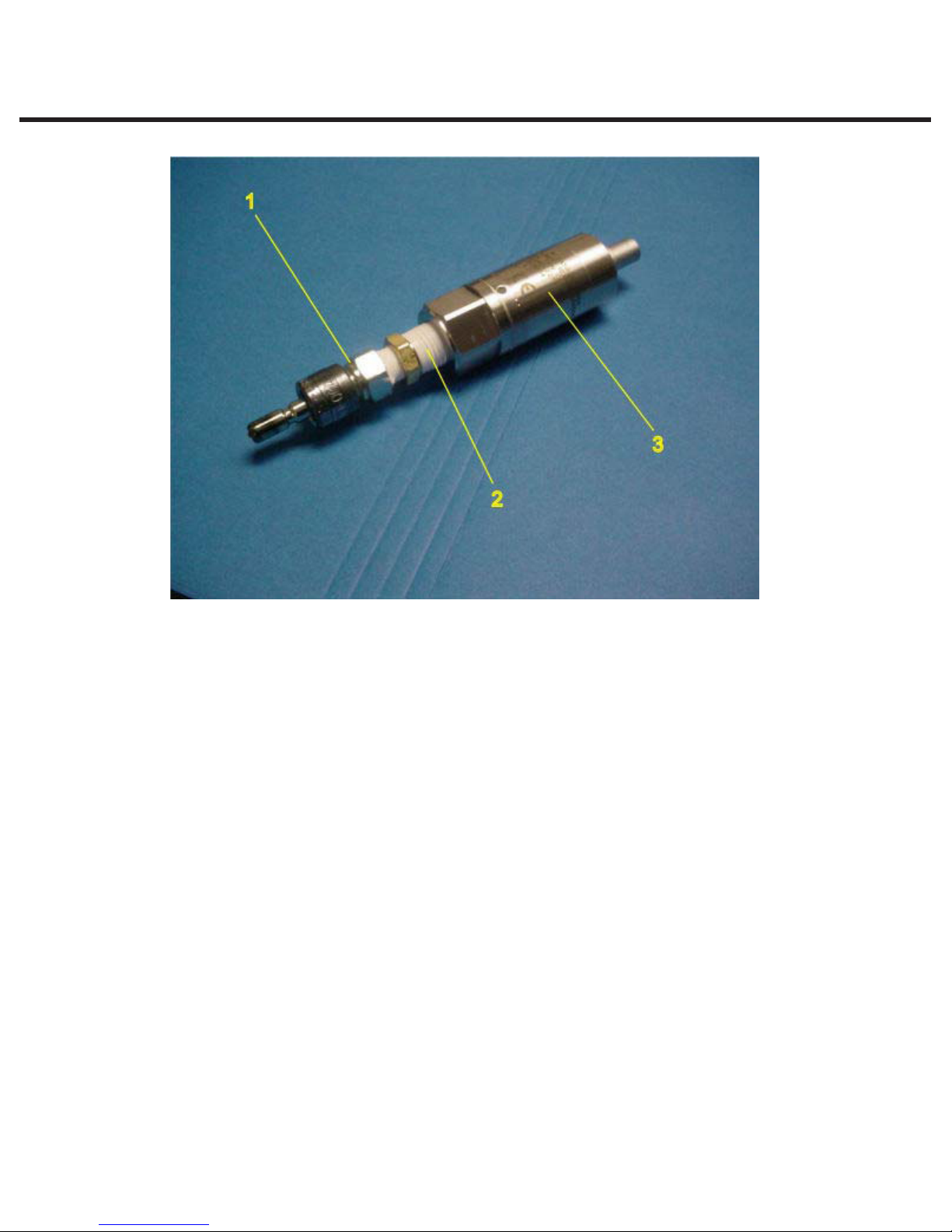
Install Swagelok connector (1) onto adaptor fitting (2) DO NOT OVERTIGHTEN FITTING.
NOTE: The use of P.T.F.E. tape as shown is essential to ensure the connection is free from steam
leaks. If the joint leaks, steam can enter the transducer and damage the unit internally.
Install assembly (from previous step) onto external pressure sensor (3) supplied with the Druck DPI
705R. DO NOT OVERTIGHTEN FITTING.
NOTE: The use of P.T.F.E. tape as shown is essential to ensure the connection is free from steam
leaks. If the joint leaks, steam can enter the transducer and damage the unit internally.
The pressure tube can now be attached to the pressure transducer.
STATIM 5000/5000S/5000 G4 Service Guide
STAT
IM
2000/2000S Service Guide
Page 27
2. Tools, Maintenance Schedules, Procedures and Testing
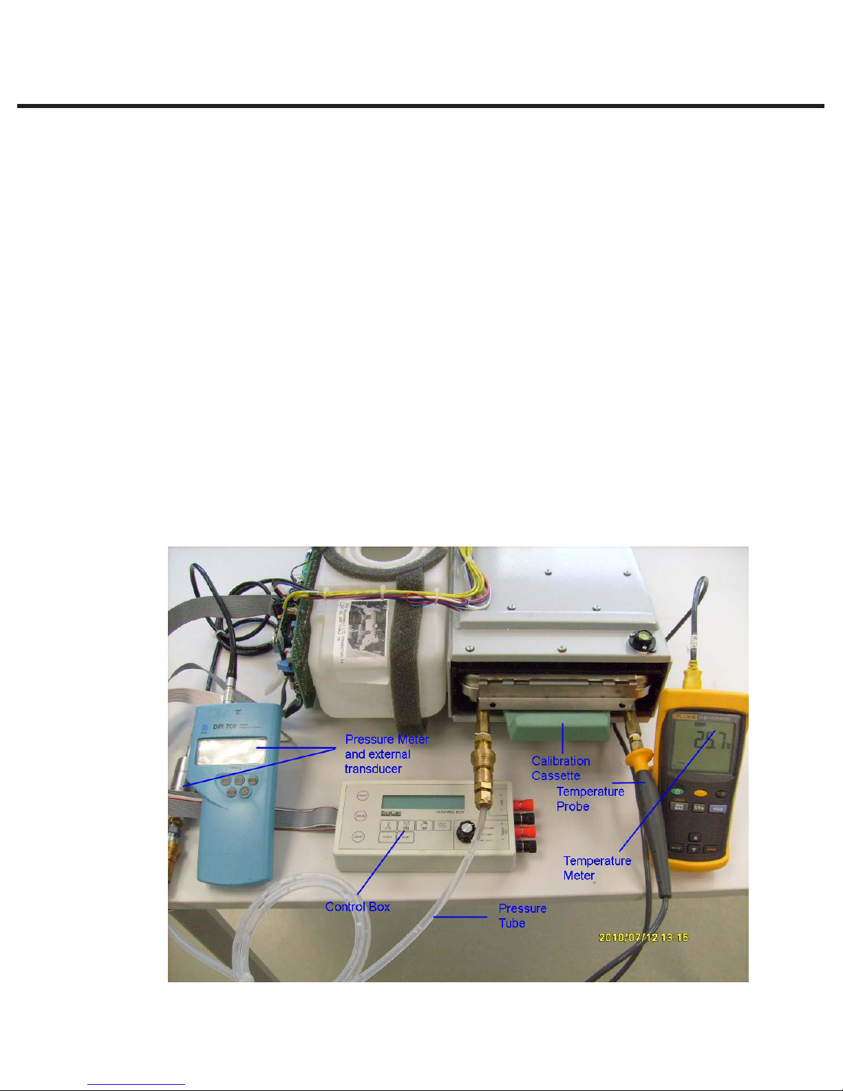
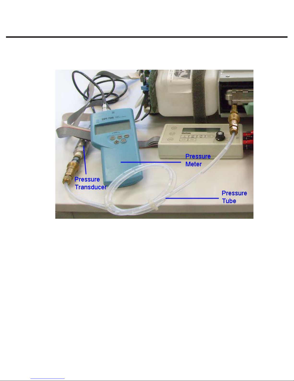
Figure 16, below, shows the meter, pressure transducer and pressure tube attached to a
calibration cassette.
96-106775 Rev 5.0
Figure 16
Page 28
STAT
STATIM 5000/5000S/5000 G4 Service Guide
IM
2000/2000S Service Guide
2. Tools, Maintenance Schedules, Procedures and Testing
96-106775 Rev 5.0
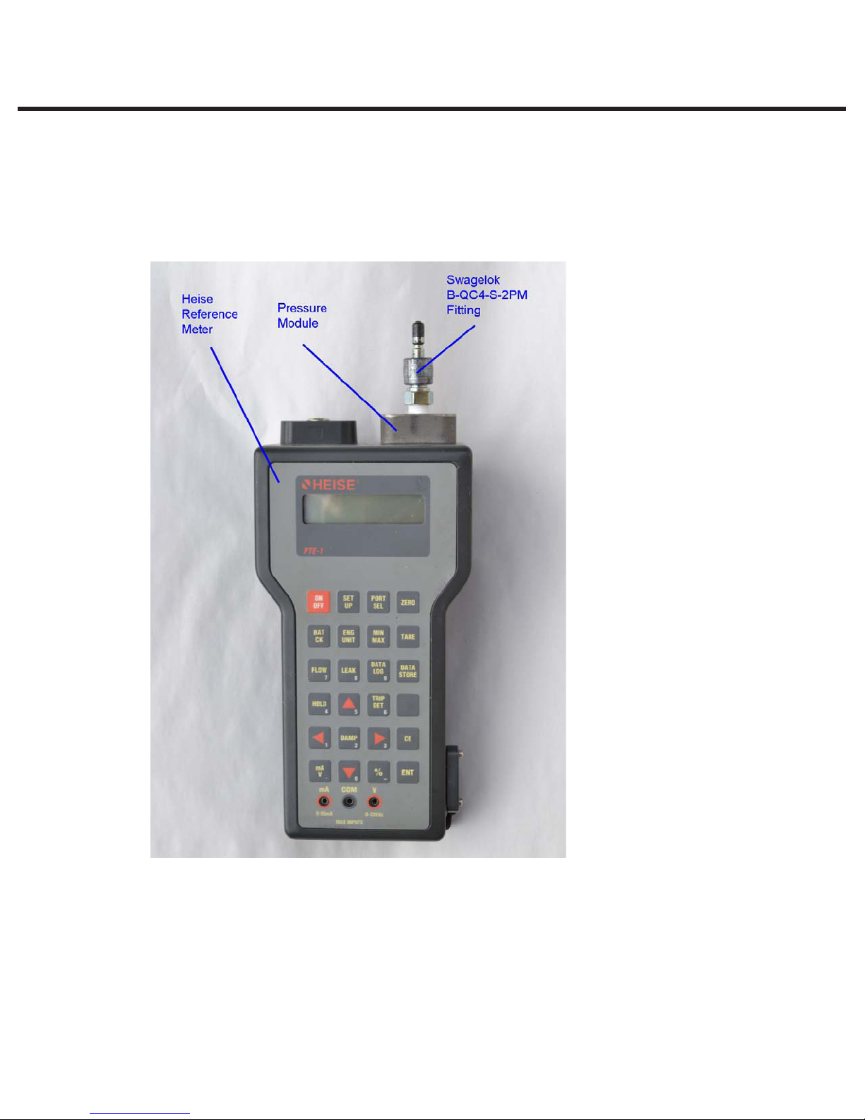
Assembling the Swagelok B-QC4-S-2PM ‘Quick Connect’ fitting to the internal
pressure module supplied with the Heise hand held calibrator.
NOTE: You do NOT need the 1/8 NPT female to ¼ NPT male adaptor for this device. (see Figure
17 for assembly).
Figure 17. Heise meter with
Swagelok fitting attached to
pressure module.
Insert and tighten the Swagelok fitting into the 1/8 NPT female thread of the pressure module. DO
NOT OVERTIGHTEN FITTING. NOTE: The use of P.T.F.E. tape as shown is essential to ensure
the connection is free from steam leaks. If the joint leaks, steam can enter the module and damage
the unit internally.
The pressure tube can now be attached to the pressure module.
STATIM 5000/5000S/5000 G4 Service Guide
STAT
IM
2000/2000S Service Guide
Page 29
2. Tools, Maintenance Schedules, Procedures and Testing
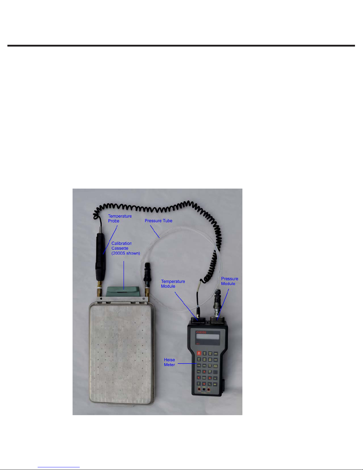
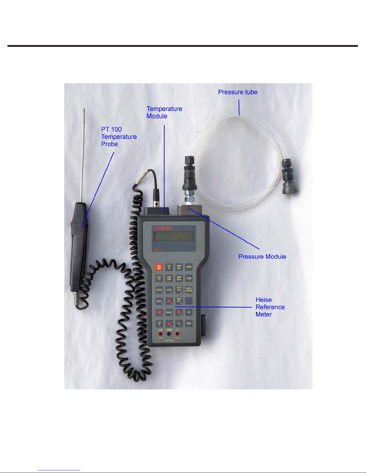
Figure 18, below, shows the meter with temperature probe and pressure tube ready to attach to a
calibration cassette.
96-106775 Rev 5.0
Figure 18. Heise hand held calibrator with temperature module, pressure module, PT 100
temperature probe and pressure tube.
Page 30
STAT
STATIM 5000/5000S/5000 G4 Service Guide
IM
2000/2000S Service Guide
 Loading...