

Page 1
STATCLAVE™G4 - Chamber Autoclave
Operator’s Manual
95-115362 CA EN R3
Page 2

Manufacturer’s Information and Customer Service Information
For all ser vice and repair inquiries:
Canada: 1-800-870-7777
techservice.ca@scican.com
Manufactured by:
SciCan Ltd.
1440 Don Mills Road,
Toronto, ON M3B 3P9
Canada
Telephone: (416) 445-1600
Fax: (416) 445-2727
Toll fre e: 1- 800-667-7733
STATCLAVE G4 Operator’s Manual, Copyright 2019 SciCan Ltd. All rights reserved.
Page 3
Quick Start Guide
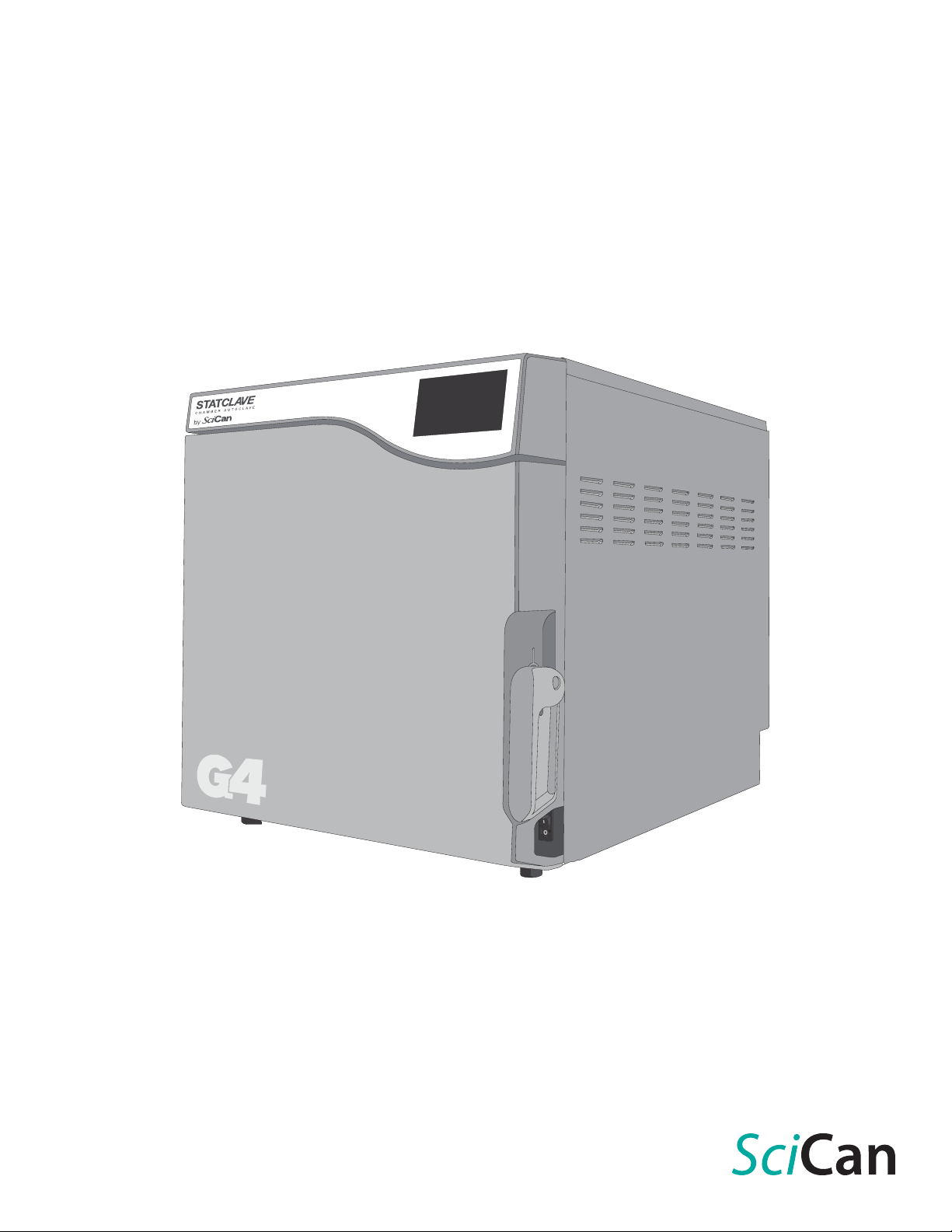
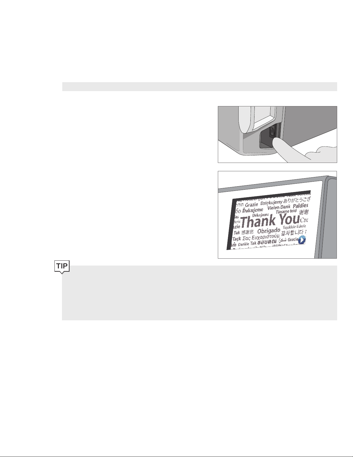
1. Switch the autoclave ON.
3. Ensure BOTH drainage tubes are connected at the back.
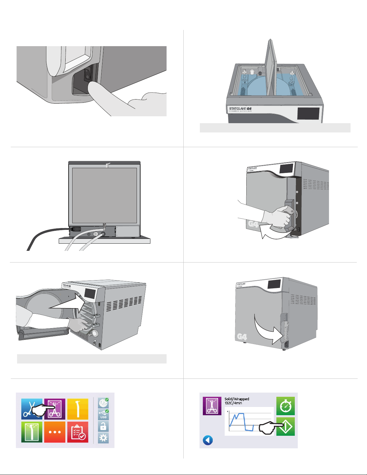
2. Ensure BOTH reservoirs are filled with high quality distilled water.
IMPORTANT! Never Use Tap Water.
More informati on IN SECTION 4.
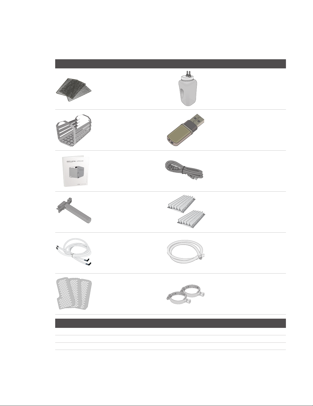
4. Pull up on the door latch to open the door.
More informati on in SECTION 2.3
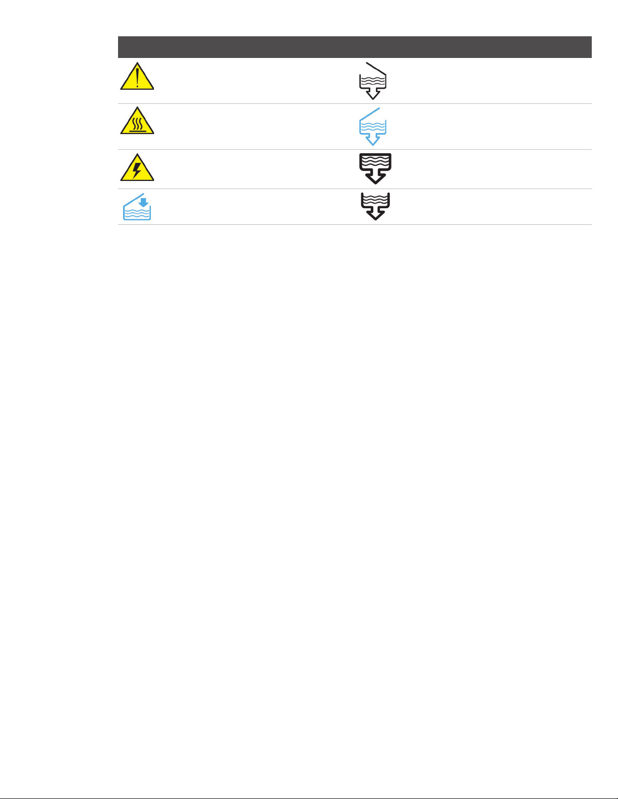
5. Insert the load.
CAUTION! Hot Chamber.
More informati on in SECTION 5.
7. Select a cycle.
More informati on in SECTION 1.7
6. Close and latch the door.
8. Press the START icon.
More informati on in SECTION 7.
Page 4

1. Your STATCLAVE 3
1.1 Checking the Package Contents 3
1.2 Important Information About Using Your STATCLAVE 4
1.3 Operating Principles, Key Features and Safety
Devices 5
1.4 Unit Overview 7
1.5 Touchscreen Overview 8
1.6 Using the Operation Screens 8
1.7 Unlocking the Door 9
9. Storing, Retrieving and Printing
Sterilization Records 45
9.1 Retrieving Cycle Information Using the Touchscreen 45
9.2 Retrieving Cycle Information Using the Web Portal 45
9.3 Retrieving Cycle Information Using
the USB Data Back Up 46
9.4 Connecting to a Printer 47
9.5 Adjusting your Print Settings 47
9.6 External Printer Specifications 47
2. Set Up 10
2.1 Installing Your STATCLAVE 10
2.2 Connecting and Powering Your STATCLAVE 11
2.3 Connecting Your STATCLAVE’s Water
Draining System 11
2.4 Connecting your STATCLAVE to a Network 13
3. Getting Started 15
4. Filling the Water Reservoirs 17
4.1 Manual Filling Using Reservoir Top 18
4.2 Manual Filling Using Quick Connector at Unit Front 19
4.3 Automatic Filling Using a VistaPure Specialized
Water Filtration System with Accumulation Tank 20
4.4 Automatic Filling Using External Water Tank
and Auxiliary Pump 21
5. Loading Instruments 22
5.1 Using the Chamber Rack 23
5.2 Wrapped Instruments 24
5.3 Unwrapped Instruments 26
5.4 Rubber and Plastic 27
5.5 Textiles and Surgical Packs 27
5.6 Using Biological and Chemical Indicators 27
6. Using Your STATCLAVE 28
6.1 Running a Cycle 28
6.2 Stopping a Cycle 30
6.3 Using the Delayed Start 31
6.4 Emergency Door Opening 32
6.5 Running a Bowie-Dick Test 33
6.6 Running a Vacuum Test 35
6.7 Using the Custom Cycle 35
10. Maintenance Procedures 48
10.1 Preventative Maintenance Message 48
10.2 Preventative Maintenance Schedule 48
10.3 Cleaning the Door Seal and Door Plate 49
10.4 Cleaning and Disinfecting the External Surfaces 49
10.5 Cleaning the Sterilization Chamber, Rack and Trays 49
10.6 Draining the Reservoirs for Cleaning 50
10.7 Cleaning the Water Reservoirs and Reservoir Filters 51
10.8 Cleaning the External Water Reservoir Tank 52
10.9 Cleaning the Chamber Filters 52
10.10 Replacing the Bacteriological Filter 53
10.11 Replacing the Door Seal 53
10.12 Using On-Screen Instructions 53
10.13 Enabling Remote Access for a Technician 54
10.14 Preparing the Unit for Shipping 54
11. Troubleshooting 55
12. Ordering Spare Parts and Accessories 58
13. Limited Warranty 59
14. Specifications 60
APPENDIX A – Software Icons 61
APPENDIX B – Software Screens 62
APPENDIX C – STATCLAVE Cybersecurity Statement 64
7. Sterilization Cycles 37
8. Using and Changing Settings 38
8.1 Setting Up Load Traceability with User ID, PIN,
and Process Enforced Function 40
8.2 Setting Drying Time 42
8.3 Setting the Stand-By Mode 42
8.4 Setting Up and Using Your STATCLAVE Web Portal 43
8.5 Registering for STATCLAVE Online Access 44
Page 5
1. Your STATCLAVE
1.1 Checking the Package Contents
When you receive your STATCLAVE, the items listed below will be included. If any of the items are missing, contact your dealer
immediately.
Included with your STATCLAVE
1 Chamber rack 1 USB Memory stick
1 Operator’s manual 1 Power cord
4 Stainless steel wire
instrument trays
1 Tray extractor with door
unlocking pin (in handle)
1 Waste bottle
2 Pouched instrument racks
The following terms appear in this manual:
CAUTION! A potential hazard to the operator or end patient
IMPORTANT! A situation that may affect the functioning of the unit.
TIP Additional information that may be helpful.
2 Long silicone tubes
with elbow connectors
3 Drying plates Direct-to-drain hardware
3
1 Reservoir drain tube
(for use when cleaning reservoirs)
Page 6

1.2 Important Information About Using Your STATCLAVE
Intended Use
The STATCLAVE G4 is a dynamic air removal (pre-vacuum) table-top steam sterilizer intended for use by a health care provider
to sterilize medical products by means of pressurized steam.
It is suitable for the sterilization of dental and medical instruments that are validated to be sterilized by steam. The STATCLAVE
G4 has not been designed to sterilize liquid loads, pharmaceutical products, bio-medical waste or materials not compatible
with steam sterilization. The processing of such loads may result in incomplete sterilization and / or damage to the autoclave.
For more information about instrument suitability for steam sterilization, consult the instrument manufacturers’ reprocessing
instructions.
Get to Know Your STAT C L AVE: Read this Manual
The details of installing, using and maintaining your STATCLAVE are all in this manual. Please read this manual before operating
the unit and keep it for future reference. Users should follow the operating instructions and maintenance schedule described
in this manual. Contents of this manual are subject to change without notice to reflect changes and improvements to the
STATCLAVE product.
Water Quality
High quality distilled water is recommended for use in your STATCLAVE. Deionized, demineralized, or specially filtered water
can also be used. Never use tap water.
User Qualifications
The operation and maintenance of this unit should be restricted to trained and authorized personnel.
Repair and Modifications
Do not permit any person other than certified personnel to supply parts, service or maintain your STATCLAVE. SciCan shall
not be liable for incidental, special or consequential damages caused by any maintenance or services performed on the
STATCLAVE by a third party, or for the use of equipment or parts manufactured by a third party, including lost profits, any
commercial loss, economic loss, or loss arising from personal injury.
Never remove unit panels. Never insert objects through holes or openings in the cabinetry (unless explicitly instructed as in the
emergency door opening procedure, for example). Doing so may damage the unit and / or pose a hazard to the operator.
WiFi Compliance
This device has been tested and found to comply with the limits for a Class B digital device pursuant to the Federal
Communications Commission’s Part 15 Subpart B. The total radiated energy from the main antenna connected to the wireless
card conforms to the FCC limit of the SAR (Specific Absorption Rate) requirement regarding 47 CFR Part 2 Section 1093, when
the autoclave was tested. The transmission antenna for the wireless card is located in the front fascia.
CAUTION! Follow your local guidelines governing the verification of a sterilization procedure.
4
Page 7
Pay close attention to the following symbols that appear on the unit:
Caution: A potential hazard to the operator
Caution: Hot surface
Caution: Danger of electric shock.
Disconnect power supply when servicing unit.
Clean water fill Exhaust drain
1.3 Operating Principles, Key Features and Safety Devices
The STATCLAVE is a dynamic air removal (pre-vacuum) table-top steam sterilizer that uses steam to sterilize wrapped and
unwrapped instrument loads typically used in dental and medical offices. It has six validated sterilization cycles with optimized
drying for fast, effective instrument processing. An additional custom cycle can be configured using one of three temperature
settings but this cycle must be validated by the user.
How it Works
The STATCLAVE uses a pre- and post-vacuum to condition the load at the beginning and end of each cycle.
› The pre-vacuum draw removes the air from the chamber before sterilization begins. This ensures more efficient steam
penetration into every load.
› The post-vacuum draw at the end of the cycle pulls the moist air from the chamber while heater bands warm the
chamber walls to speed drying.
› Finally, fresh, filtered air is drawn into the chamber to eliminate condensate and cool the chamber. This reduces the
cooling time and ensures the load is dry the moment you open the door.
Venturi reservoir drain
Clean water drain
Condenser drain (only used for shipping and
servicing)
Why Connect It
STATCLAVE’s WiFi-enabled G4 technology can connect and send cycle data to a smart device or computer, allowing staff
to focus on the most important thing in a dental practice, the patients. Maintenance reminders, instructions and the option
for automatic user interface software updates keep your STATCLAVE in good working order. Should your unit experience an
error, G4 technology connects it to specialized technicians who can provide remote support that can minimize unnecessary
downtime.
5
Page 8

Other Features
Closed-door drying
Ensures your wrapped and pouched loads finish dry and ready to store.
Deep chamber
Holds up to 4 large and 4 small IMS cassettes or up to 20 pouched loads.
Reservoir fill options
Includes front and top options, as well as an autofill port at the back.
Chamber preheating
Programmable chamber preheating and unit Stand-by mode ensure the STATCLAVE is warm and ready when you need it.
Delayed start option
Every cycle features a delayed start option to help coordinate sterilization with your work flow or even start the day with a clean
instrument load.
Water quality sensor
Protects the unit from the long-term damage of unsuitable water.
Motor-less door latching mechanism
Provides improved reliability over motorized door locks.
Flip-top water reservoir
Makes the STATCLAVE easy to fill and clean.
Read-at-a-glance, colour touchscreen
Offers real-time monitoring of all the important sterilization parameters.
Easy-to-use emergency door opening
Simple procedure to open the door and retrieve instruments in the event of a power loss.
Programmable features
Automate your test cycles to be completed BEFORE the start of your work day.
Low water indicator
Know when there is not enough water to run a full cycle - before you start it.
Space-saving design
Front venting and recessed connections at the back allow the unit to fit snugly into compact steri-centres.
Door monitoring system
Tells you if the door is properly closed.
Safety Devices
Overheat thermostats
Band heater safety thermostats and steam generator safety thermostat protect the unit.
Pressure relief valve
Chamber pressure relief valve protects the unit and users.
Pressure or vacuum relief on power failure
Automatic pressure or vacuum relief protects users when the power is interrupted.
Electronics protection
Controller board fuses protect the unit’s electronics.
6
Page 9
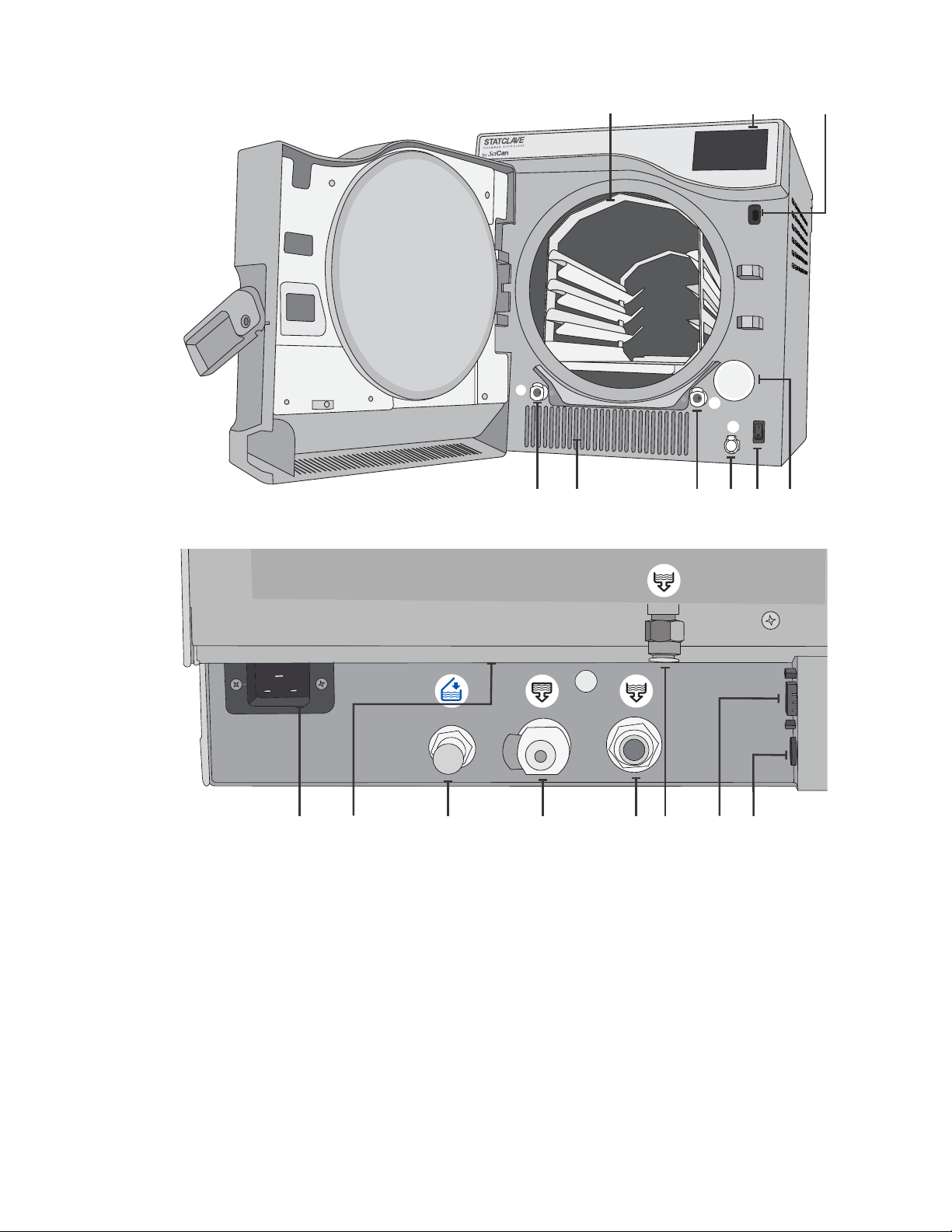
1.4 Unit Overview
7
31
42
8
5126
9
10
1. Venturi reservoir drain quick-connect (OUT)
2. Warm air exhaust
3. Clean water reservoir drain quick-connect (OUT)
4. Clean water reservoir fill quick-connect (IN)
5. Power switch
6. Bacteriological filter
(bacteria-retentive air filter)
7. Chamber rack
8. Touchscreen
9. USB port
11
7
15
13
10. Power cord input
11. Ethernet port (not visible)
12. Auto fill port for clean water reservoir
13. Condenser drain port (to drain for shipping)
14. Overflow drain port for reservoirs
15. Exhaust drain port
16. RS232 port
17. Power port for external fill pump (optional)
14
16 17
Page 10
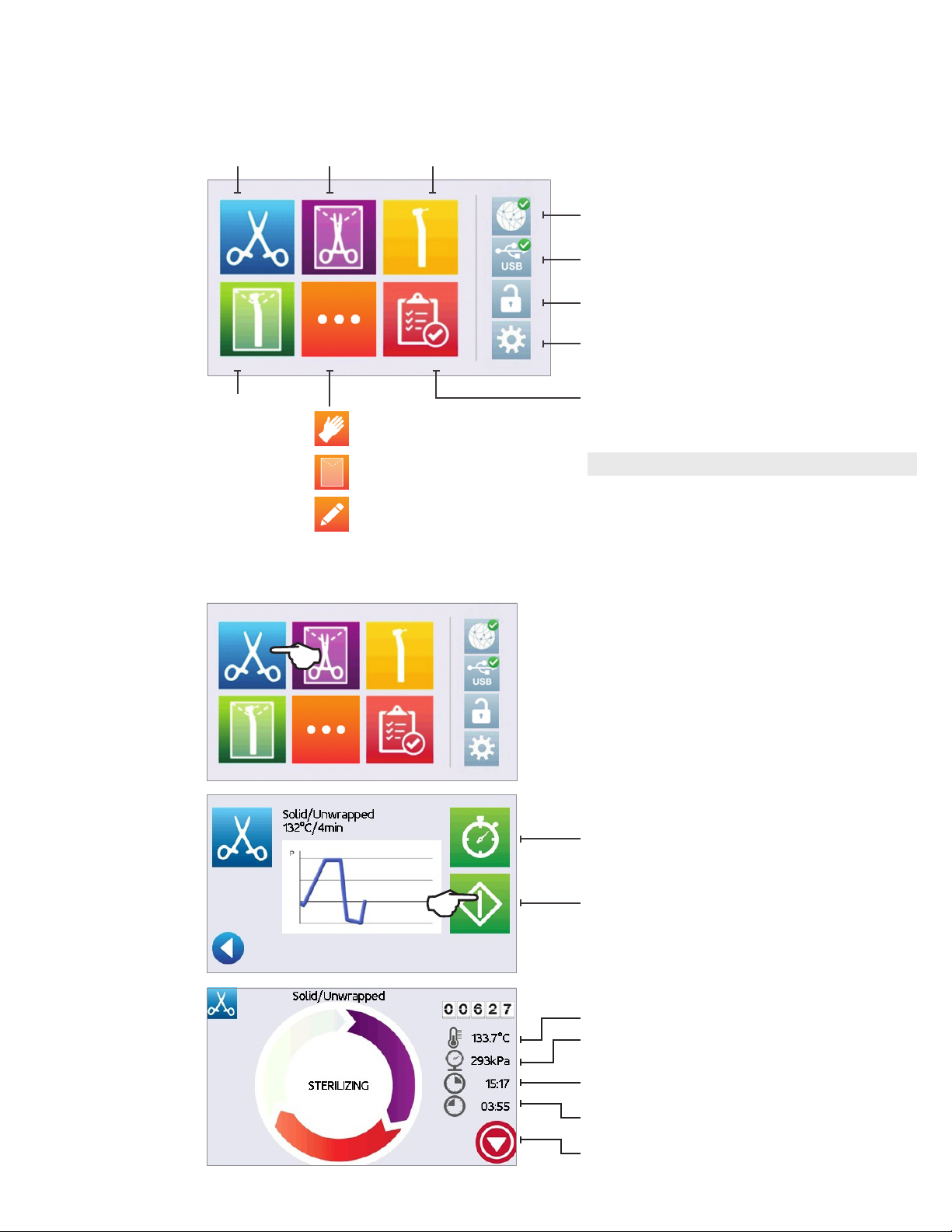
1.5 Touchscreen Overview
Home Screen
Solid /
Unwrapped
Solid /
Wrapped
Hollow /
Unwrapped
System icons:
Connectivity: Access network and Internet.
USB: View cycle history.
Door Lock: Unlock door.
Settings: Access settings menu.
Hollow /
Wrapped
Rubber & Plastic
Textiles/Porous
Custom Cycle
1.6 Using the Operation Screens
Test Cycles
Complete cycle information in Section 7
More inf ormati on on ico ns and sof twar e scree ns in Ap pendi ces A and B .
1. Select a cycle.
2. Press START.
Delayed start
More information in Section 6.3
Start
3. Cycle in progress.
Current chamber temperature
Current chamber pressure
Total time elapsed in the cycle - seen on cycle
screen for entire cycle
Appears during STERILIZATION and DRYING to show
time remaining
Stop
8
Page 11
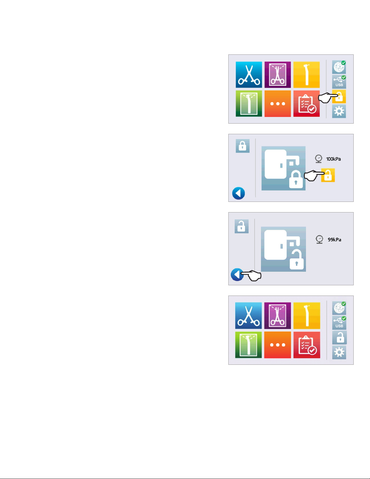
1.7 Unlocking the Door
The STATCLAVE will lock the chamber door when you select a cycle.
To unlock the door, go to the home screen and follow these steps:
1. PRESS lock icon.
2. PRESS unlock icon.
3. PRESS the back icon.
4. Lock icon is now changed to unlocked.
9
Page 12
2. Set Up
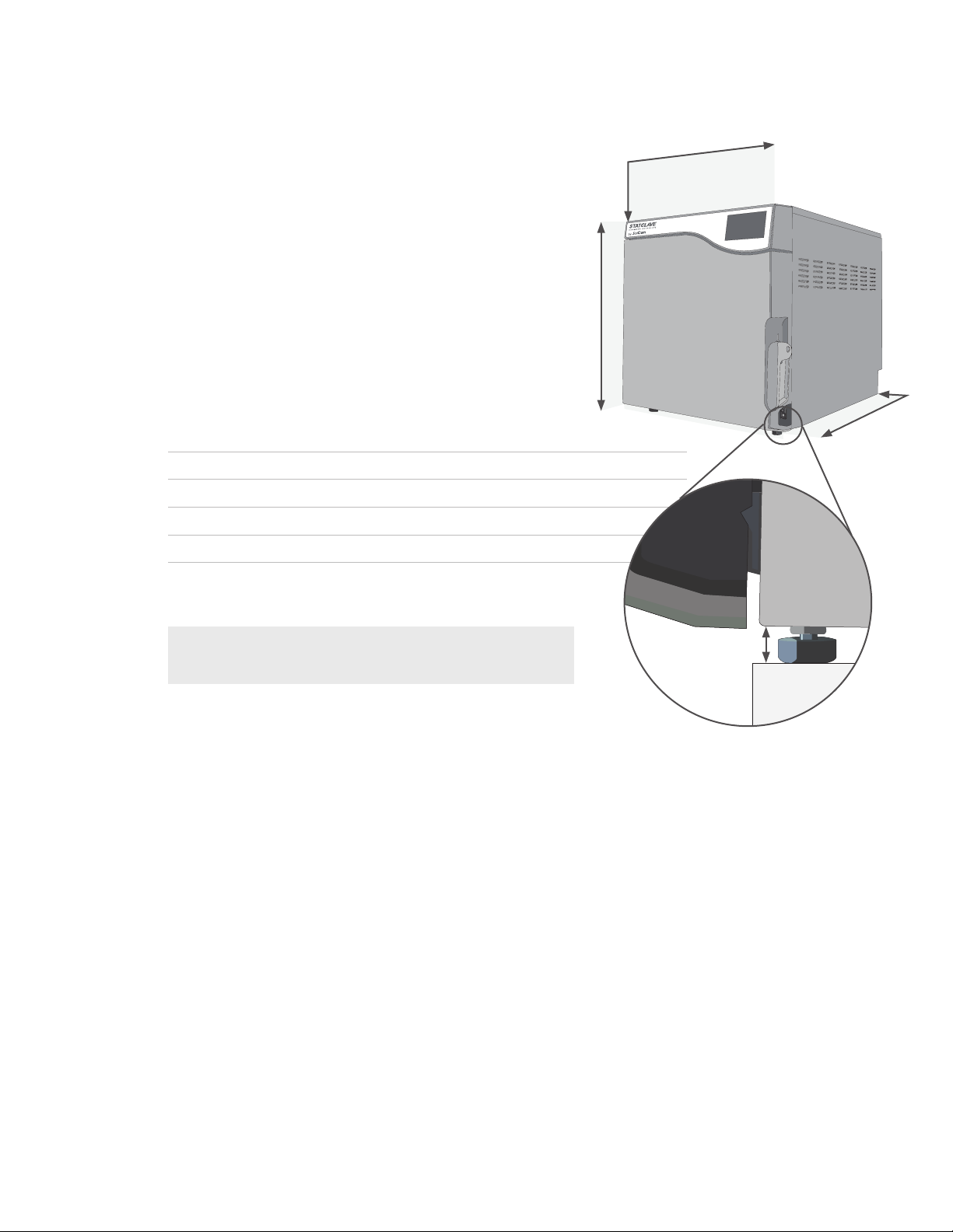
2.1 Installing Your STATCLAVE
› Place the STATCLAVE on a flat level surface
to support a 175 lbs (79.5 kg) load
.
strong enough
› Allow for at least 7” (180 mm) of space ABOVE the unit
to enable access to the reservoirs. If there is less than
7” (180 mm) above the unit, use a screwdriver to remove
the front hinge of the clean water reservoir so that the
reservoir panel can slide in and out of position from the front
of the unit.
› On the right side of the unit, allow for at least 2” (50 mm) of
space for ventilation.
› The unit vents warm air from below the door. Ensure the
door overhangs the level surface.
Unit Dimensions and Operating Environment
Height with front legs retracted 19” / 483 mm
Height with front legs fully extended 19.5” / 495 mm
Width 17.75” / 450 mm
Depth 25” / 635 mm
Weight (empty) 136 lbs/ 61.7 kg
Weight (with full reservoirs and full load) 175 lbs/ 79.5 kg
19”-
19.5”
17. 5 ”
7”
2”
25”
IMPORTANT! To improve drainage, ensure the unit is tilted
toward the back. Use the leveling feet to ensure the front of
the unit is 1” (25 mm) from the level surface.
Temperature and Humidity
Avoid installing your STATCLAVE in direct sunlight or close to a heat source such as vents or radiators. The recommended
operating temperatures are between 5˚C-40˚C / 41˚F-104˚F with a maximum humidity of 80%.
Electromagnetic Environment
Your STATCLAVE has been tested and meets applicable standards for electromagnetic emissions. While your unit does not
emit any radiation, it may itself be affected by other equipment that does. We recommend that your unit be kept away from
potential sources of interference.
1” gap
10
Page 13
2.2 Connecting and Powering Your STATCLAVE
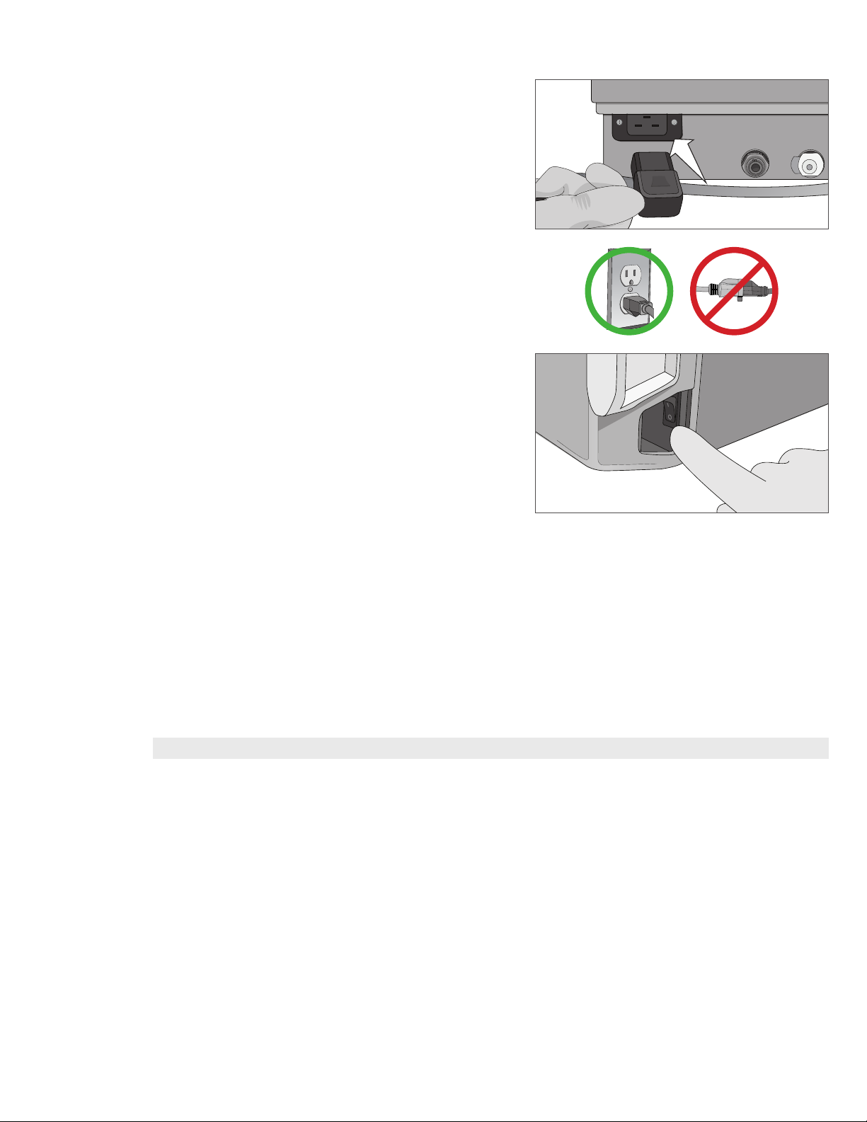
1. Ensure the power switch at the front right of the unit is in
the OFF position and connect the power cord supplied
to the power port at the back of the unit.
2. Connect directly to a power source.
Don’t use an extension cord.
3. Turn ON the power switch located at the front right of
the unit.
Electrical Connections
To power your unit, use properly grounded and fused power sources with the same voltage rating as indicated on the serial
number label at the back of your STATCLAVE.
› DO use an outlet that is protected by a 15A breaker.
› DO use a dedicated circuit, single phase 120 V~ 60Hz, 12A or 208-240 V~60Hz, 12A, depending on the voltage rating
indicated on the serial number label at the back of your unit.
Unit Electrical Characteristics:
› Protection class 1 device.
› Maximum power consumption of the autoclave is 1,440 Watts for 120V and 2,250-3,000 Watts for 208-240V.
2.3 Connecting Your STATCLAVE’s Water Draining System
IMPORTANT!
The STATCLAVE uses water from the Venturi reservoir to generate vacuum draws at the beginning and end of each cycle. For
the unit to operate, BOTH the clean water reservoir and the Venturi reservoir must contain the minimum required water levels.
When the chamber releases steam it travels through the condenser and drains from the condenser exhaust tube. Excess water
in both the Venturi reservoir and the clean water reservoir drains from the reservoir overflow tube. BOTH elbow fittings at the
back of the unit must be connected to a water draining system.
For the unit to function, BOTH reservoirs must be full and BOTH drain tubes must be connected.
11
Page 14
Connecting Directly to a Drain
Any new central drain point installation should be done by a technician. The drain points (C) must be located on the upper
portion of vertical drain pipe ABOVE the P-trap.
For direct-to-drain connections, you will need to use the direct-to-drain hardware (provided with the unit).
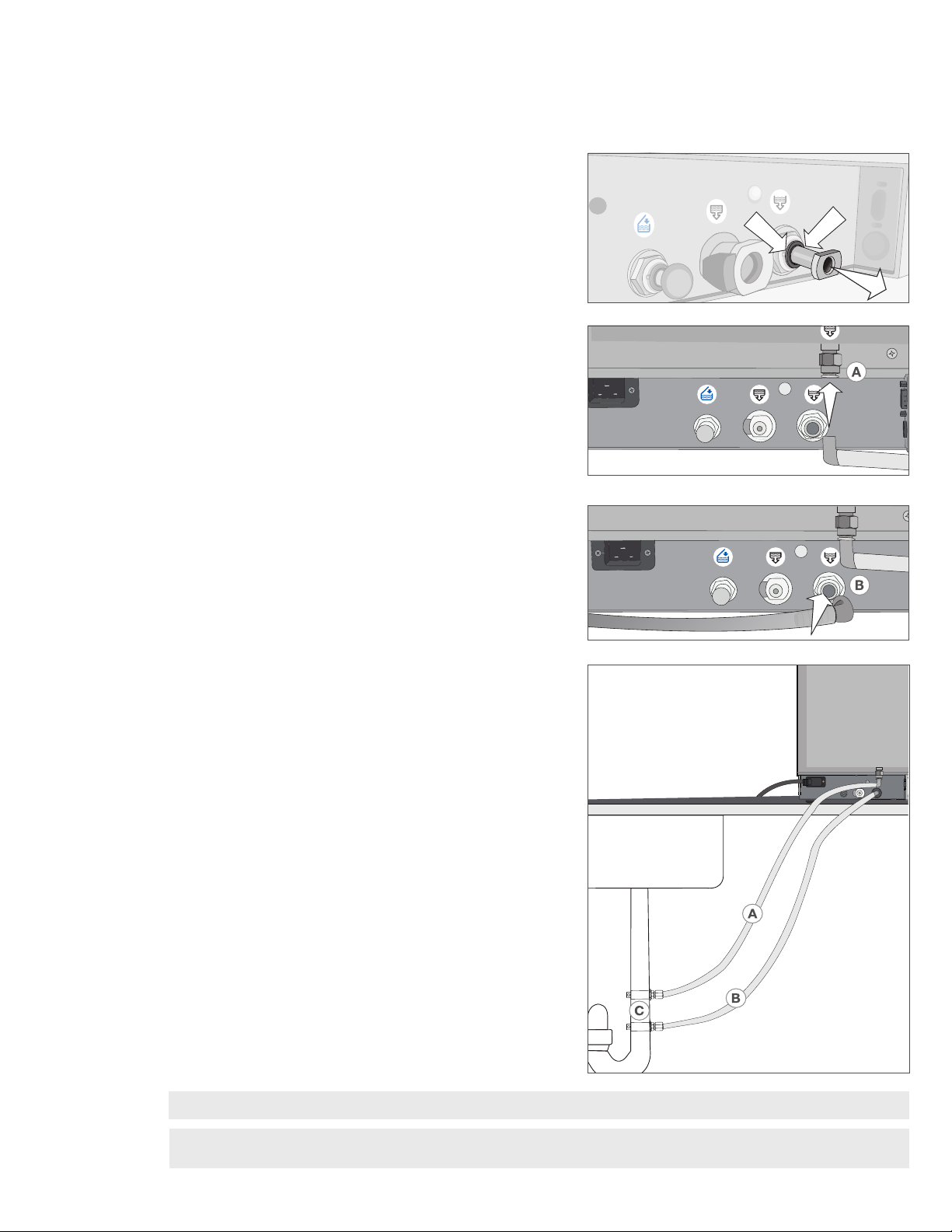
1. The unit is shipped with plugs in its ports. To remove a
plug, apply even pressure to the Inner Ring holding it
down on either side of the plug and pull out the plug.
2. Insert one elbow connector with silicone tube to the
metal exhaust port (A).
3. Insert the other elbow connector with silicone tube to
the plastic reservoir overflow
drain port (B).
4. Connect the exhaust tube with elbow fittings (A) to the
port installed on the drain pipe (C).
5. Connect the reservoir overflow tube (B) to the remaining
port on the drain pipe (C).
IMPORTANT! Avoid excess sagging in the lines; cut both tubes to measure.
IMPORTANT! Tubes should not be kinked, bent or otherwise obstructed. The connection point to the central drain
must be lower than the autoclave’s support surface otherwise the reservoirs may not drain correctly.
12
Page 15
Connecting the Waste Bottle
The unit is shipped with a waste bottle in case a direct-to-drain installation is not possible. To use the waste bottle, follow these
steps:
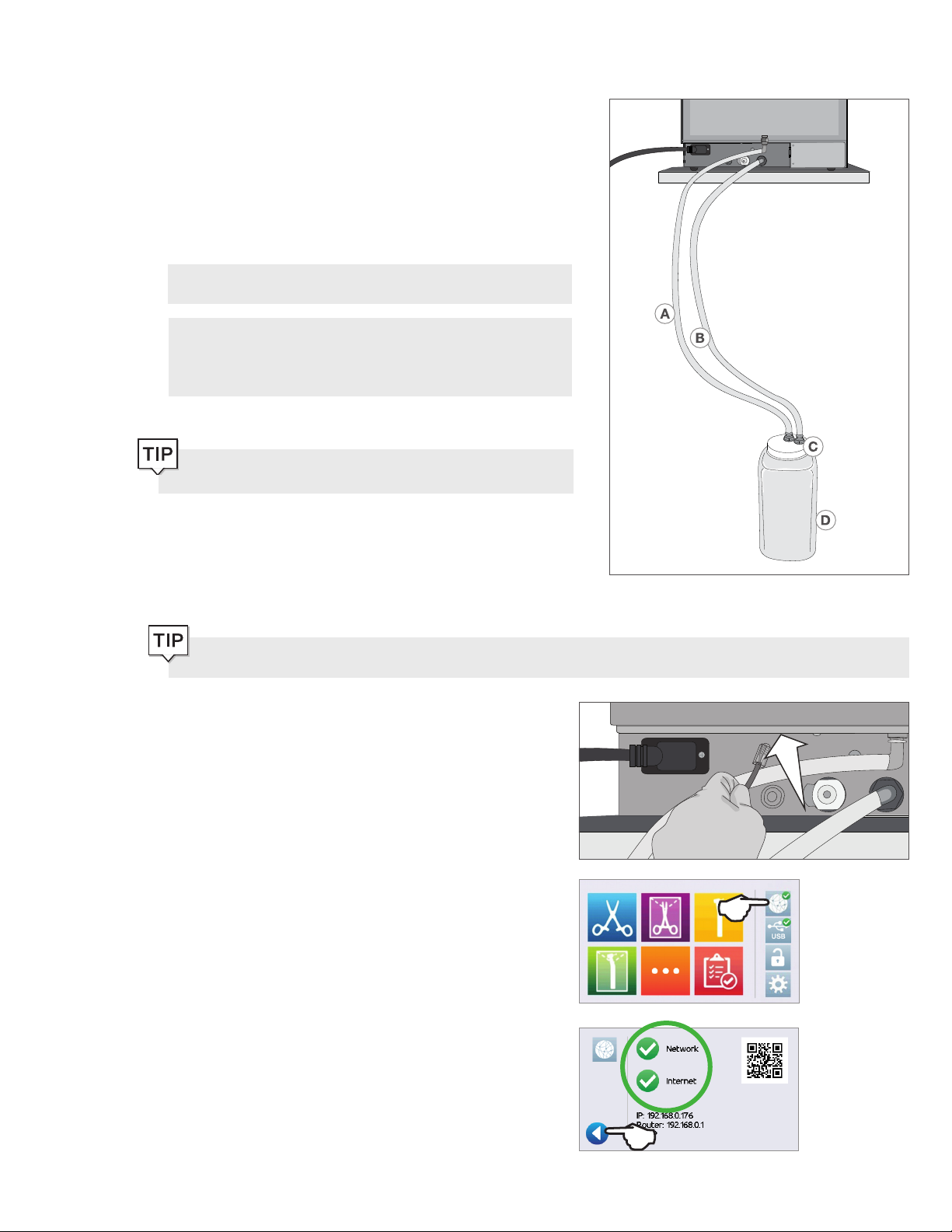
1. Set the waste bottle (D) on the ground or in the
cabinetry below the unit.
2. Connect the exhaust tube (A) to a port on the waste
bottle cap (C).
3. Connect the reservoir overflow tube (B) to a port on the
waste bottle cap (C).
IMPORTANT! Avoid excess sagging in the lines; cut both
tubes to measure.
IMPORTANT! Tubes should not be kinked, bent or
otherwise obstructed. The waste bottle must be lower than
the autoclave’s support surface otherwise the reservoirs
may not drain correctly.
Add a small amount of water to the empty waste bottle to
give it stability.
2.4 Connecting your STATCLAVE to a Network
Connecting to a Wired Network
Do you want to drain the unit prior to shipping or cleaning? For instructions on how to completely drain both
reservoirs for cleaning or shipping, see Sections 10.6 and 10.14.
1. Connect Ethernet cable to port at back of unit.
2. From the home screen select the CONNECTIVITY icon.
3. Confirm that the unit is connected to both the Network
and Internet and press the back icon to return to
the home screen.
13
Page 16
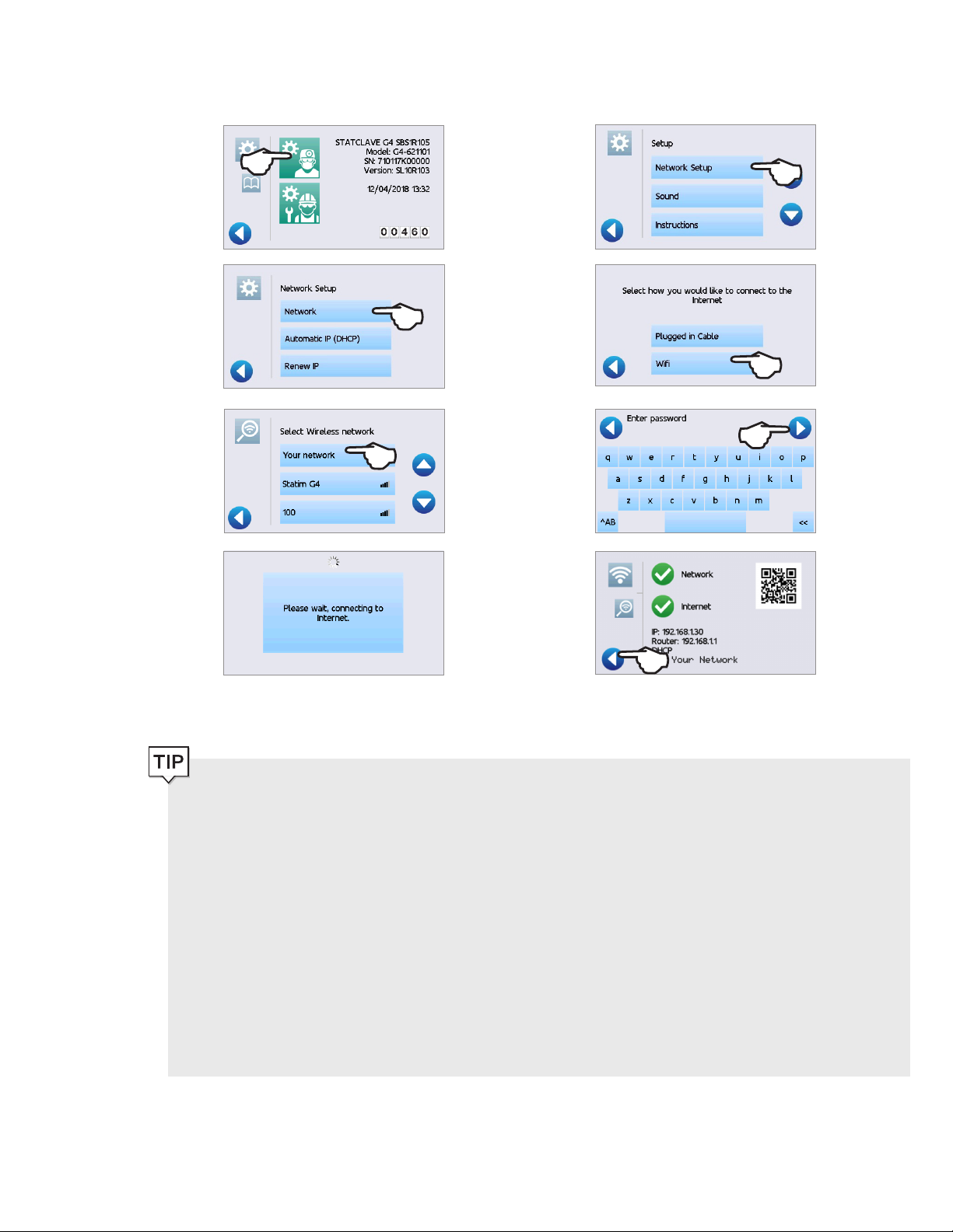
Connecting to a Wireless Network
From the unit’s home screen, select the SETTINGS icon, then follow these steps:
1. 2.
3. 4.
5. 6.
7. 8.
Data Security and WiFi
Ensuring your WiFi® connections are secure is an important element of safeguarding your organization’s data. A WiFi
network using WPA2™ provides both security (you can control who connects to it) and privacy (the transmissions
cannot be read by others) for communications as they travel across your network. For maximum security, your
network should include only devices with the latest in security technology – WiFi Protected Access® 2 (WPA2).
Tips for securing your network
Change the network name (SSID) from the default name.
Change the administrative credentials (username and password) that control the configuration settings of your Access
Point/Router/Gateway.
Enable WPA2-Personal (aka WPA2-PSK) with AES encryption.
Wireless transmission considerations
To comply with Federal Communications Commission and Industry Canada Radiofrequency exposure compliance
requirements, the antenna used for this transmitter has been installed to provide a separation distance of at least 20
cm from all persons and must not be co-located or operating in conjunction with any other antenna or transmitter.
(The transmission antenna for the wireless card is located in the front fascia.)
For the STATCLAVE Cybersecurity Statement, see Appendix C.
14
Page 17
3. Getting Started
Preparing Your STATCLAVE for Use
Once the STATCLAVE has been correctly installed, and before using it for the first time, make sure BOTH the clean water and
Venturi reservoirs contain distilled water. The STATCLAVE uses water from the Venturi reservoir to generate vacuum draws at
the beginning and end of each cycle. Both reservoirs must contain the minimum required water levels for the unit to function.
IMPORTANT! DON’T run the STATCLAVE without the chamber rack in place.
1. Power on the unit.
2. Follow the screen prompts to connect your STATCLAVE
using either WiFi or an Ethernet cable connection. This
will automatically set the time and date for your unit.
If you do not wish to connect your STATCLAVE at this time, Press the FORWARD icon and select a language. Then
press the FORWARD icon and the SKIP icon to scroll to the end of the introduction. You must Agree or Disagree
with the Privacy Policy to get to the home screen. (For more information on the Privacy Policy screen see Section 8.
Using and Changing Settings.)
From the home screen, select the SETTINGS icon then the USER icon and then the GENERAL button to access
the menu for time, date, country, and time zone. (See Section 8 Using and Changing Settings)
(SciCan recommends connecting and registering your STATCLAVE. To do this at a later time, see Section 8.5
Registering for STATCLAVE Online Access.)
15
Page 18
3. Open the clean water reservoir located on the top right
of the unit. Using a large container, fill with distilled water
to the maximum fill level line or until you hear 3 BEEPs.
(For more fill options see Section 4. Filling the Water
Reservoirs.)
4. Open and fill the Venturi reservoir to the maximum fill
level.
5. Open the door, plug the USB storage device into the
USB port.
CAUTION! Hot Chamber.
The unit’s Stand-by mode is preset to maintain a hot
chamber.
6. Make sure the bacteriological filter is securely in place.
7. Check your national and local guidelines for any
additional protocols and tests required before using
your unit.
16
Page 19
4. Filling the Water Reservoirs
Normal operation of the STATCLAVE requires a minimum amount of distilled water in BOTH the clean water reservoir and
Venturi reservoir.
To fill the Venturi reservoir:
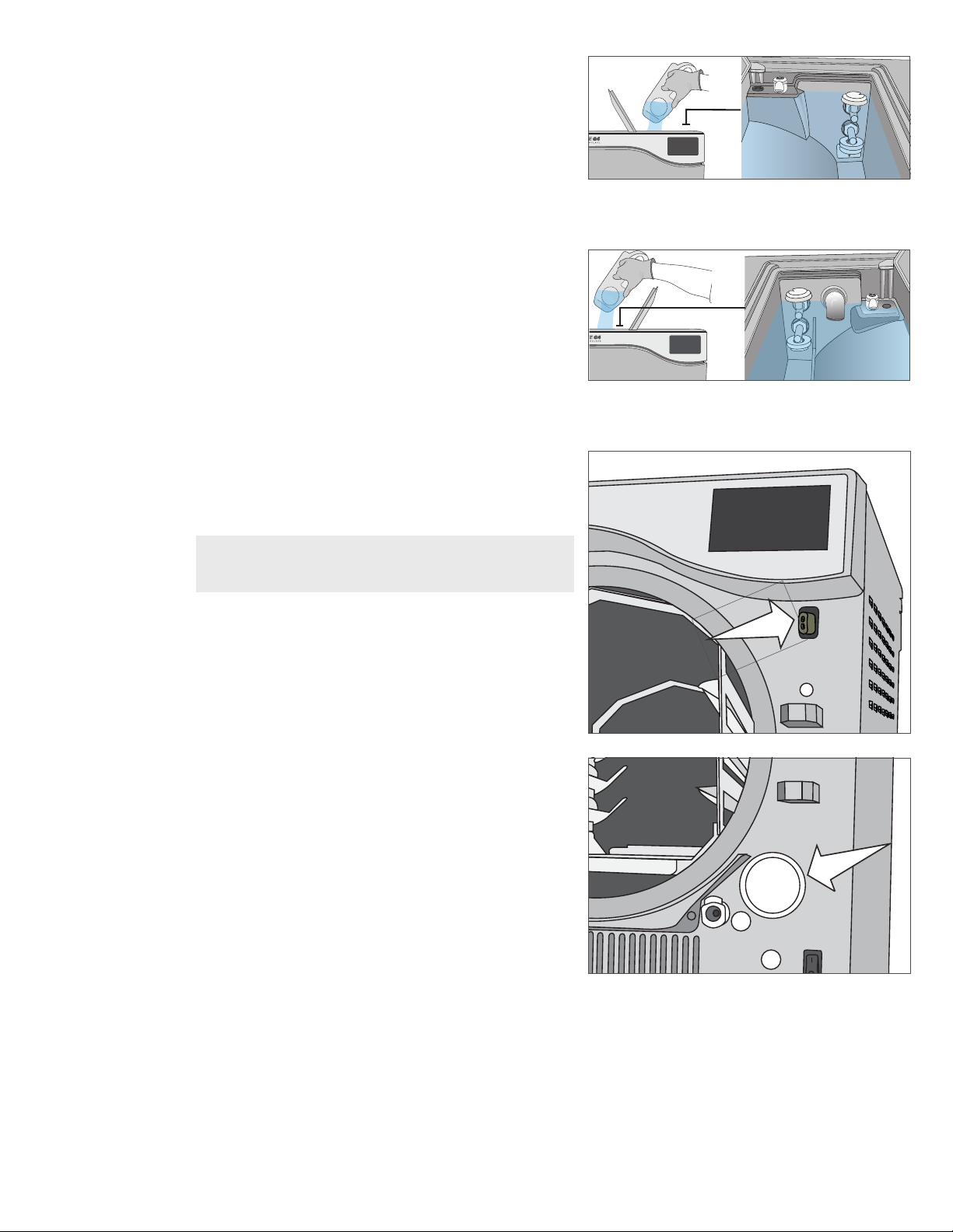
1. Open the Venturi reservoir lid located on the top left of
the unit.
2. Fill it with distilled water to the maximum fill line
indicated in the reservoir.
When filling the Venturi reservoir for the first time,
you will need to add an additional
0.5 US gal / 2 L of water. This will fill the steam cooling
system’s condenser. To do this, simply fill the Venturi
reservoir to the maximum fill line and wait as the
Venturi reservoir water fills the condenser, then top up
the Venturi reservoir to the maximum fill line again.
Setting the water reservoir filling mode
Your STATCLAVE’s default filling option is MANUAL. If you are manually filling the reservoir, you do not need to change the
unit’s fill option settings.
If you are connecting your STATCLAVE to an external filling device such as a VistaPure specialized water filtration system or
external water tank and auxiliary pump, make sure your unit is set to the AUTOMATIC filling mode.
To change this setting from the home screen, select SETTINGS then USER and then follow these steps:
1. 2.
To fill the clean water reservoir, there are four different methods:
› Manual filling using RESERVOIR TOP.
› Manual filling using the FRONT QUICK CONNECTOR.
› Automatic filling using VISTAPURE SPECIALIZED WATER FILTRATION SYSTEM with accumulation tank.
› Automatic filling using an EXTERNAL WATER TANK AND AUXILIARY PUMP.
17
Page 20
4.1 Manual Filling Using Reservoir Top
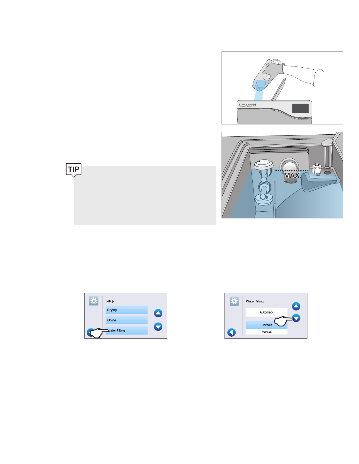
1. With the unit powered ON, flip open the clean water
reservoir lid located on the top right of the unit.
2. Using a large container, fill with distilled water to the
maximum fill line or until you hear three BEEPs.
When adding water for the first time, the reservoir may
take up to 1 US gal / 4 L.
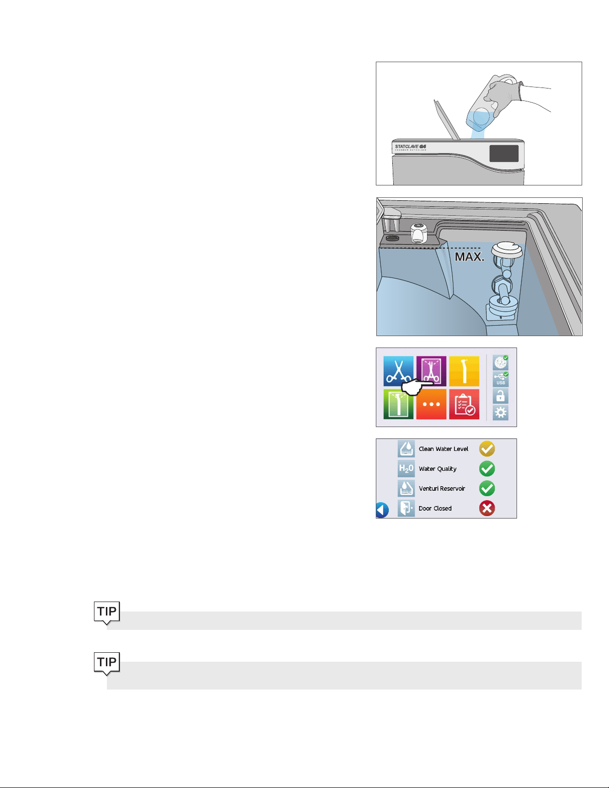
3. With the door open, select any cycle from the LCD’s
home screen to view the pre-cycle information screen.
4. The clean water level check mark will turn yellow when
the minimum water level is reached and green when the
reservoir is filled to the maximum level.
You can start a cycle if water level icons are either yellow or green.
If your unit is not directly connected to the drain, empty the waste bottle regularly or each time you are filling the
clean water reservoir.
18
Page 21
4.2 Manual Filling Using Quick Connector at Unit Front
The front fill quick connector is for the refilling of the clean water reservoir. The Venturi reservoir does not have a front fill quick
connector because it is only filled on installation or after cleaning.
1. To use this method, you will need the manual fill
container (0.5 US gal / 2 L) with quick connect and
tubing (sold as an accessory).
2. Fill the accessory container with distilled water, keeping
it horizontal.
3. With the unit powered ON, connect the tube’s quick
connector to the unit’s clean water fill port at the front.
4. Hold or place the manual fill container at a level higher
than the unit’s fill port and loosen the cap on the
container to allow water to flow into the tank.
5. With the door open, access the LCD’s home screen
and select any cycle to view the pre-cycle information
screen.
6. The clean water level check mark will turn yellow when
the minimum water level is reached.
You can start a cycle if water level icons are either yellow or green.
7. Repeat this procedure a second time to fill the water
reservoir to max level. (Each fill takes 4 minutes.)
Continue until the clean water level
and you hear three
If your unit is not directly connected to the drain, empty the waste bottle regularly or each time you are filling the
clean water reservoir.
BEEPs.
indicator turns green
19
Page 22

4.3 Automatic Filling Using a VistaPure Specialized Water Filtration System
with Accumulation Tank
When connecting your STATCLAVE to an external filling device such as a VistaPure specialized water filtration system, make
sure your unit is set to the AUTOMATIC filling mode. (See Section 4. Setting the water reservoir filling mode.)
1. Remove the plug from the automatic fill port (A) at the
back of the unit.
2. Connect the water filtration system’s Teflon tube (or
other suitable tube) to the automatic fill port (A) at the
back of the unit.
3. Ensure the tube runs freely from the water filtration
system. It should not be sharply bent, crushed or
obstructed in any way.
4. Open the valve on the water filtration system (C) to
fill the accumulation tank.
5. Open the accumulation tank’s (B) valve to facilitate the
flow of water to the STATCLAVE.
6. Go to the home screen and select any cycle to activate
the filling system.
IMPORTANT! Before you activate the AUTOMATIC filling mode, make sure the external tank has been filled with high
quality distilled water. Also remember to open the tap on the external tank or filtration system, if required.
IMPORTANT! When selecting an automatic filling option, it is best to use a direct-to-drain waste connection. Use of
an external waste bottle will require careful monitoring and frequent emptying.
High quality distilled water with a conductivity of 6.4 ppm / 10 µS/cm or less is recommended.
20
Page 23

4.4 Automatic Filling Using External Water Tank and Auxiliary Pump
When connecting your STATCLAVE to an automatic filling system such as an external water tank and auxiliary pump, make
sure your unit is set to the AUTOMATIC filling mode. (See Section 4. Setting the water reservoir filling mode.)
An input hose can be connected to the STATCLAVE from
an external tank that uses an automatic water pump to feed
the internal tank automatically when it reaches the MIN level.
Be sure to monitor the water level of your external tank. The
STATCLAVE unit does not monitor the water level in the
external tank and the auxiliary water pump should not run dry.
To use this method, you will need the STATCLAVE automatic
fill pump (sold as an accessory) and an external tank with a
minimum diameter opening of 2” (50mm) through which you
can insert the pump.
To connect the automatic fill pump to the STATCLAVE,
follow these steps:
1. Remove the plug from the automatic fillport(A) at the
back of the unit.
2. Connect the fitting at the end of the pump’s tubing to
the automatic fill port (A).
3. Connect the automatic fill pump’s power source to the
power connection (B) located at the back of the unit.
4. Fill the external tank (C) with distilled water.
5. Place the submersible automatic fill pump (D) in the
external tank.
6. Go to the home screen and select any cycle to activate
the filling system.
21
Page 24

5. Loading Instruments
Before loading any instruments into the STATCLAVE, consult the instrument manufacturer’s reprocessing instructions to
confirm instruments can tolerate steam sterilization temperatures.
The following material can typically be sterilized with steam:
› Stainless steel surgical/generic instruments
› Carbon steel surgical/generic instruments
› Rotating and/or vibrating instruments driven by compressed air (turbines) or
mechanical transmission (counter-angles, tooth scalers)
› Glass articles
› Mineral-based articles
› Articles made of heat-resistant plastic
› Articles made of heat-resistant rubber
› Heat-resistant textiles
› Medical textiles (gauze, pads, etc.)
CAUTION! DON’T use the STATCLAVE to sterilize liquids or pharmaceutical products.
This may result in incomplete sterilization and/or damage to the autoclave.
Clean Instruments Before Sterilization
It is important to clean, rinse and dry all instruments before loading them into the autoclave. Disinfectant residues and solid
debris may inhibit sterilization and damage both the instruments and the STATCLAVE. Lubricated instruments must be wiped
thoroughly and any excess lubricant removed before loading.
STATCLAVE LOAD CAPACITIES
Load Type Capacity per Tray Capacity per Pouch Rack Total Capacity*
Solid Items 1. 5 kg 3 kg 6 kg
Rubber and Plastics 0.5 kg Not applicable 2 kg
Dental Handpieces 1.5 kg 3 kg 6 kg
Textiles and Packs Not applicable Not applicable 2 kg
* Load capacities listed here are for the total weights of instruments and cassettes or containers not supplied with the unit.
DON’T include the weight of the chamber rack, trays, pouch rack or drying plates that are supplied with the unit when calculating
your instrument load weights.
22
Page 25

5.1 Using the Chamber Rack
IMPORTANT! DON’T run the STATCLAVE without the chamber rack in place.
Inserting the Rack
Push the rack into the chamber until it locks into position at the
back. The front of the chamber rack should be flush with the
chamber flange.
CAUTION! Hot Chamber.
Using the Rack
1. Tray Configuration
2. Pouch Configuration
3. Cassette Configuration
23
Page 26

5.2 Wrapped Instruments
If you plan to store your instruments after sterilization, wrap them according to the instrument manufacturer’s instructions,
select the appropriate wrapped cycle and allow it to run to completion. Unwrapped instruments, once exposed to ambient or
external conditions, cannot be maintained in a sterile state.
› DO ensure to use only sterilization wraps and
pouches that have been cleared for your market.
IMPORTANT! To ensure optimal drying when using pouches, SciCan recommends the use of the STATCLAVE
pouch racks supplied with your unit.
Using Pouches
1. Position pouches with the paper side towards the tall
support on the pouch rack. This will optimize drying.
2. Arrange pouches 2 per row to a maximum of 10
pouches to a rack.
3. Load one pouch rack on the bottom rail and the other
on the second from top rail.
› DON’T use 100% cellulose sterilization wraps as
these may require longer drying times.
CAUTION! Instruments in pouches or wraps that are not completely dry must be used immediately or reprocessed.
› DO use the STATCLAVE pouch racks supplied with your
unit to position pouches on their sides.
› DO always check that pouches are placed correctly: with
the paper side against the rack’s tall supports.
› DO package instruments individually. If you are placing
more than one instrument in the same pouch, ensure they
are made of the same metal.
› DO always use the tray extractor tool provided to remove
the pouch rack from the unit.
24
› DON’T stack pouches or wraps. Instead, use the
pouch rack to keep pouches vertical. This will
promote drying and enable effective sterilization.
› DON’T store pouched or wrapped loads that are
wet. If the wraps on the wrapped load are not dry
when the load is removed, the instruments must be
handled in an aseptic manner for immediate use or
re-sterilized.
Page 27

Using Wrapped Cassettes and Containers
Drying plates must be used when processing wrapped cassettes to ensure air flow around cassettes and to promote proper
drying.
For wrapped loads, place a chemical indicator inside each of the wrappings.
Inserting drying plates
1. Remove the wire trays from the unit and insert the
drying plates into each of the slots in the base of the
rack.
2. The three plates should sit vertically, evenly placed in
the rack with the taller end pointing up and at the back
of the chamber.
3. Place cassettes vertically into the unit to optimize
drying.
When Using Wrapped Cassettes:
› DO ensure you always use suitably porous material (sterilization paper, muslin napkins, etc.) and close the wrapping
with adhesive tape designed for use in autoclaves.
› DO ensure there is space for sufficient air flow between cassettes when loading more than one wrapped cassette per
row.
› DO always use adhesive tape designed for autoclaves or heat-sealing machines. Using staples, pins or other fasteners
could compromise the sterility of the load.
› DO be sure to insert wrapped cassettes with the flat side down to avoid tearing the wrap.
25
Page 28

Using Rigid Sterilization Containers
The STATCLAVE is capable of processing re-usable rigid sterilization containers, which can be used as an alternative to
wrapping cassettes. These provide a convenient way to organize and store instruments, and cut down on the waste involved
with using paper wraps. Check the sterilization container manufacturer’s instructions to determine its suitability for pre-vacuum
steam sterilization.
When Using Rigid Sterilization Containers:
› DO ensure drying plates are used and that the rigid
sterilization containers are placed vertically in the rack
to promote proper drying. (See Inserting drying
plates, above.)
› DO ensure there is space for sufficient air flow
between the rigid sterilization containers when loading
more than one container per row.
5.3 Unwrapped Instruments
Unwrapped instruments are also referred to as Immediate Use Instruments because once exposed to ambient or external
conditions, they cannot be maintained in a sterile state. If you plan to store your instruments after sterilization, wrap them
according to the instrument manufacturer’s instructions, select the appropriate wrapped cycle and allow it to run to completion.
› DO use the trays provided with your unit to hold
unwrapped instruments.
› DO always use the trays with the chamber rack provided.
› DO always use the tray extractor provided to remove trays
from the sterilization chamber.
› DO arrange instruments made of different metals
(stainless steel, tempered steel, aluminum, etc.) on
different trays or keep them well separated from
each ot h e r.
› DO arrange receptacles upside down to prevent water
from pooling inside.
› DO ensure objects on trays are always arranged with
some distance between them ensuring they will remain
in the same position for the entire sterilization cycle.
› DO ensure that hinged instruments are sterilized in
an open position.
› DO position cutting instruments (scissors, scalpels, etc.)
so that they do not come into contact with each other
during sterilization.
› DON’T load the trays beyond their maximum indicated
limit. (See STATCLAVE Load Capacities chart at the start
of Section 5. Loading Instruments)
› DON’T stack trays or put them in direct contact with the
sterilization chamber walls.
26
Page 29

5.4 Rubber and Plastic
The following materials CAN be sterilized in the STATCLAVE:
› Nylon, polycarbonate (Lexan™), polypropylene, PTFE
(Teflon™), acetal (Delrin™), polysulfone (Udel™),
polyetherimide (Ultem™), silicone rubber, and polyester.
When loading rubber and plastic tubing on the tray, make sure
they do not touch the chamber walls. This ensures that steam
reaches all surfaces, and will promote drying.
› DO arrange receptacles upside down to prevent water
from pooling inside.
› DO process dental impression trays on the top tray to
optimize drying.
› DO process on the top tray any items with shapes that
could collect water.
Additional tips for rubber and plastics:
Arrange the tubing on the tray so that ends are not obstructed or crushed.
DON’T bend or wind tubes. Allow tubes to lie as straight as possible.
IMPORTANT! DON’T attempt to sterilize the following materials in the STATCLAVE:
Polyethylene, ABS, styrene, cellulosics, PVC, Acrylic (Plexiglas™), PPO (Noryl™), latex, neoprene, and similar
materials.
Use of these materials may lead to instrument or equipment damage. If you are unsure of your instrument’s material
or construction, do not sterilize it in your STATCLAVE until you have checked with the instrument manufacturer.
5.5 Textiles and Surgical Packs
Carefully wash and dry textile materials (or porous materials
in general), such as smocks, napkins, caps and other, before
treating these in the autoclave. Do not use detergents with a
high content of chlorine and/or phosphates and do not bleach
with chlorine-based products. These substances can damage
the tray supports, trays and any metal instruments that may be
present in the sterilization chamber.
5.6 Using Biological and Chemical Indicators
Use chemical process monitors suitable for autoclaves/steam sterilizers at the indicated cycle temperatures and times in
or on each package or load being sterilized. For biological indicator usage and frequency, follow the indicator manufacturer’s
instructions and your local regulations, guidelines and standards.
27
Page 30

6. Using Your STATCLAVE
6.1 Running a Cycle
Once the autoclave has been correctly installed and before using your STATCLAVE for the first time, make sure BOTH the clean
water reservoir and Venturi reservoir are full. Refer to Section 4. Filling the Water Reservoirs for detailed instructions.
1. Power on the unit
The main switch is located below the
door handle.
2. Ensure both reservoirs are full
You will not be able to start a cycle if the reservoir levels are
below the minimum fill lines.
3. Open the door
The LCD should display the UNLOCKED icon. Pull up
on the handle to disengage the manual latch and open
the door. If the door will not open, press the LOCK
icon to go to the door lock status screen and press the
UNLOCK icon.
CAUTION! Hot chamber.
The unit’s Stand-by mode is preset to maintain a hot chamber.
To avoid burns, take care not to touch the chamber, rack or door with bare hands.
4. Load the instruments
Refer to Section 5. Loading Instruments for detailed
instructions
28
Page 31

5. Close the door
Close the door by locking the handle into position.
When you close the door, you will hear the sound of the
vacuum system adjusting chamber pressure to seal the
door. This is a normal operating sound.
6. Select the cycle
From the LCD, select the cycle you want to run. To
learn more about the available cycles, see Section 7.
Sterilization Cycles.
Press the icon to see the cycle name and parameters.
If User PIN ID has been enabled, you will be prompted to enter your User ID and PIN before your cycle selection is
accepted.
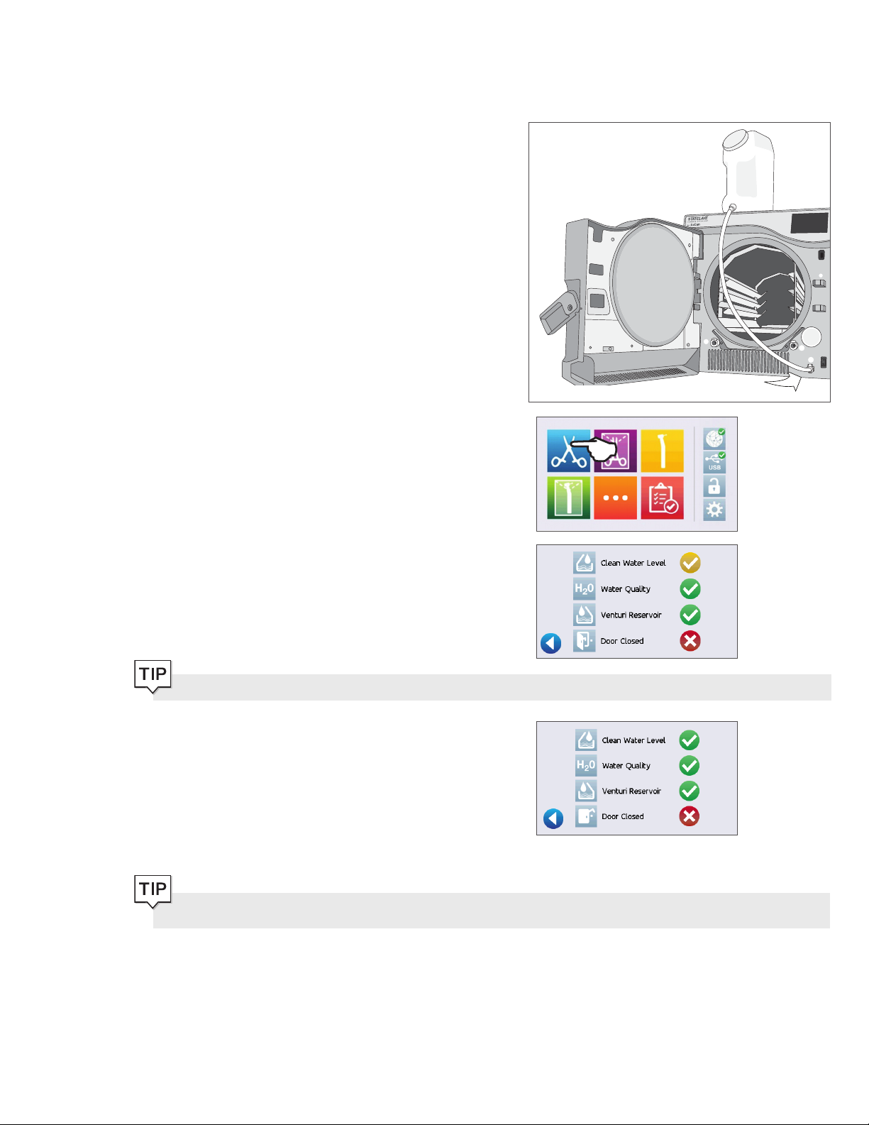
If there is a problem with the door lock or water, a PRECYCLE SCREEN will appear:
Clean water level low. Add water.
There is a water quality problem. Press icon to view detail.
Venturi water reservoir level low. Add water.
There is a problem locking the door. Check for instruments
jamming the door.
7. Press the START icon
If the chamber is cold, warming up can take up to 12
minutes.
Allow the cycle to run to completion.
IMPORTANT! When the drying stage is finished, the display will show the cycle is complete.
8. Cycle is complete.
When the cycle is complete, press the STOP icon to
release the load.
29
Page 32

9. Remove the load
Open the door. Remove the trays or pouch racks using
the tray extractor provided with the unit.
CAUTION! The metal parts will be hot.
6.2 Stopping a Cycle
CAUTION!
If the screen displays a CYCLE FAULT code or a NOT STERILE message, the contents are not sterile. See Section
11 Troubleshooting for more information.
If the wraps on the wrapped instruments are not dry when the load is removed, the instruments must be handled in
an aseptic manner for immediate use or re-sterilized.
To stop a cycle BEFORE sterilization is complete, press the
STOP icon at the bottom right of the touchscreen:
1. If you stop the cycle before sterilization is complete,
the unit will remind you that the load is NOT STERILE.
2. Press the STOP icon to continue.
To stop a cycle DURING the drying phase, press the STOP
icon at the bottom right of the touchscreen:
1. If you stop the load during the drying phase, the unit
will remind you to CHECK FOR DRYNESS.
2. Press the STOP icon to continue.
30
Page 33

Opening the door after pressing STOP
Once a cycle has been stopped, the STOP button must be pressed before another cycle can be started. To start a new cycle
or to open the door:
1. Press the STOP icon to continue.
2. Press the LOCK icon.
3. Press the UNLOCK icon.
Press the BACK icon to return to the home screen.
If Process Enforced usage is enabled, you will be prompted to enter your User ID and PIN before opening the
door. A non-registered user can open the door by pressing the SKIP icon.
6.3 Using the Delayed Start
1. Select any cycle.
2. Press the DELAYED START icon.
3. Enter the number of hours and minutes for the delayed
start.
Press the FORWARD icon to begin the countdown.
Press the BACK icon to stop and reset countdown.
The LCD will remain in countdown mode until the cycle
begins.
31
Page 34

6.4 Emergency Door Opening
The STATCLAVE is equipped with a safety mechanism that automatically regulates the chamber pressure when the unit loses
power. (The unit will take approximately 2 minutes to depressurize. Without power, the door lock will remain engaged.)
To unlock the door without power, follow these steps:
1. Remove the emergency door unlocking pin located
in the handle of the tray extractor supplied with your
STATCL AVE
2. Insert the emergency door unlocking pin into the small
hole on the side of the unit’s handle. Push the pin into
the hole as far as it goes to trigger the door release.
3. Remove the emergency door unlocking pin from the
hole in the door handle.
4. Pull up on the handle to open.
CAUTION! Risk of Injury.
Do not force the door handle. If the unit is locked due to a cycle fault, do not force the door handle. Power OFF the
unit and allow it to cool for 10 minutes before attempting again.
32
Page 35

6.5 Running a Bowie-Dick Test
The BOWIE-DICK test is used to ensure proper air removal is occurring in a pre-vacuum autoclave. Complete air removal is
important because pockets of cool air remaining in the chamber can compromise sterilization. The Bowie-Dick test runs a
cycle at 134°C / 273°F for 3.5 minutes to evaluate the correct air removal.
To perform a Bowie-Dick test, you will need a Bowie-Dick device or test pack. These are NOT supplied with your STATCLAVE.
To perform the test, follow the instructions provided by the test pack manufacturer.
Generally, the process is as follows:
1. Open the unit’s chamber door to insert a Bowie Dick
test pack. (Position pack at centre back.)
2. Close and lock the door.
3. From the home screen, select the TESTS icon.
4. To run a Bowie Dick Test, press the BD icon.
5. Press the START icon.
Allow the test to run to completion.
6. Press the STOP icon to release the load.
Follow the test manufacturer’s instructions to interpret
the test results.
If the unit passes the test, it is ready for use. If the unit fails,
check the test manufacturer’s instructions and repeat the test.
33
Page 36

Presetting your Bowie-Dick test
To schedule a Bowie-Dick test before the start of the next working day, use the delayed start function.
1. At the end of the working day, select the Bowie-Dick
test.
2. Press the DELAYED START icon.
3. Enter the number of hours and minutes for the delayed
start.
Press the FORWARD icon to begin the countdown.
4. Press the BACK icon to CANCEL.
The Bowie-Dick test will finish faster when the unit starts with a warm chamber. Set your test to start at least 15
minutes after your unit has begun to warm the chamber.
NOTE: The STATCLAVE’s default setting is to keep the chamber temperature at Stand-by HIGH from 7:00 a.m. to
8:00 p.m.
34
Page 37

6.6 Running a Vacuum Test
The vacuum test checks the autoclave’s plumbing system for leaks and should be done on a regular basis in accordance to
your local guidelines. Run this test with the rack and empty trays in the chamber.
IMPORTANT! Vacuum tests must be conducted when the unit is cool. Running a vacuum test on a hot chamber
may cause the test to fail.
1. From the home screen, select the TESTS icon.
2. To run a Vacuum Test, press the V icon.
3. Press the START icon.
Running a vacuum test can take a minimum of 45 minutes. When the test is complete, the screen will display a CYCLE
COMPLETE message. If the test has failed, see Section 11 Troubleshooting.
Presetting your vacuum test
To schedule a vacuum test before the start of the next working day, use the delayed start function. The process is the same as
described in the section above for the Bowie-Dick test.
IMPORTANT! When using the delayed start with your vacuum test...
Make sure the vacuum test is scheduled at a time when the chamber is cold. A warm chamber may cause the vacuum
test to fail. Set your vacuum test to start at least 1 hour before your unit begins to warm the chamber. NOTE: The
STATCLAVE’s default setting is to keep the chamber temperature at Stand-by HIGH from 7:00 a.m. to 8:00 p.m.
6.7 Using the Custom Cycle
The custom cycle offers a choice of three sterilization temperatures and allows users to adjust the sterilization time and drying
time of each to create a unique cycle.
› Custom cycle 121C/250F: sterilization time adjustable from 20 to 30 minutes, drying from 0 to 60 minutes.
› Custom cycle 132C/270F: sterilization time adjustable from 4 to 18 minutes, drying from 0-60 minutes.
› Custom cycle 134C/273F: sterilization time adjustable from 4 to 18 minutes, drying from 0-60 minutes.
CAUTION! Custom cycles have NOT been validated and have NOT been cleared by any regulatory authority. The
user is responsible for validating the sterilization efficacy of a custom cycle.
35
Page 38

The custom cycle’s default cycle is 132C/270F for 4 minutes with 25 minutes of drying. To adjust the settings of this cycle,
select SETTINGS then USER and follow these steps:
1. From the Setup menu, scroll to Custom Cycle and
select.
2. From the Custom Cycle menu, press Cycle temperature.
3. Select one of the three sterilization temperature options.
Press the BACK icon to save your change.
4. From the Custom Cycle menu, press Sterilization time.
IMPORTANT! Each temperature option comes pre-set with a minimum sterilization time and drying time. Follow
the instrument manufacturer’s instrument reprocessing instructions when setting time and temperature. Failure to
do so could result in damage to the instruments and/or autoclave.
5. Adjust how long the cycle will hold the sterilization
temperature. Press BACK to save your change.
6. Press Drying time to adjust the amount of drying. Press
BACK to save your change, then press BACK again to
exit the Custom Cycle settings.
7. To confirm your changes, select the Custom Cycle icon
from the home screen and check the cycle description
at the top of the start screen. If it is incorrect, return to
the Custom Cycle settings and re-enter your selections.
36
Page 39

7. Sterilization Cycles
The STATCLAVE features 6 validated sterilization cycles with optimized drying for the fast, effective sterilization of the various
types of loads used in a medical or dental environment. An additional custom cycle can be configured using one of three
temperature settings but this cycle must be validated by the user.
The table below describes load types and corresponding sterilization requirements. Load size requirement details are listed in
Section 5. Loading Instruments.
NOTE: When selecting a sterilization cycle, choose according to the load you are sterilizing and the instrument manufacturer’s
reprocessing instructions.
STERILIZATION CYCLE INFORMATION
Cycle Load Type and Weight Sterilization Temperature and Time
Solid /
Unwrapped*
IUSS CYCLE* for unwrapped solid instruments (mirrors,
explorers), hinged instruments (hemostats) on trays.
Maximum Load: 6 Kg / 13.2 lbs
Solid /
Wrapped
Single wrapped IMS cassettes with solid instruments, rigid
sterilization containers with solid instruments or singlepouched solid instruments on a pouch rack.
Maximum Load: 6 Kg / 13.2 lbs
Hollow /
Unwrapped*
Hollow /
Wrapped
IUSS CYCLE* for unwrapped dental handpieces on trays.
Maximum Load: 6 Kg / 13.2 lbs
Single-pouched dental handpieces on a pouch rack
or a combination load (wrapped cassettes with solid
instruments and wrapped pouches with solid instruments
or dental handpieces).**
Maximum Load: 6 Kg / 13.2 lbs
Textiles / Porous Tex ti le s
Maximum Load: 2 Kg / 4.4 lbs
132˚C / 270˚F for 4 minutes
132˚C / 270˚F for 4 minutes
132˚C / 270˚F for 4 minutes
132˚C / 270˚F for 4 minutes
132˚C / 270˚F for 4 minutes
Rubber & Plastic IUSS CYCLE* for unwrapped solid or hollow
121 ˚C / 250˚F for 20 minutes
instruments constructed of metal, rubber and plastic.
Maximum Load: 2 Kg / 4.4 lbs
Custom
†
Maximum Load: 2 Kg / 4.4 lbs 121 ˚C / 250˚F from 20-30 minutes
Maximum Load: 6 Kg / 13.2 lbs 132 ˚C / 270˚F from 4-18 minutes
Maximum Load: 6 Kg / 13.2 lbs 134 ˚C / 273˚F from 4-18 minutes
*Immediate Use Steam Sterilization cycle.
**When running combination loads, drying times may need to be extended.
†
Custom cycles have NOT been validated and have NOT been cleared by any regulatory authority. The user is responsible for
validating the sterilization efficacy of a custom cycle.
37
Page 40

8. Using and Changing Settings
The STATCLAVE user menu provides you with access to settings that can be adjusted or changed. The chart below
offers an overview of where these settings can be found within the menu structure and tells you what you can do with each
button. Functions such as setting up load traceability, User IDs and PINs, setting drying times and Stand-by mode are
explained in more detail later in this chapter.
To access this menu from the home screen, select SETTINGS then USER. Use the UP and DOWN arrows to navigate
the menu. Press on a button to make a selection. Press the BACK button to move to a previous screen when navigating the
menus. After changing a setting, press the BACK button to save your selection.
USER SETUP BUTTONS SUBMENU BUTTONS WHAT TO DO WITH IT
General
Language
Unit No.
Printer
Time
Date
Set Time Zone
Time Update
Time 12/24
Date Format
Country
Units
Printer Type
Baud Rate
End of Line CR/LF
Enter values.
Enter values.
Select zone.
Select automatic or manual.
Select 12-hour or 24-hour format.
Select how date is displayed.
Type name to select country.
Select metric or imperial.
Select from language list.
For users with multiple units.
Select serial or no printer.
For printer adjustments.
For printer adjustments.
Printer user ° char
Enforced
Process
User
Screensaver
Screen
Network Setup
Sound
Instructions Water Reservoir Filters
LCD Contrast
Cycle Run
Network
Automatic IP (DHCP)
Renew IP
Button Beep
Beep Volume
For printer adjustments.
Select ON, OFF or DOCUMENTATION.
Create User ID and PIN. Up to 20 users.
Adjust the time delay for the screensaver.
Adjust LCD readability.
Select circle or chart graphic to display
during a cycle.
Select WiFi or wired connection.
Network connection.
Network connection.
Turn the beep ON or OFF.
Adjust sound.
Slide show on how to clean the filters.
38
Page 41

Solid/Unwrapped 132°C/4 min
Adjust drying time. (0 to 60 minutes)
Drying
Online
Solid/Wrapped 132°C/4 min
Hollow/Unwrapped 132°C/4 min
Hollow/Wrapped 132°C/4 min
Textiles/Porous 132°C/4 min
Rubber & Plastic 121°C/20 min
Online Access
Privacy
Intro
Adjust drying time. (0 to 60 minutes)
Adjust drying time. (0 to 60 minutes)
Adjust drying time. (0 to 60 minutes)
Adjust drying time. (0 to 60 minutes)
Adjust drying time. (0 to 60 minutes)
Enter an email address to receive
notifications.
Agree: Your unit will send cycle data and unit
errors to SciCan. It will also receive automatic
software updates to the user interface.
Disagree: Your unit will NOT send any cycle
information but it will receive automatic
software updates to the user interface.
Select ON then use the power switch to
turn the unit OFF. The start-up screen and
connection wizard will begin when the unit is
next powered ON.
Water Filling
Stand-by
Custom Cycle
Remote Access
Notifications
Auto / Manual
Stand-by On/Off
Stand-by Start
Stand-by End
Cycle temperature
Sterilization time
Drying time
Use to generate a token that can be sent
to a technician who can access your unit
re mote ly.
Enter email addresses (max. 4) to which unit
can send notifications.
Select auto when using an external auto fill
system. Default is manual.
Select high, low or off. Default is high.
Enter time value. Default is 07:00.
Enter time value. Default is 20:00.
Select from 3 temperature options.
Adjust the custom cycle’s sterilization hold
time.
Adjust the custom cycle’s drying time.
39
Page 42

8.1 Setting Up Load Traceability with User ID, PIN, and Process Enforced Function
The Process Enforced function keeps track of who has started and who has removed a load from your STATCLAVE. It does
this by prompting users to enter a PIN at the start of a cycle, when they STOP or CANCEL a cycle, and when they REMOVE a
load. Using Process Enforced does not restrict any functions, it is simply a means of tracking which of the registered users was
operating the unit. To use the Process Enforced feature, you must first assign User IDs and PINs.
To set up a User ID and PIN, select SETTINGS then USER and follow these steps:
1. Scroll to PROCESS and select.
2. Select USER.
3. From the SETUP PIN screen, you can assign up to 20
user IDs. Select one of the User icons to assign a PIN to
a user ID.
4. Using the keypad, assign a PIN of up to four digits.
Press EN to save.
5. Press the FORWARD icon to accept the new PIN.
6. Press the BACK icon to return to the User IDs.
To make a correction, select the User ID you want to change. On the next screen select Change password.
40
Page 43

To turn Process Enforced Usage ON, OFF or to activate DOCUMENTATION mode, select SETTINGS then USER and
follow these steps:
1. Scroll to PROCESS and select.
2. Select ENFORCED.
3. Use the arrows to select one of the following:
ON, OFF or DOCUMENTATION.
4. Press the BACK icon to save your change and return to
the main menu.
Any user can stop a cycle and remove the load even with the Process Enforced feature ON. However, the cycle
data will record that an unregistered user has stopped the cycle and/or opened the door.
Using Process Enforced Documentation mode:
This mode activates the process enforced usage function along with the additional documentation function that generates a
report with information about the cycle and the load type.
When starting a cycle with Process Enforced Documentation
mode turned ON, you will be prompted to identify the general
contents of the load to be processed by selecting from a list as
well as whether a biological indicator and chemical indicator
are included.
If the unit is connected to a label printer, you can select to print
tracking labels for your biological indicator/spore tests.
41
Page 44

At the end of the cycle, you will be prompted to report
whether the indicators have passed and whether the load is dry
(as applicable).
Biological indicator/spore test results are available at a different time than chemical indicators but you still have the option to
add the BI/spore test results to the documentation report when these results are available.
On the home screen, the STATCLAVE will indicate a result
is pending by displaying a document icon over the settings
icon (see image at right).
Pressing this icon will lead you to a screen that allows you to
input the BI/spore test results.
CAUTION! Instruments in pouches or wraps that are not completely dry must be used immediately or reprocessed.
8.2 Setting Drying Time
Use this setting to lengthen or shorten drying times on selected cycles. The default drying times for each cycle are pre-set to
provide optimal drying of a standard load. Loads must always be checked for dryness.
To change drying times, select SETTINGS then USER and follow these steps:
1. Scroll to DRYING and select.
2. Select the cycle whose drying time you would like to
change.
8.3 Setting the Stand-By Mode
Using this setting will reduce the warm-up time between cycles by keeping the chamber at a temperature that is optimal for
your office’s level of use.
› STAND-BY LOW: For low to average use. Provides a balance between keeping the chamber at 70°C and using a
minimum of electricity.
› STAND-BY HIGH: For high use. Optimizes your STATCLAVE for speed by keeping the chamber at 120°C. This is the
unit’s default setting.
› STA N D - BY OFF: For infrequent use. In this setting, the wait time will be longer (up to 12 minutes from a cold start).
42
Page 45

To change this setting and to modify the amount of time the unit is in Stand-by, select SETTINGS then USER and
follow these steps:
1. Scroll to STAND-BY and select.
2. Use the arrows to select Stand-by HIGH, LOW or OFF.
3. If HIGH or LOW is selected, you will be prompted to
enter a START and END time for the Stand-by mode.
Once you have entered the END time, press EN
to save and press the BACK icon to return to the
previous menu.
The STATCLAVE G4’s default setting is to maintain the unit at Stand-by HIGH from 7:00 a.m. to 8:00 p.m. For this
feature to function correctly, your unit must be set to the correct time, date and country.
Press SETTINGS to verify that your unit is set to your local time and date.
To update this information, from the SETTINGS screen, select USER and GENERAL.
Select the item (TIME, D ATE, COUNTRY) you would like to update and enter the correct values.
8.4 Setting Up and Using Your STATCLAVE Web Portal
The web portal provides a direct connection to the STATCLAVE on your local area network. It is protected by your firewall and
not accessible to outside users (unless they have a Remote Access Code. For more information, see Section 10.13 Allowing a
technician to access your STATCLAVE from a remote location).
The web portal displays real-time cycle information and has an archive of sterilization records unique to this unit. From the web
portal, you can print reports, set up email notification and search cycle history.
To access your web portal, follow these steps:
1. Press the connectivity icon.
2. The connectivity screen displays information about
your STATCLAVE’s Internet connection, including its
IP address.
3. Type the IP address displayed on the touchscreen into
the browser of any web enabled device to access your
unit’s web portal.
To set up your web portal, follow the instructions
available on the portal’s HELP tab.
Using a por table device? Scan QR Code to easily access
your unit’s web portal.
43
Page 46

8.5 Registering for STATCLAVE Online Access
From the home screen, select SETTINGS then USER and follow these steps:
1. Scroll to ONLINE and select.
2. Select ONLINE ACCESS.
3. To use ONLINE ACCESS, you must agree to the Privacy
Policy. Then press FORWARD.
4. Enter your email.
A confirmation email will be sent to your inbox.
If you did not receive a confirmation email, check your spam folder.
To cancel, scroll to privacy in the STATCLAVE’s user menu and disagree.
44
Page 47

9. Storing, Retrieving and Printing Sterilization Records
The STATCLAVE’s internal memory is capable of storing data on every cycle, whether successful or incomplete, for the lifetime
of the unit. You can access this information through the unit’s touchscreen, through the web portal, by using a USB storage
device or by connecting a printer.
9.1 Retrieving Cycle Information Using the Touchscreen
You can always see the last five successful cycles and the last five incomplete cycles, whether you have a USB storage device
attached to the unit or not.
1. Press the USB icon.
2. Press on a cycle information button to see its details.
The unit will record the last five successful cycles and the last five incomplete cycles (incomplete cycles will
be identified with a CF number). If you select a cycle from the list, it will display cycle information in a format similar
to how it would be printed.
9.2 Retrieving Cycle Information Using the Web Portal
Use the STATCLAVE Web Portal to access all the cycle information stored on your STATCLAVE from your computer. If your
STATCLAVE was not connected to a network during the initial installation, follow the instructions in Section 2.4 Connecting your
STATCLAVE to a network.
45
Page 48

9.3 Retrieving Cycle Information Using the USB Data Back Up
The USB storage device can be used to transfer cycle information stored in the unit to a computer. Best practice suggests this
should be done once a week. To transfer data using the USB port, follow these steps:
1. Insert the USB storage device into the USB port.
2. Press the USB icon.
3. Press the COPY icon.
4. Press OK to copy cycle data to the USB device inserted.
IMPORTANT! Data stored in the internal memory of the STATCLAVE can only be copied once. Data that has been
previously transferred will not be re-saved onto a new USB storage device. You can access previously transferred
information from your STATCLAVE G4’s Web Portal.
When the activity light on the USB storage device stops blinking or the USB icon on the LCD turns from a flashing green to a
solid grey, remove the USB storage device and transfer the information to your computer.
IMPORTANT! If you select the USB storage device icon from the main menu, you will only be able to view the last
five complete cycles and the last five incomplete cycles. To view all the cycles stored on the USB storage device, you
must connect the device to your computer.
46
Page 49

9.4 Connecting to a Printer
Some users may prefer to have a printed record generated
after every cycle. To use an external printer you must connect
it to the STATCLAVE’s RS232 port using the serial printer cable
supplied with your printer. Once the printer is connected,
enabled and its settings correctly adjusted (see below), it will
automatically print a record of each cycle.
To connect the printer, power on the printer and from the home screen, select SETTINGS then USER and follow these
steps:
1. Scroll to PRINTER and select
2. Select PRINTER TYPE.
3. Use the arrows to scroll to SERIAL PRINTER option
and select. Press the BACK icon to save.
9.5 Adjusting your Print Settings
The STATCLAVE allows for several printer adjustments. To access these settings, select SETTINGS then USER and follow
these steps:
1. Select PRINTER.
2. Use the arrows to scroll through the settings.
Use the table below or your printer’s operator manual to make
the correct adjustments to your printer’s Baud Rate, End of
Line CR/LF and Printer User Char.
9.6 External Printer Specifications
Recommended Printer End Of Line CR/LF Serial Port Bitrate Printer user ° char
Epson TM-U220D (C31C515603) CR/LF 9600 248 [0xF8]
Under normal storage conditions, a thermal document will remain legible for a minimum of 5 years. Normal storage conditions
of thermal documents include avoiding direct sunlight, filing in office temperatures below 25 degrees Celsius and moderate
humidity (45% - 65% relative humidity) and not next to incompatible materials including plastic, vinyl, hand lotion, oil, grease,
alcohol-based products, carbonless paper and carbon paper.
47
Page 50

10. Maintenance Procedures
Regular maintenance will ensure the safe and efficient operation of your STATCLAVE. Before performing any of the cleaning
and maintenance procedures described in this chapter, power OFF the unit and disconnect it from its power source.
CAUTION! Hot Surfaces.
The STATCLAVE chamber’s Stand-by mode maintains an optimal operating temperature during working hours.
Unless this feature is disabled (See Section 8.3 Setting the Stand-by Mode), the chamber will remain hot between
cycles throughout the work day. Make sure the STATCLAVE is properly cooled before accessing the chamber to
perform any maintenance.
› DO always use SciCan replacement parts.
› DON’T use abrasive cloths, metal brushes or metal-cleaning products, whether solids or liquids, to clean the device or
sterilization chamber.
10.1 Preventative Maintenance Message
Frequency: Message will appear every 6 months or 500 cycles.
When a maintenance message appears, you have 2 options:
OPTION 1: OK OPTION 2: REMIND LATER
Press OK to clear the message. You can continue
to use your STATCLAVE or perform the required
maintenance. When you press OK, the maintenance
notification counter will restart the counter,
regardless of whether or not you have performed the
maintenance.
10.2 Preventative Maintenance Schedule
What you should do
Daily
Weekly
Monthly or every 100 cycles
Every 6 months or 50 0 cycles
(Message appears at these intervals)
What the technician should do
Every year or 1,000 cycles
If you press REMIND LATER, the message will repeat
24 hours later.
Wipe the door gasket clean with a damp, lint-free cloth.
Clean external surfaces with a damp, lint-free cloth.
Clean the chamber and, if applicable, the waste bottle.
Disinfect external surfaces.
Drain and clean both water reservoirs and water reservoir filters.
Inspect and clean the 3 chamber filters
Clean the external distilled water tank - if installed
Clean the chamber rack and trays
Perform all the cleaning tasks listed in the monthly schedule (above).
Replace the bacteriological filter
Replace the door seal
A complete maintenance of the autoclave including testing of the pressure
relief valve and the power failure pressure/vacuum relief valve (by a
SciCan-approved technician) is recommended.
48
Page 51

10.3 Cleaning the Door Seal and Door Plate
Frequency: Daily
CAUTION! Hot Chamber.
The unit’s Stand-by mode is preset to maintain a hot
chamber. Turn the unit off and allow adequate time for it to
cool before performing maintenance.
1. Using a clean, lint-free cloth dampened with water, wipe
the door seal and door plate.
10.4 Cleaning and Disinfecting the External Surfaces
Frequency: Clean daily. Disinfect weekly.
1. Clean all of the STATCLAVE’s external parts using
OPTIM wipes or a clean, lint-free cloth dampened with
water and, if needed, a mild detergent.
2. Dry the surfaces and remove any residue before
powering ON the unit.
10.5 Cleaning the Sterilization Chamber, Rack and Trays
IMPORTANT! When cleaning the chamber, be careful not to damage the temperature probe on the inside back wall
of the chamber.
CAUTION! Hot Chamber.
The unit’s Stand-by mode is preset to maintain a hot chamber. Turn the unit off and allow adequate time for it to cool
before performing maintenance.
Frequency: Monthly or every 100 cycles
1. Remove the sterilization trays and the rack from the
chamber. (Pull the rack out to disengage it).
2. Use a clean, lint-free cloth dampened with water to
clean the chamber and the chamber flange. Wipe dry.
3. Use a clean, lint-free cloth dampened with water to
clean the STATCLAVE rack and trays.
49
Page 52

10.6 Draining the Reservoirs for Cleaning
IMPORTANT! Before shipping or servicing the unit, drain all water from the unit using these 3 ports. See Section
10.14 Preparing the Unit for Shipping.
Use the waste bottle or arrange an empty 4-litre (1 gallon) container on the floor near the autoclave and insert the free end of
the silicone drain tube (supplied with your STATCLAVE).
To drain CLEAN WAT E R reservoir:
1. Open the unit door to connect the drain tube to the
CLEAN WATER reservoir’s front draining port.
Drain the reservoir completely.
2. Empty the container.
To drain Venturi reservoir:
1. Open the unit door to connect the drain tube to the
Venturi reservoir’s front draining port.
Drain the reservoir completely.
2. Empty the container.
50
Page 53

10.7 Cleaning the Water Reservoirs and Reservoir Filters
Frequency: Monthly or every 100 cycles.
To avoid accidental cross-contamination, always start with the clean water reservoir and complete steps 1-6 BEFORE cleaning
the Venturi reservoir.
Follow the draining instructions in Section 10.6 to drain the reservoirs completely.
1. Using a soft bristle brush, scrub the corners and loosen
any deposits.
2. Wipe the reservoir’s surfaces using OPTIM wipes or a
clean, lint-free cloth dampened with water.
Rinse the reservoir’s surfaces with distilled water and
drain it using the front drain tube (See Section 10.6
Draining the Reservoirs for Cleaning).
3. Remove the reservoir filter by pulling up on the filter’s
tab.
4. Rinse the filter under running water and dry it before
re-installing.
5. Repeat these steps to clean the Venturi reservoir.
6. Once you have cleaned both reservoirs, fill them with
distilled water and run one empty cycle.
The Venturi reservoir is connected to the back panel condenser. The water level in the Venturi reservoir may drop
as it tops up the condenser. Wait a few minutes and add more water to fill the Venturi reservoir.
CAUTION! To avoid cross contamination, be sure to use a different cloth and container with solution to wipe the
internal surfaces of each reservoir.
51
Page 54

10.8 Cleaning the External Water Reservoir Tank
Frequency: Monthly or every 100 cycles.
1. Disconnect the external tank from the autoclave and close the tank valve.
2. Fill the tank with a solution of distilled water and alcohol (10%), such as isopropyl.
3. Allow the solution to sit for 30 minutes.
4. Drain the tank and discard the solution.
5. Fill the tank with water and drain it to remove any residual alcohol solution.
6. Reconnect the tank to the autoclave and refill it with distilled water.
10.9 Cleaning the Chamber Filters
CAUTION! Hot Chamber.
The unit’s Stand-by mode is preset to maintain a hot chamber. Turn the unit off and allow adequate time for it to cool
before performing maintenance.
Frequency: Monthly or every 100 cycles.
Over time, the chamber’s three filters will collect enough debris
to slow chamber draining and affect performance. To clean or
replace the filters follow these steps:
1. Remove the 3 chamber filters by unscrewing them from
the chamber. Clean them under running water. Clear the
mesh of debris. (If the filter cannot be reused, replace it).
2. To reinstall a filter, screw the filter back into position.
The grooves on the filter head should be flush with the
chamber surface to enable proper drainage. Tighten by
hand.
52
Page 55

10.10 Replacing the Bacteriological Filter
Frequency: Every 6 months or 500 cycles.
1. Open the unit door.
2. Unscrew the bacteriological filter.
3. Replace it with a new filter. Tighten by hand only.
CAUTION! A bacteriological filter must always be in place during a cycle. Running a cycle without a biological filter in
place will compromise the sterility of the load.
10.11 Replacing the Door Seal
Frequency: Every 6 months or 500 cycles.
CAUTION! Hot Chamber.
The unit’s Stand-by mode is preset to maintain a hot chamber. Turn the unit off and allow adequate time for it to cool
before performing maintenance.
1. Remove the old gasket by pulling it out of position.
Clean the door gasket seat of any debris.
2. Put the new door gasket in place, and press the gasket
into its seat. Start at the top, then sides, then bottom. With
four sides seated, push the remaining gasket completely
into its seat.
10.12 Using On-Screen Instructions
The STATCLAVE on-screen help instructions can be found in the Setup menu.
From the home screen, select SETTINGS then USER and follow these steps:
1. Press on the Instructions button and then select the
instructions you want to view.
2. Press the PAUSE icon to stop on an image and press
anywhere else on the screen to E X I T.
53
Page 56

10.13 Enabling Remote Access for a Technician
Technicians and other authorized personnel may want to connect to your STATCLAVE from a remote location to review its
functioning or access stored information. To allow an external user to remotely access your STATCLAVE, you will need to
provide a security token to the person requesting access.
To obtain this code, from the home screen, select SETTINGS then USER and follow these steps:
1. Scroll to ONLINE and select.
2. Select REMOTE ACCESS.
3. Press ENABLE and wait a few seconds for a security
token to be provided.
4. Provide the token number to the technician requiring
Remote Access.
DON’T press DISABLE until the session is complete or until otherwise instructed.
The token is valid for 2 hours after which the remote session automatically disconnects. To end the session earlier, select
DISABLE from the Remote Access screen to disable the token.
10.14 Preparing the Unit for Shipping
Most of the water can be drained from the system using the reservoir draining procedure described in Section 10.6 Draining
the Reservoirs for Cleaning. In addition, the back panel condenser must also be drained.
To drain the Condenser: Access the back of the unit to insert
the quick-connect drain tube into the condenser draining port.
54
Page 57

11. Troubleshooting
Problem Possible Cause Possible Solution
Check that the unit is plugged into a properly grounded outlet and that the
Unit does not power ON.
There is water under the
machine.
Power cord or main power
issue.
Spill over from refilling.
External water tank feed issue.
power cord is firmly seated at the rear of the machine.
Try another circuit. Power unit OFF for 10 seconds and then
power ON again.
Check that water was not spilled when filling the reservoir.
Check that the tube coming from the external tank (if fitted) is completely
pushed into the clean water fill port.
Run a Vacuum Test. If water drips from the underside of the unit during
the test, call your SciCan dealer.
Instruments do not dry.
Cycle interrupted — NOT
STERILE, Cycle aborted
— NOT STERILE and
CYCLE FAULT messages.
Excessive steam coming
from the front of the
machine.
Improper loading.
Wrong cycle selection for this
particular load.
Chamber draining issues.
The STOP button was
pressed while the unit was in
operation.
A power outage or power
fluctuation occurred while the
unit was in operation.
Door seal issue.
Clean water level low.
For optimal drying, allow the cycle to continue to completion.
Make sure the instruments are loaded correctly in the chamber. Refer to
Section 5. Loading Instruments.
Chamber filters are blocked.
See Section 10.9 Cleaning the Chamber Filters.
Wait a few minutes and try running a cycle again before proceeding to the
next solution.
NOTE: STATCLAVE units connected to the Internet and registered
with SciCan will automatically send Cycle Fault messages to SciCan’s
international service center.
Open and close the door then attempt another cycle. Check the door seal
for misalignment or damage. Replace the door seal if required.
See Section 10.11 Replacing the Door Seal.
If the leak persists, turn the unit OFF, remove the load and contact your
SciCan dealer.
If water level is too low, refill the reservoir.
Check that the water level sensor floats freely.
Refer to the steps described in Section 4. Filling the Water Reservoirs.
Machine will not start and
touchscreen shows
next to:
There is a water quality
problem. Press icon to
view detail.
Venturi water level low.
There is a problem
locking the door.
If the water quality is inadequate, you have likely used water that is not
steam-process distilled or is improperly distilled.
Empty the clean water reservoir and refill with steam-process distilled
water containing 6.4 ppm or less of total dissolved solids (having
conductivity of 10 μS/cm or less).
If water level is too low, refill the reservoir.
Check that the water level sensor floats freely.
Refer to the steps described in Section 4. Filling the Water Reservoirs.
Check for instruments jamming the door.
Check the door seal for obstructions.
55
Page 58

Problem Possible Cause Possible Solution
Time and date are
incorrect.
USB storage device does
not contain the last print
out.
Touchscreen shows next
to the connectivity icon.
Unit was shipped to a new time
zone.
USB device failure.
Unit is not connected to
Internet.
The time and date are set on the date of manufacture but have not been
adjusted for a new time zone.
See Section 8. Using and Changing Settings.
Re-insert the USB storage device and wait for the data to copy over again.
If the problem persists, back up all the information you have on the USB
device and reformat it.
NOTE: You can always access all of your unit’s cycle information through
the unit’s web portal.
See Section 9. Storing, Retrieving and Printing Sterilization Records.
A red X over the connectivity icon means the unit is not connected to a
network. If the STATCLAVE is supposed to be connected to a network and
the X is visible, it is because the unit is unable to acquire an IP address.
To resolve the issue, try some of the following:
Check that the router is functioning properly
Check the LAN cable (try a new cable if possible)
Make sure your router assigns IP addresses automatically. Renew the IP
address by following these steps:
Scroll through the USER menu to NETWORK SETUP and select.
Select RENEW IP
Unit is starting with a cold
chamber.
Unit’s total cycle time is
too long.
Chamber filters are clogged.
Door will not open. Lock is still engaged.
Door will not open – no
power.
Instruments are blackening
or there is damage to
materials.
Power failure.
Sterilization temperature is too
high for the materials.
Starting a cycle when the unit is cold can add as much as 12 minutes to the
total cycle time. Reduce the warm-up time between cycles or set the unit
to warm-up at a specific time in the morning. See Section 8.3 Setting the
Stand-by Mode.
Debris in the chamber filters can have an affect on cycle times. Remove the
chamber rack and inspect the chamber filters. Clean as necessary.
See Section 10.9 Cleaning the Chamber Filters.
Press the LOCK icon to go to the door lock status screen and press the
UNLOCK icon. See Section 1.7 Unlocking the Door.
This screen will show if the chamber is under pressure or vacuum and
whether it can be opened. See Section 6.2 Stopping a Cycle.
Use Emergency Door Unlocking procedure.
See Section 6.4 Emergency Door Opening.
The sterilization program selected is not appropriate for the materials/
instruments being sterilized. Check the materials/instruments
manufacturer’s recommendations. Also see Section 7. Sterilization Cycles.
Water remains in the
chamber at the end of a
cycle.
Chamber filters are obstructed.
Inspect the three chamber filters and clean or replace them as needed.
See Section 10.9 Cleaning the Chamber Filters.
Drying time is too short. Drying times can be adjusted. See Section 8.2 Setting Drying Time.
56
Page 59

Problem Possible Cause Possible Solution
Instruments made of inferior materials can be prone to discolouration.
Low quality instruments.
Check the quality of the instruments that are spotting. Verify that they can
tolerate steam sterilization as per the instrument manufacturer’s instructions
for use.
Instruments must be free of debris prior to sterilization. Clean and rinse all
Instruments show traces of
oxidation or spotting.
Organic or inorganic residues
on the instruments.
instruments before loading them into the autoclave. Disinfectant residues
and solid debris may inhibit sterilization and damage the instruments and
the STATCLAVE. Lubricated instruments must be wiped thoroughly and any
excess lubricant should be removed before loading.
Contact between instruments
made of different metals.
Vacuum test has failed.
The unit chamber was hot when
the test was initiated.
Bowie-Dick test has failed. Unit air removal issue.
Water in the chamber.
Unit is using too much
wate r.
No cycles are stored in the
unit’s memory.
Cycle interrupted during warmup phase.
Unit is overloaded. See Section 5. Loading Instruments for details on load capacities.
Logic board configuration issue.
Separate instruments made of different metals.
See Section 5.3 Unwrapped Instruments for instructions on arranging
instruments made of different materials.
Ensure Stand-by chamber warming system is turned OFF.
(See Section 8.3 Setting the Stand-by Mode). Make sure the chamber is
cooled to room temperature before attempting a second Vacuum test. If
subsequent Vacuum tests consistently fail, contact your SciCan dealer.
Attempt a second Bowie-Dick test. If second Bowie-Dick test fails, contact
your SciCan dealer.
Remove load. Remove rack.
Use clean cloth or paper towel to mop up excess water.
Insert rack and load and start a new cycle.
Check the unit’s serial number to see if it was accurately updated after a
logic board service. If number consists entirely of zeros, call SciCan.
Door will not close. Item obstruction.
Door will not close - No
obstructions.
Handle in closed position
but door not showing
‘locked’.
Chamber pressure balance
issue.
The door will lock once cycle is
initiated.
Check for instrument or a cassette that is keeping the door from closing
correctly.
Check the door seal to make sure it is properly seated. To re-seat the door
seal, see Section 10.11 Replacing the Door Seal.
Leave the door open for 1 minute and try again.
Press the START button of the cycle you have selected to initiate the door
lock microswitch.
57
Page 60

Error Code Possible Cause What you can check before calling for service
CF 4 Door seal leak.
CF 10 Blocked exhaust.
CF 16 Steam generator is too hot.
CF 17
CF 43
Initial vacuum phase
unsuccessful.
Problem with the automatic
clean water filling system.
Check door seal for obstructions.
Check that the door seal is properly seated in the door channel.
Check the exhaust tubing at the back of the unit to make sure it is not blocked
or kinked.
Check that the exhaust tubing does not have a deep sag that could impede
the flow of exhaust water.
Check that the water levels in both reservoirs are adequate.
(See Section 4 Filling the Water Reservoirs).
Check door seal for obstructions.
Check that the door seal is properly seated in the door channel.
Check the auxiliary pump to see that it is correctly connected.
(See Section 4.4 Automatic Filling Using External Water Tank and Auxiliary
Pump).
Check if the unit is set to automatic filling but there is no pump connected.
(See Section 4 Filling the Water Reservoirs).
Check for a blocked or kinked filling tube.
CF 44 Venturi reservoir is too full.
CF 73 Unable to reach vacuum.
CF 77 Unable to reach vacuum.
Check for a blocked exhaust tube.
Check the Venturi reservoir overflow sensor (the float sensors on the back
wall of the reservoir) to make sure it is not simply stuck in the high position.
Sometimes the overflow sensor is unintentionally activated during a reservoir
cleaning. This can prompt a CF 44 message. Press the STOP icon to reset.
Check door seal for obstructions.
Check that the door seal is properly seated in the door channel.
Check door seal for obstructions.
Check that the door seal is properly seated in the door channel.
58
Page 61

12. Ordering Spare Parts and Accessories
Spare Parts
01-1154 81S Door seal, STATCLAVE G4
01-11547 9 S Bacteriological air filter
01-11547 8 S Chamber filter kit (3 filters)
01-1154 87S Chamber rack
01-1154 8 2 S Mesh tray (1 pc)
01-1154 8 3 S Pouch rack (1 pc)
01-1154 8 5 S Tray extractor with door unlock pin (in handle)
01-115484S Drying plate (1 pc)
01-1154 8 8 S Drain tube with quick-connect to drain reservoirs
01-115480S Filter for reservoirs (1)
01-115486S Mounting feet, fixed and adjustable (4 pcs)
01-1154 8 9 S Drain bottle kit
01-11549 0 S Exhaust tubes - 13 ft/4 m length (2 pcs)
01-115558S Exhaust tubes Teflon – 13 ft/4 m length (2 pcs)
01-115491S Power cord N.A. 15A/125V
01-110281S Power cord N.A. 15A/250V
USB-STICK2 USB memory stick
Accessories
01-115375 Direct-to-drain kit
01-115554 Direct-to-drain kit Teflon
01-115373 Manual fill container with quick connect tubing for front fill option
01-115374 Automatic fill pump, 1.5 m cord
01-115631 Automatic fill pump, 2.5 m cord
59
Page 62

13. Limited Warranty
For a period of two years or 2500 cycles, which ever appears first, SciCan guarantees that the STATCLAVE G4 Autoclave,
when manufactured by SciCan in new and unused condition, will not fail during normal service due to defects in material and
workmanship that are not due to apparent abuse, misuse, or accident.
The two year warranty will cover the performance of all components of the unit except consumables such as the door seal,
bacteriological filter, chamber filters, wire racks and trays, provided that the product is being used and maintained according to
the description in the operator’s manual.
In the event of failure due to a component defect during this period of time, the exclusive remedies shall be repaired or
replaced, at SciCan’s option and without charge, of any defective non-consumable part(s) (except gasket), provided SciCan is
notified in writing within thirty (30) days of the date of such a failure and further provided that the defective part(s) are returned
to SciCan, prepaid.
This warranty shall be considered to be validated if the product is accompanied by the original purchase invoice from the
authorized SciCan dealer, and such invoice identifies the item by serial number and clearly states the date of purchase. No
other validation is acceptable.
After two years or 2500 cycles, whichever occurs first, all SciCan’s warranties and other duties with respect to the quality of
the product shall be conclusively presumed to have been satisfied. All liability therefore shall be terminated, and no action or
breach of any such warranty or duty may thereafter be commenced against SciCan.
Any express warranty not provided hereon and any implied warranty or representation as to performance, and any remedy
for breach of contract which, but for this provision, might arise by implication, operation of law, custom or trade or course
of dealing, including any implied warranty of merchantability or of fitness for particular purpose with respect to all and any
products manufactured by SciCan is excluded and disclaimed by SciCan.
If you would like to learn more about SciCan products and features or to register your warranty online,
visit our website at www.scican.com.
60
Page 63

14. Specifications
Machine Dimensions:
Width: 17.75” / 450 mm
Height: 19-19.5” / 483-495 mm
Depth: 25” / 635 mm
Chamber Dimensions:
Sterilization Chamber Volume: 6.9 US gal / 26 L/
Distilled Water Reservoir Volume: 1 US gal / 4 L
Venturi Reservoir Volume (with condenser full): 1.6 US gal / 6 L
Weight (without water): 61.7kg / 136 lbs
Weight (with full reservoirs and full load) 79.5kg / 175 lbs
Clearance Required:
Water Quality: ≤ 6.4 ppm / 10 µS/cm (conductivity at 25˚C / 77˚F)
Minimum Distilled Water Volume required for cycle: 0.26 US gal / 1 L
Minimum Venturi Water Volume required for cycle: 0.26 US gal / 1 L
Diameter: 11” / 280 mm
Depth: 15” / 381 mm
Top: 7” / 180 mm
Right Side: 2” / 50 mm
Left Side: 0” / 0 cm
Front (to open door): 16” / 41 cm
Back: 0” / 0 cm
PRV Value (pressure relief valve):
Electrical Rating*:
Ethernet Port: 10/100 B ase-T
USB Port: USB 2.0
Current: AC
Protection Class: I
Protection: Covered
Ambient Operating Temperature: 5˚C - 40˚C / 41˚F - 104˚F
Sound Levels: ≤ 60 dB
Humidity: 80% maximum
Maximum Altitude: 2000 m / 6562 ft
Set at 2.8 bar gauge / 40.6 PSIG to release pressure
in overpressure situations
120V, 60Hz, 12 A
208-240V, 60Hz, 12 A
*See serial number label for requirements specific to
your unit.
61
Page 64

APPENDIX A – Software Icons
Network connection
No Internet or network connection. Press to view detail.
Network connection but no Internet connection. Press to view detail.
Network and Internet connected. Press to view detail.
USB icon variations:
USB key not inserted.
USB key inserted.
USB engaged and recording cycle information. Do not remove.
Door Lock icon variations:
Door is unlocked.
Door is locked. PRESS to unlock.
Settings
PRESS to access Settings menu.
PRESS to access User Setup menu.
PRESS to access Technician menu (password required).
62
Page 65

APPENDIX B – Software Screens
Connectivity screen: PRESS to access network and Internet information
Navigation icon: shows what page of the menu you
are on.
Network status
QR code for quick access to G4 web portal using a
mobile device.
Internet status
Connectivity information
PRESS to move back one screen
USB screen: PRESS to view cycle history
Navigation icon: shows what page of the menu you
are on.
Last 5 successful cycles. PRESS for details.
Last 5 failed cycles. PRESS for details.
PRESS to copy recorded cycles to a newly inserted
USB stick
PRESS to move back one screen
63
Page 66

APPENDIX B – Software Screens
Door lock screen: PRESS to view door and lock status.
Door lock icons explained:
Door CLOSED, handle UP Door OPEN
Navigation icon: shows what page of the menu you
are on.
Current chamber pressure
PRESS to unlock door
Current door lock status: In this example, door
shows closed and locked.
PRESS to move back one screen
Door CLOSED and LOCKED
Door CLOSED and UNLOCKED PRESS icon to unlock door.
Settings screen: PRESS to access settings
Chamber pressure is out of range. Door cannot be
unlocked at this time.
Navigation icon: shows what page of the menu you
are on.
PRESS to access User Setup menu
PRESS to access Technician menu (password
required)
PRESS for shortcut to instructions
64
PRESS to update cycle data with indicator results.
PRESS to move back one screen
Page 67

APPENDIX C – STATCLAVE Cybersecurity Statement
A network disruption or cybersecurity incident will not prevent this device from performing its primary function of completing a
sterilization cycle. Additionally, a cybersecurity incident affecting the device cannot result in direct patient harm since the device
does not come into contact with a patient. While the unit records, stores and sends (if connected to a network) information
about a cycle, no patient data is stored on the unit.
The unit’s functionality and design observe a number of additional cybersecurity risk mitigation measures:
› Prevents unauthorized access to safety-critical settings.
› Ensures trusted content by maintaining code, data and execution integrity.
› Recovers capabilities or services that were impaired due to the cybersecurity incident.
› Authentication methods and controls are used for each part of the communicating assets such as web sites, servers,
interoperable systems and cloud storage.
Addressing STATCLAVE Cybersecurity Vulnerabilities
STATCLAVE
Item
Microcontroller
logic board
Microcontroller
logic board
Operating
system
CBOM Item
Vybrid VF6xx
Vybrid VF6xx
MQX 4.2
National Vulnerability
Database Reference
CVE-2017-7936
ERR010872 – Secure Boot
Vulnerability when using the
Serial Downloader (CVE-2017-
7936)
CVE-2017-7 9 3 2
ERR010873 – Secure
Boot Vulnerability when
Authenticating a Certificate
(CVE-2017-7 9 3 2)
ICSA-17-285-04A Classic
Buffer Overflow, Out-of-Bounds
Read
Control / Rationale
-SDP protocol redirected to UART 3 and
pins are not available (not connected)
-SDP protocol available to USB0.
Connection not available outside of the
PCB. Physical access to logic board
required in order to access USB0 OTG port
(physical locks in place).
-SDP protocol redirected to UART 3 and
pins are not available (not connected)
-SDP protocol available to USB0.
Connection not available outside of the
PCB. Physical access to logic board
required in order to access USB0 OTG port
(physical locks in place)
Patched DHCP client to address the buffer
overflow
Does not apply as attacker is required to
run code on the same host (embedded
SSL stack WolfSSL 3.14 CVE-2018-12436 (ROHNP)
WiFi module GS 2 0 11M I E n/a n /a
65
platform) where the Wolfssl library is
running. Embedded platform does not allow
running of unauthorized code.
 Loading...