

Page 1

• Operator’s Manual
www.scican.com
Copyright 2004 SciCan. All rights reserved. Rev 4.0
Page 2

Ta b l e of Contents
1. Introduction . . . . . . . . . . . . . . . . . . . . . .2
2. Important Information . . . . . . . . . . . . . .3
3. Installation . . . . . . . . . . . . . . . . . . . . . . .5
4. Indicators and Controls . . . . . . . . . . . .7
5. Running A Cycle . . . . . . . . . . . . . . . . . .8
6. Printer Installation . . . . . . . . . . . . . . . .12
7. Accessories . . . . . . . . . . . . . . . . . . . .15
8. Maintenance . . . . . . . . . . . . . . . . . . . .16
9. Troubleshooting . . . . . . . . . . . . . . . . .18
10. Warranty . . . . . . . . . . . . . . . . . . . . . . . .20
11. Specifications . . . . . . . . . . . . . . . . . . .21
12. Pressure Vessel Certificate of
Compliance . . . . . . . . . . . . . . . . . . . . .23
All rights reserved. QUANTIM 16 and SysTM are trademarks of SciCan.
For all service and repair inquiries:
Canada: 1-800-870-7777
United States: 1-800-572-1211
International: (416) 446-4500
Email (Service and Repair): techservice.ca@scican.com
Manufactured for:
SciCan
1440 Don Mills Road,
To r onto ON M3B 3P9
CANADA
Phone: (416) 445-1600
Fax: (416) 445-2727
Toll Free: 1-800-667-7733
Page 1
Page 3
Page 2
1. Introduction
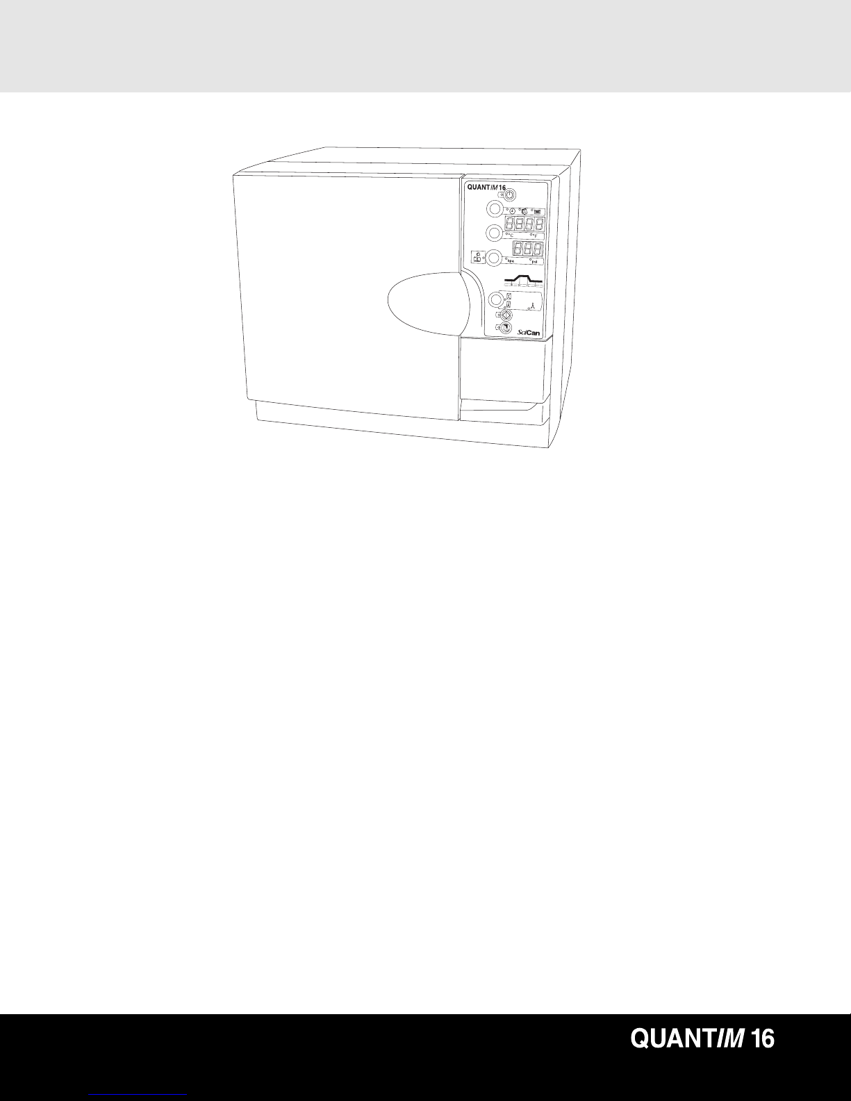
Congratulations on your selection of the QUANTIM 16™ Autoclave. To ensure years
of safe, trouble-free service, carefully review this Operator’s Manual before operating
the unit. By following these simple step-by-step instructions you can ensure your
instruments are correctly sterilized every time. The Quantim 16 is suitable only for the
applications listed in this user manual; use for other purposes may be unsafe.
Operational, maintenance, and replacement instructions must be followed for the
product to perform as designed.The manufacturer cannot be held responsible for
damage caused by improper use.
While unpacking, check the unit for damage that may have been sustained in transit.
If damage is found, please report this to the shipping agent immediately, in writing,
and then notify your dealer.
All trademarks referred to in this manual are the property of their respective owners.
Contents of this manual are subject to change without notice to reflect changes and
improvements to the Quantim 16 product.
Page 4

2.1 Warnings
Do not permit any person other than authorized personnel to supply parts for, service,
or maintain your Quantim 16. SciCan shall not be liable for incidental, special or
consequential damages caused by any maintenance or services performed on the
Quantim 16 by unauthorized personnel, or for the use of equipment or parts
manufactured by a third party, including lost profits, any commercial loss, economic
loss, or loss arising from personal injury.
Never remove the cover of the unit and never insert objects through holes or openings
in the cabinetry. Doing so may damage the unit and / or pose a hazard to the operator.
Pay close attention to the symbols that appear in the margins.
The following symbols indicate:
a potential hazard to the operator
a situation, or circumstance, which may lead to mechanical failure
important information
Page 3
2. Important Information
SciCan
1440 Don Mills Road,
To r onto, ON M3B 3P9
CANADA
Phone: (416) 445-1600
Fax: (416) 445-2727
Toll free: 1-800-667-7733
SciCan Inc.
500 Business Center Drive
Pittsburgh, PA 15205
USA
Phone: (412) 494-0181
Fax: (412) 494-4794
Toll free: 1-800-572-1211
www.scican.com
Email: customer_servicecanada@scican.com
Page 5
Page 4
2. Important Information
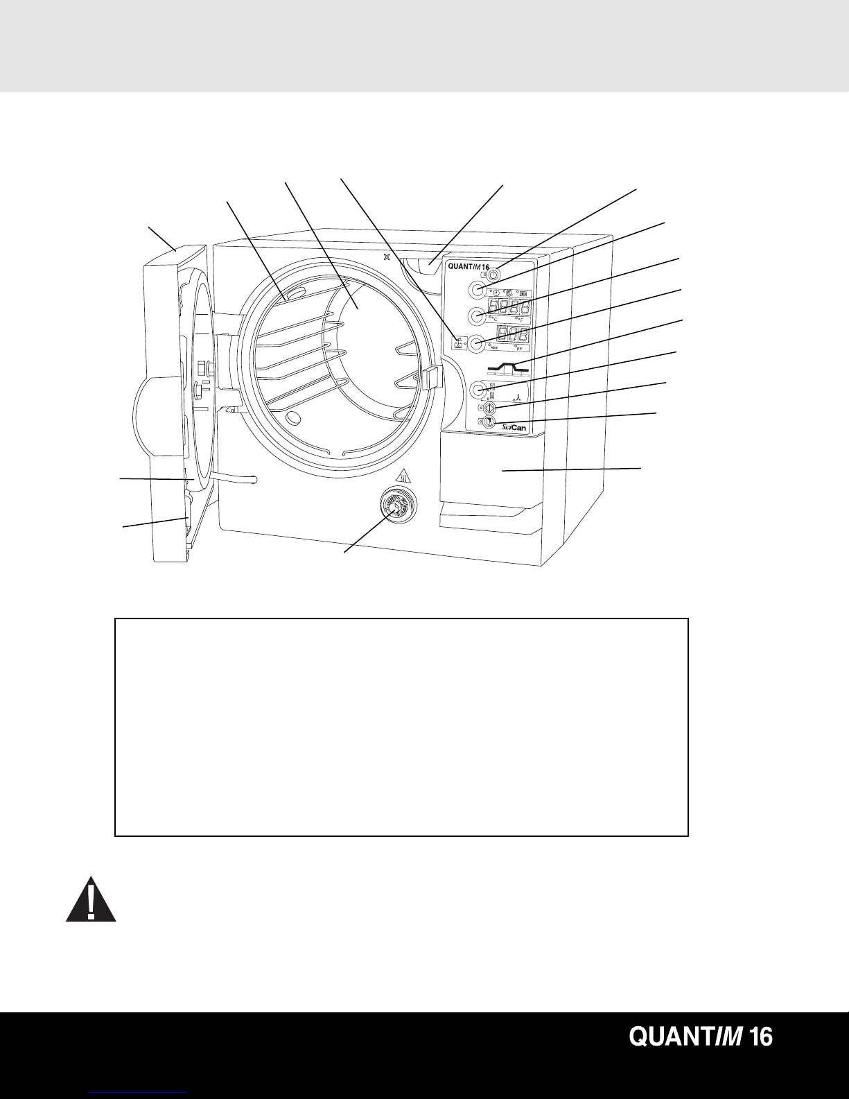
2.2 Item Identification
■
9
■
11
■
16
■
17
■
14
■
13
■
15
■
10
■
1
■
4
■
5
■
6
■
8
■
7
■
2
■
3
■
12
■
1
standby / ready button
■
2
cycle start button
■
3
door open button
■
4
time / date / cycle button
■
5
temperature reading button & display
■
6
pressure reading button & display
■
7
cycle select button
■
8
status indicator
■
9
main autoclave door
■
10
water fill spout
■
11
water tank drain
■
12
printer door
■
13
autoclave chamber
■
14
furniture rack
■
15
low water indicator
■
16
door gasket seal
■
17
air filter
The diagram numbers refer to the following:
The Quantim 16 autoclave is approx. 42 kg or 92 lbs.
At least two people will be needed to lift it.
Page 6

3.1 Installing the Unit
To i n stall the unit, follow these steps:
1. Ensure the unit is placed on a flat, level surface prior to running a sterilization cycle.
To verify if the unit is level, pour half a cup of de-ionized / distilled water into the
chamber. The water should flow towards the rear of the chamber, not out of the front.
The autoclave must be positioned so that the rear is not accessible to personnel and is
not directly in front of an electrical outlet in the event of the overpressure release valve
operating. The autoclave cooling fan outlet is placed at least 100 mm / 4" from any
near by surface.
2. Plug the unit into a 120 V/ 60 Hz - outlet (To check power of the correct power rating,
refer to the rating plate located inside the printer door). After a few seconds, the LED
next to the Standby / Ready button ■
1
will illuminate.
3. The power outlet must be properly grounded. The power plug should also be
easily accessible.
4. Press button
■
1
to set the autoclave in ready mode. The LED next to button ■1will
go out.
3.2 Filling the Tank
Yo u w i ll now need to fill the water tank. To do so, follow these steps:
1. Press button
■
3
to open the door.
2. Remove packing material from inside of chamber.
3. Pour water into the fill spout ■
10
to the maximum line located within fill spout. The tank
requires 3.9 L / 1.03 gal of water.
4. When the low water indicator
■
15
illuminates, the water tank will need to be filled.
Never use tap water. Always use de-ionized or distilled water.
Yo u will now need to set the date and time. The date and time are set in the following
sequence: year (tens); year (hundreds); month; day; minutes; hours.
Page 5
3. Installation
Page 7

Page 6
3. Installation
3.3 Setting the Date and Time
To set the calendar and clock, follow these steps:
1. Ensure the autoclave is in the ready mode by pressing the Standby / Ready button
■
1
. The LED next to button ■1will be out.
2. Press and hold the time / date / cycle button
■
4
for 5 seconds.
3. Set the year (tens) by pressing the time / date / cycle button
■
4
upwards
and the temperature reading button ■5downward.
4. Press the select pressure reading button
■
6
to accept.
5. Set the year (hundreds); month; day; minutes; and hours; by pressing the time /
date / cycle button
■
4
upwards and the Temperature Reading button ■5downward
and Pressure Reading button ■6to accept.
6. The unit returns to the ready mode when the hours have been accepted.
A 24 hr clock is used.
3.4 Single use water system
To install the system the container lid and condensing coil, which are already attached
to the autoclave, need to be fitted by carefully inserting the coil into the container and
fastening the lid by hand.
Fill the waste bottle with tap water up to the “Min” level. The container should be
placed on an even, level surface close to, and preferably below, the autoclave unit.
Page 8
Page 7
4. Indicators and Controls
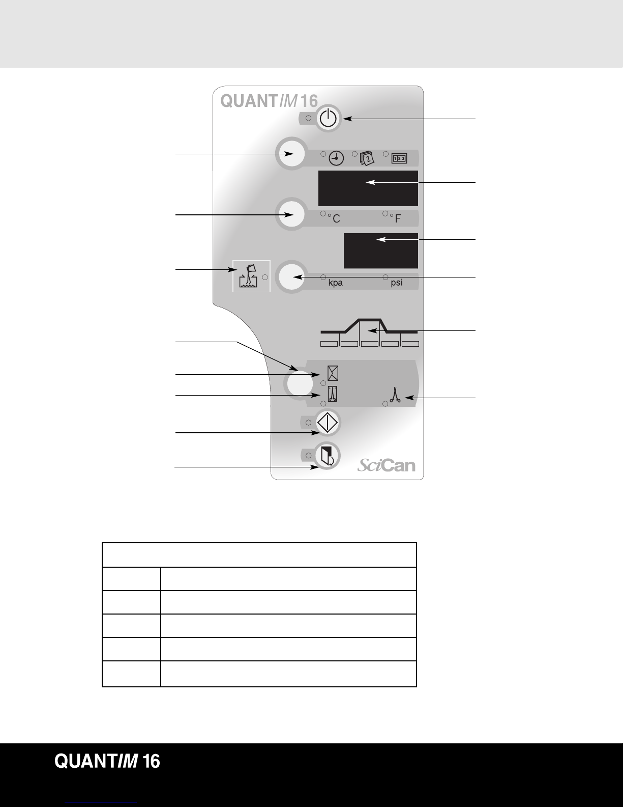
■
4
time / date / cycle counter
■
5
Celsius / Fahrenheit
water fill indicator ■
15
■
7
cycle select button
packs cycle
wrapped cycle
■
2
cycle start button
■
3
door open button
Standby / Ready
■
1
time / temp / date /
counter LED■
17
pressure LED■
18
■
6
pressure reading
button (kpa / psi)
cycle status indicator
■
8
(see below)
unwrapped cycle
A BCDE
A visual cycle indicator ■8 shows the stages of the cycle:
Stage A. Cycle start / water fill ■
A
Stage B. Heating and air bleed ■
B
Stage C. Sterilizing ■
C
Stage D. Depressurization / drying ■
D
Stage E. Cycle complete ■Ethe buzzer sounds 3 times.
Page 9

Page 8
5. Running a Cycle
Cycle Symbol
Unwrapped
instruments
Packs
Te mp./
exposure time
Instruments
Comments
132˚C/ 270˚F /3 min
132˚C/ 270˚F /15 min 121˚C/ 250˚F / 30 min
•For unwrapped
solid
instruments,
hinged
instruments,
dental
handpieces.
•Items which
manufacturers
recomend for
the exposure
at this time
and temperature.
•Solid and hinged
instruments;
dental
handpieces;
loosely wrapped
or individual
instruments
•Wrapped trays
of loose
instruments.
•Items which
manufacturers
recomend for
the exposure
at this time
and temperature.
•Wrapped
surgical packs
•Items which
manufacturers
recomend for
the exposure
at this time
and temperature.
Wrapped
instruments
The sterility
of unwrapped
items can be
compromised
on exposure to
a non-sterile
environment
Not For Liquids
Note: If in doubt regarding an instrument’s suitability for steam sterilization contact
the manufacturer of the instrument directly.
Maximum load is 2 kg / 4.4 lbs
Maximum tray load is:
• 1 kg / 2.2 lbs for wrapped / pouched loads.
• 2 kg / 4.4 lbs for unwrapped loads.
5.1 Cycle Description Chart
Page 10

5.2 Important Points to Remember
•Instruments should always be clean and free of debris and bioburden
prior to sterilization.
• It is recommended that a chemical indicator strip be used with every cycle.
If the chemical indicator strip fails to change after cycle, repeat cycle with
new strip. If this occurs again then arrange for service and do not use autoclave.
•Only use qualified personnel to service this product.
5.3 Running a Cycle
To r u n on e of the three cycles, follow these steps:
1. Disinfectant or hard water residues and solid debris may inhibit the
sterilization and / or performance of the instrument. Clean the instruments
prior to sterilization.
2. Arrange the instruments on the tray so that they do not touch each other.
This ensures that steam reaches all surfaces and will promote drying.
3. Adequate clearance must be provided to ensure that the top of the load does not
strike the tray above nor the chamber ceiling.
4. Close the door by pushing until a ‘click’ is heard. The LED next to the door open
button
■
3
will light.
5. Press the cycle select button ■7until the required cycle is selected. The unit
returns to the default after each cycle. (The default cycle is 132˚C / 269.6˚F.)
6. Press cycle start button ■
2
to start a fully automatic cycle.
At the end of a cycle the buzzer sounds 3 times. The door may now be opened.
Press button
■
3
to open the door.
At the completion of each sterilization cycle the Quantim 16 automatically begins a
vacuum drying cycle.
When the autoclave is drying the load the door may be opened at anytime by pressing
button ■
3
. The cycle will terminate and the door will be ready to open when it is safe.
Page 9
5. Running a Cycle
Page 11

Page 10
5. Running a Cycle
Always use the lifter handle, part #279007 when removing standard open trays from the
autoclave as the instruments may be hot. When using other trays or cassettes, use heat
protective gloves.
If the Drying Phase is interrupted UM 15 will displayed in the pressure display
■
17
.
This can be reset by pressing the Standby / Ready button ■1twice.
Note: It is recommecded that the Drying phase complete its cycle to ensure that the
load is fully dried. When wet instruments, packs and pouches are exposed to an
unsterile environment the sterility of the instruments could be compromised.
If the unit is used in a very cold environment, water vapor may be seen coming from the
cooling fan. This is normal and will only last for a few minutes.
The time is the default on the time / date / cycle display. Once the cycle has completed,
the unit display returns to the default after each cycle. Press button
■
4
to display the date
or number of cycles.
5.4 Aborting a cycle
• Press the standby button in Figure 1.
• This results in the pressure display flashing “Abt”
(Figure 2).
• If the standby button is not pressed again within a
ten second period the display reverts back to
normal and the cycle continues.
Figure 1
Figure 2
Page 12

• If during this ten-second period the standby button is
pressed again the display reverts to either Ready Mode
(Temperature < 95˚C) or recovery (for example does not
allow entry into the unit until the display shows 95˚C).
The display will be as shown in Figure 3.
• When the temperature reaches 95˚C, the fifth
cycle status led will come on and the door led will
be illuminated (Figure 4).
• Press the door button and the unit returns to
Ready Mode.
• On the next cycle the vacuum pump will not run
prior to water fill.
5.5 Types of trays and loading
When loading the unit, the following information should
be observed for the load to be correctly processed:
The furniture rack holds three standard trays and will accomodate other cassettes such
as SysTM cassettes and specific HU-Friedy cassettes. The maximum load for the unit
is 2 kg / 4.4 lbs (1 kg / 2.2 lbs for wrapped loads and 2 kg / 4.4 lbs for unwrapped loads).
The instrument manufacturer's reprocessing instructions should be consulted about
autoclaving suitability. Specifically, the information regarding the maximum
temperature and pressure the instruments can withstand is very important to ensure
instrument damage is avoided.
When placing instruments on the trays, ensure they are placed on the tray ribs to
promote drainage. The height of the load should not interfere with the other trays or the
surrounding chamber. Also, the trays should not touch each other. Always use the lifter
handle, part #279007 when removing the trays from the autoclave as they may be hot.
Long trays should be supported at their rear as they become free of the tray carriers.
Do not touch hot trays with an unprotected hand.
Page 11
5. Running a Cycle
Figure 3
Figure 4
Page 13

Page 12
6. Printer Installation
PULL
View 1 – Front
■
1
power ON light
■
2
printer mechanism open tab
■
3
paper feed button
■
4
cassette ribbon winder
■
5
cassette ribbon "pull" location
■
10
ribbon cassette
View 2 – Rear
■
2
printer mechanism open tab
■
6
printer cable connector socket location
■
7
fixing and screw
View 3 – Front
■
2
printer mechanism open tab
■
7
fixing cam and screw
■
8
printer mechanism swung open
View 4 – Side
■
7
fixing cam and screw
■
8
printer mechanism swung open
View 5 Side – (Printer mechanism
swung open)
■
9
paper roll location and paper fed
into printer mechanism
View 6 – Ribbon cassette
(cassette out of printer)
■
5
cassette ribbon "pull" location
■
10
ribbon cassette
■
12
ribbon
■
11
paper fed through gap
View 7 – Printer door
■
13
paper guide decal location
■
1
■
3
■
2
■
10
■
4
■
5
■
6
■
2
■
7
■
7
■
8
■
2
■
9
■
8
■
5
■
10
■
12
■
11
■
13
■
7
View 1 – Front
View 2 – Rear
View 3 – Front
View 4 – Side
View 5 – Side
(Printer
mechanism
swung open)
View 6 – Ribbon cassette
(cassette out of printer)
View 7 – Printer door
PULL
Page 14

Page 13
6. Printer Installation
6.1 Printer Installation
Install the printer by following these instructions and by referring to the illustrations.
A large flat blade screwdriver will be required.
Disconnect the autoclave from the power supply and wait at least 1 minute
before fitting or removing the printer. Failure to do so may result in permanent damage.
Never pull the paper through the printer mechanism; always use the feed button.
In the event of a paper jam, printing will automatically cease. Reset the printer by
turning the autoclave OFF and then ON again. Check that the paper feed is free
from obstruction.
To i n stall the printer, follow these steps:
1. Open the printer door on the front of the autoclave
2. Locate the printer connector cable with the plug inside the autoclave printer
opening. Free it from the clip and remove the clip from the moulding.
3. Connect the cable to the rear of the printer.
4. To fix the printer:
A) Open the printer and swing the printer mechanism down.
B) Insert the printer into the autoclave printer space. Ensure the printer cable
is to the left of the plastic locating strut, and push home.
C) Using a screwdriver, turn the cam fixing screw anti-clockwise until the the printer
moves in fully. (Do not use excessive force).
D) To fix securely, turn the cam screw a further quarter to one turn anti-clockwise.
E) Reconnect the autoclave to the power supply.
Page 15

Page 14
6. Printer Installation
6.2 Installing Paper into the Printer
Install the paper roll by following these steps and by referring to the illustrations.
1. Open the printer door. Open the printer
■
2
and swing the printer mechanism down.
2. Note the position the printer paper feeds into the printer mechanism
■
9
.
3. Ensure the printer mechanism is clear of old paper by pressing the feed button.
Do not pull the paper backwards out of the mechanism.
4. Reel off a few centimeters of paper from the new roll; ensure that the paper end
is squarely cut.
5. Place the new paper roll into the printer casing with the paper end coming from the
bottom of the roll ■
9
.
6. Offer paper into the back of the printer mechanism ■9. Press feed button ■3.
7. Press the feed button
■
3
until 50 mm of paper is fed through the paper exit slot.
8. Swing printer mechanism up and close. Press the feed button to feed a further
10mm of paper out.
9. Close the external printer door. Ensure the paper is protruding out from the
base of the external door and is not obstructed.
6.3 Ribbon Installation
1. Open the printer door
2. Remove the old ribbon cassette by pulling on the area marked “pull”
■
5
.
The cassette will unclip on one side and can then be removed.
3. Check that the ribbon on the new cassette is taut. Wind the knob ■4in the
direction shown on the cassette to take up any slack.
4. Feed the printer paper through the gap
■
11
between the ribbon ■12and
the cassette ■10.
5. Clip the new ribbon cassette into place in the reverse sequence for removal.
6. Wind the knob
■
4
a few turns in the direction shown on the cassette to take up
slack in the ribbon.
7. Close the external printer door. Ensure the paper is protruding out from the base
of the external door and is not obstructed.
Page 16

Page 15
7. Accessories
Product - Part number
Printer – 289083
Printer Ribbon – 279221
Paper Roll - 279001
Stainless Steel Pouch Rack (282 mm / 11") – 279009
6 tray chamber rack – 279229
Stainless Steel Tray (282 mm / 11") – 279006
Stainless Steel Lifter Handle – 279007
Printer – 289083
Stainless Steel Pouch Rack (282 mm / 11") – 279009
6 tray chamber rack – 279229
Stainless Steel Tray (282 mm / 11") – 279006
Stainless Steel Lifter Handle – 279007
Page 17

Page 16
8. Maintenance
8.1 Door Seal Gasket
The door seal gasket ■16must be cleaned on a daily basis before using the autoclave.
Wipe the exposed surface of the gasket and the sealing surface of the vessel with warm
soapy water using a damp lint free cloth. Wipe / rinse the gasket and vessel again with
plain water to remove any residual soap. Repeat as needed.
Inspect the gasket frequently for the presence of any leaks. If a leak is noted, the gasket
should be removed and cleaned thoroughly in warm soapy water rinsed, and then
shaken dry. Do not wipe dry. The door plate must also be cleaned at that time.
If the leak persists during a follow-up test cycle then a new seal should be obtained
and the defective seal replaced.
To r em o ve the gasket, follow these steps:
1. Undo the dome nut(s) and remove both nut(s) and ‘O’ ring seals. Always replace
the “O” ring seal(s) before reassembly.
2. Remove the plate /gasket assembly, and gasket from the plate.
3. During re-assembly, place the “O” ring seal(s) under the head(s) of the dome nut(s).
Do not overtighten as this may damage the thread. Ensure that the entry port plugs
align with the holes in the cast lid.
8.2 Fresh water tank
The manufacturer recommends the weekly full draining of the unit to minimize any
potential for biofilm formation.
A drain fitting and tubing are provided to drain the reservoir. Detach the tubing from the
retainer clip on the inside of the door and place the open end of the drain tubing into a
container. Open the valve on the end of the tubing and fully drain reservoir. When
empty, close the tubing valve and re-set tubing in retainer clip.
Refill the reservoir with clean distilled water.
8.3 Routine maintenance
Routine annual maintenance including such tasks as filter replacements are required
for this unit. Contact your authorized dealer or your SciCan technician to book your
service appointment.
Page 18

Page 17
8. Maintenance
8.4 Waste bottle
The waste bottle has to be regularly checked and be emptied when the water reaches
the “Max” level. One easy way to remember is to empty the waste bottle every time
you fill up the water reservoir. After emptying the waste bottle fill it up to “Min” level
with tap water.
8.5 Biological air filter
For closed door drying of instruments (in sterile environment) the air enters the
sterilization chamber via the biological air filter. Check the filter regularly and replace
it when dirty. Air filter replacement is recommended every 500 cycle or 6 months
whichever comes first. Just pull the filter out and disconnect the tubing. Install the
new filter and put it back in place.
Page 19

Page 18
9. Troubleshooting
If the software detects any unusual condition, a visual and audible indication will be
given. The nature of the condition can be determined by reference to the fault guide.
The recovery sequence allows access to any instruments within the autoclave.
Low water LED ■
15
Insufficient water in the
tank to run a cycle.
Condition indicated Cause Remedy
1. Press button ■1twice.
2. Open the door and top up with water.
‘DOOR’ illuminates
on display
■
17
Cycle start button ■
2
pressed while door is open.
1. Close the door and try again.
01
Power failure during cycle. 1. Recovery sequence ‘i’.
2. Check the power supply.
02 (b/d/t)
Annex A failure (time or
temperature).
1. Recovery sequence ‘i’.
2. Clean the gasket and chamber
face (b/d E02).
2ii. Check and reset the clock (tE02).
03
Air bleed has not been
successful.
1. Recovery sequence ‘i’.
2. Clean the gasket and chamber face.
07
Sensor fault - Thermistor. 1. Recovery sequence ‘ii’.
2. Engineer call-out required.
10
Water in boiler. 1. Recovery sequence ‘iii’.
2. Run a cycle.
12
Boiled dry. 1. Recovery sequence ‘i’.
2. Ensure the autoclave is on a flat,
level surface.
3. Clean the door gasket and
chamber face.
13
Boiler failed to fill
with water.
1. Recovery sequence ‘i’.
2. Drain the water from the autoclave
and refill with distilled/de-ionized water.
14
Sensor fault PT100 Chamber.
1. Recovery sequence ‘ii’.
2. Engineer call-out required.
15
Door opened during drying. 1. Recovery sequence ‘i’.
17
Failure to dump all steam
from chamber after
sterilizing.
1. Press Stand-by button 1 for recovery
sequence.
2. Check external dump pipe for restrictions.
3. If pipe OK engineer call-out required.
18
Minor leak detected from
vessel.
1. Press Stand-by button 1 for recovery
sequence.
2. Engineer call-out required.
Page 20

Recovery Sequence (allows instruments to be removed from the unit)
•Recovery Sequence ‘i’: Press
■
1
–‘Stabilize’ (no ‘flashing’, no ‘beeping’)
Press ■1– ‘Recover’
•Recovery Sequence ‘ii’ Press
■
1
–‘Stabilize’ (no ‘flashing’, no ‘beeping’)
Cannot proceed (door not enabled). Contact your local dealer or service technician.
•Recovery Sequence ‘iii’ Press ■
1
–‘Stabilize’ (no ‘flashing’, no ‘beeping’) Press ■
1
to enter ‘Ready’ state
The recovery sequence will allow the selected sterilizing cycle to be completed before
the boiler flushes and any remaining air is bled from the chamber. Once this sequence
has been completed the unit holds for 60 seconds or, until the internal temperature
falls to 88˚C / 190.4˚F before the door can be opened and a continuous beeping
alert sounds.
Before restarting a cycle, check that the plug is fully inserted into the power outlet socket
and the outlet is grounded. If all power is lost, the door cannot be opened until power
is restored.
Should an internal power failure occur, the door cannot be opened. (Contact you dealer
for advice) Should it be clear that an indicating device is suspect, a service will be
required to correct the condition.
Should a safety feature operate, unplug the unit and call for a service - do not attempt to
correct the condition.
Primary safety features:
Tw o p r i mary safety features have been fitted – a pressure release valve and a boiler over
temperature safety cutout.
Page 19
9. Troubleshooting
Page 21

Page 20
10. Warranty
Limited Warranty
For a period of one year*, SciCan guarantees that the QUANTIM 16, when supplied by
SciCan in new and unused condition, will not fail during normal service due to defects
in material and workmanship that are not due to apparent abuse, misuse, or accident.
* For all units sold in the United States, this period is extended to two years.
In the event of failure due to such defects during this period of time, the exclusive
remedies shall be repair or replacement, at SciCan’s option and without charge, of any
defective part(s) (except gasket), provided SciCan is notified in writing within thirty(30)
days of the date of such a failure and further provided that the defective part(s) are
returned to SciCan prepaid.
This warranty shall be considered to be valid, if the product is accompanied by the
original purchase invoice from the authorized SciCan dealer, and such invoice identifies
the item by serial number and clearly states the date of purchase. No other validation is
acceptable. After one year, all SciCan’s warranties and other duties with respect to the
quality of the product shall be conclusively presumed to have been satisfied, all liability
therefore shall terminate, and no action or breach of any such warranty or duty may
thereafter be commenced against SciCan.
Any express warranty not provided hereon and any implied warranty or representation
as to performance, and any remedy for breach of contract which, but for this provision,
might arise by implication, operation of law, custom of trade or course of dealing ,
including any implied warranty of merchantability or of fitness for particular purpose with
respect to all and any products supplied by SciCan is excluded and disclaimed by
SciCan. If you would like to learn more about SciCan products and features, visit our
website at www.scican.com.
Page 22

Chamber Capacities: 16 L / 4.23 ga
Overall product width: 480 mm / 18.9"
Overall product height: 410 mm / 16.14"
Overall product length: 440 mm / 17.3"
Unpacked weight: 41kg (max) / 90.4lbs
Chamber diameter: 250 mm / 9.9"
Chamber lengths: 330 mm / 13"
Tr ay capacity/length: 3@282 mm / 11.1"
Max instrument length: 282 mm/11.1"
Max instrument load: 2 kg / 4.4 lbs
Sterilizing temperature / time: Unwrapped –132˚C / 3 minutes or 269.9˚F / 3 minutes
Wrapped –132˚C / 15 minutes or 269.9˚F / 15 minutes
Packs / Liquids –121˚C / 30 minutes or 249.8˚F /
30 minutes
Cycles: 4
Operating pressure (minimum): 1.05/2.05bar or 15.23/29.72psi
Voltage / wattage / frequency: 120 v / 1500 w / 60 Hz
The overall cycle time will increase as the mains supply voltage decreases.
Chamber component materials:
Vessel: Stainless steel – 304 – S15
Boiler: Aluminum – LM25
Lid: Aluminum – ANSI 356 –0
Fuses: Fuses are located under the cable access panel
■
8
on the rear of the unit.
Disconnect the autoclave from the mains power supply before changing fuses.
Only qualified personnel should replace fuses.
Fuse Type: Only fit slow blow fuses (MDA 15A) or equivalent.
32 x 6,3 mm (1,25 x 0,25 in)
Page 21
11. Specifications
Page 23

Page 22
11. Specifications
Rating: All products are rated for intermittent
use, continuously
Heater: Cast into boiler
Te mperature cutout: Bimetallic type with manual only reset.
This operates at 170˚C / 338˚F
Pressure release valve: Operates at 2.76 bar or 40psi.
Manufactured to ASME code and UV stamped. Accumulation is ≤ 10%
Over-voltage category: Group II
Pollution degree: Group 2
Insulation: Class 1
Environmental conditions: Indoor use at an altitude of up to 2,000 m / 6561.7 ft.
Ambient temperature range + 10˚C / 50˚F to + 40˚C/104˚F Maximum relative humidity
80 % for temperatures up to 31˚C / 87.8˚F, decreasing linearly to 50 % at 40˚C / 104˚F.
Power supply voltage range 99 to 132 volts (120 v)
Page 24

Declaration of Compliance – SciCan Corporation
This hereby certifies that the design, construction and testing of the vessel complies with
ASME VIII.
Sterilizer Type: Tr ansportable AUTOCLAVE
Vessel Description: Boiler / Receiver – Electrically heated, self generating autoclave.
Approximate internal dimensions – 320 x 247 mm
Manufacture: Ye ar of Manufacturer – see serial number on back of unit
Manufacturer – BI Group
Design Organization – BI Group
Inspecting Authority Approving Design – Royal & Sun-Alliance
Reference of Inspecting Authority Approval: SS983212 / 1 / CET
Inspecting Authority Verifying QC System – BSI
Design Pressure (Max) – 2.76 Bar
Design Temperature (Max) – 141.0˚C
Post-Weld heat treatment is not applicable
Hydrostatic Pressure Test:
Location: Assembly Area
Te st Pressure: 4.6 Bar
Te st Medium & temp: water – 20˚C Typical
SciCan, A Division of Lux & Zwingenberger,
1440 Don Mills Rd., Toronto, ON, M3B3P9
Te l: (416) 446-2706, Fax: (416) 445-2727.
Page 23
12. Pressure Vessel Certificate of Compliance
 Loading...