

Page 1
SD-438 EU EN R5
1
SciCan Ltd. 1440 Don Mills Road, Toronto, Ontario, Canada. M3B 3P9
HYDRIM G4 Washer-Disinfector
Pre-Installation Instructions
To ensure the optimum performance of SciCan’s washer-disinfector models it is imperative that the
correct services are made available and that the positioning of the unit does not compromise the
function of the unit in any way.
Prior to installation it is important that the site be inspected and all the appropriate conditions are met
to ensure the safe and efficient operation of the washer-disinfector.
Practice details and summary results.
Practice/Office location details
Customer Name:
Address:
Tel:
Signature:
Installer/Pre-installation inspector
Name:
Dealer details:
Tel:
Conditions approved/rejected for installation subject to checklist below (!/" )
Name:
Signature:
Date:
On behalf of (Dealer):
Page 2
SD-438 EU EN R5
2
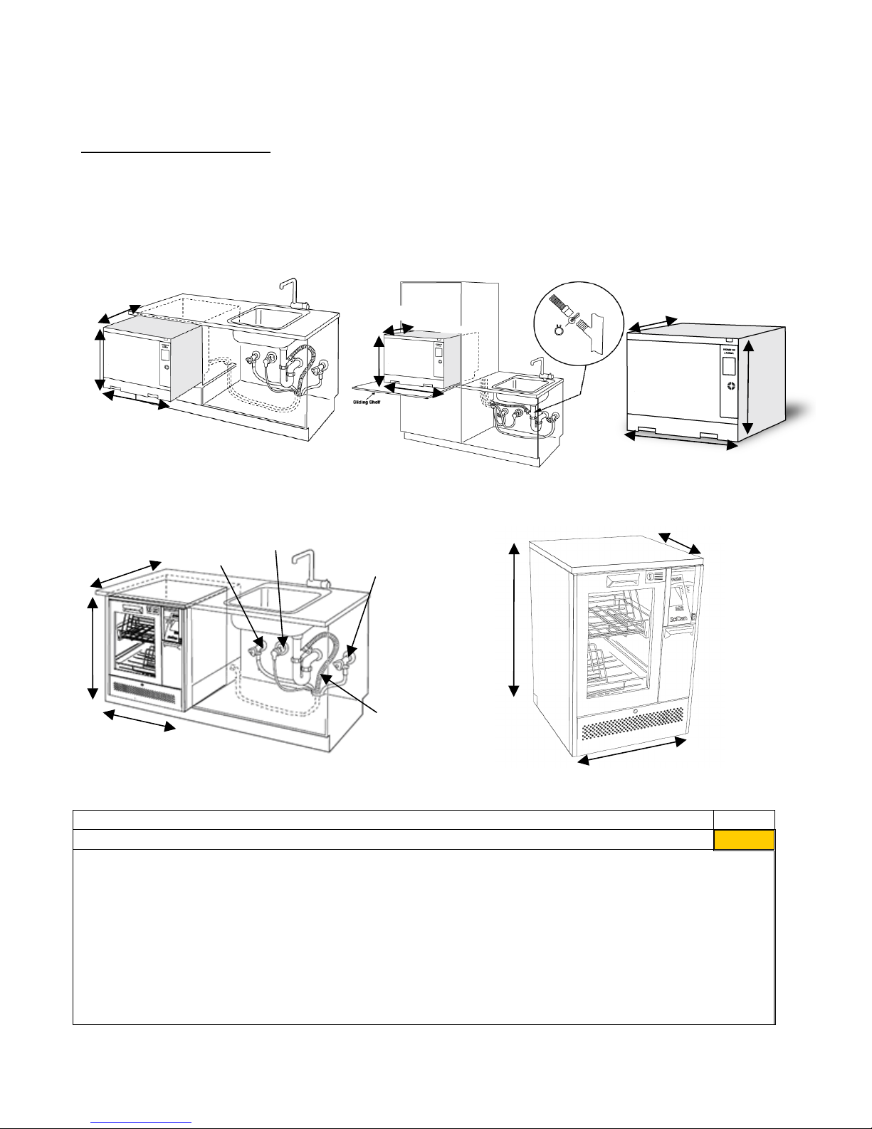
Installation Configuration
The washer-disinfector may be installed under-bench or free standing dependent on space and
service availability. Please select appropriate model number for the installation configuration.
The HYDRIM C61wd G4 configuration options are:
NOTE: LCS Models must also have a compressed air supply within 2 m of installation site
Option 1: Cabinet/ Sterilization Center Option 2: Sliding Shelf Option 3: Counter Top
The HYDRIM M2 G4 configuration options are:
Option 1: Cabinet/ Sterilization Center (M2 G4 Short model) Option 2: Free Standing (M2 G4 Standard model)
Space Requirements
!/"
• Ensure adequate space is available to install the unit
Note 1: Although not required, if the HYDRIM is installed under a counter, it is recommended to allow at least
10 mm space at the top and both sides of the unit. This will facilitate installation levelling, and service access
to the HYDRIM.
Note 2: Avoid installing the HYDRIM in direct sunlight.
Note 3: Important! Ventilation during drying is via the front of the machine. Some increase in humidity may
be apparent during this drying phase and it is imperative that sufficient air circulation is available surrounding
the machine to enable this humidity to be dissipated. Failure to provide adequate ventilation may lead to
equipment or cabinetry damage (depending on installation configuration).
Note 4: The drying system has a filtered air intake at the front of the unit. The free movement of air to this
Power connection
Hot Water
connection
Cold Water
connection
Drain
connection
598 mm + 10mm
820 mm
598 mm + 20mm
850 mm
598mm
598mm
520mm + 10mm
598mm + 20mm
526mm
520mm
+ 10mm
598mm + 20mm
526mm
520mm
598mm
526 mm
Page 3

SD-438 EU EN R5
3
intake is important and failure to provide the required space may cause overheating of the dryer motor
and/or compromise drying efficiency.
Note 5: The unit should be installed as supplied as every part of the unit has a purpose to guarantee trouble
free operation. In particular, the legs of the HYDRIM G4 have been designed to distribute the weight of the
machine to the chassis of the unit and to ensure a leveled installation. If units are installed without legs, the unit
may start to leak from the door. Therefore, the legs of the unit cannot be removed for installation
purposes.
Pre Installation Checklist
The following items are required to be in place before installation begins.
Description
!/"
Hot water/Cold water/Reverse Osmosis (RO) water feed with G ¾” or DN 20 shut off
valve (washing machine fitting)
Distance of water connections
• Maximum distance from installation less than 1.50 m / 5 ft
Water inlet pressure
• HYDRIM C61wd G4: 1 to 10 bar / 14 to 145 psi
• HYDRIM M2 G4: 2 to 5 bar / 29 to 72 psi
Minimum water supply for each inlet
• HYDRIM C61wd G4: 2.5 L/min
• HYDRIM M2 G4: 4.5 L/min
Note 1: If hot water is not available then it must be possible to attach a ‘Y’ fitting to the cold water feed valve
so that both machine pipes can be connected to the cold supply. The machine will not work with only one
supply attached as it requires pressure in both supplies to activate the feed pressure switches. Please note
that cold fill only will increase cycle times.
Note 2: Water feeds should be adjacent to the machine and not behind it so that the shut off valves may be
accessed in case emergency isolation is required and to ensure unit can be inserted fully under the work
surface.
Drain outlet
!/"
• Maximum distance from installation is 1.50 m / 5 ft with supplied drain hose
• The maximum length of an extended drain hose should not exceed 3.30 m / 10.8
ft.
• Drain should be no more than 1 m / 3.2 ft above the base of the HYDRIM unit.
• ‘P’ trap spur connection (preferred method) OR standpipe connection
• Accommodate ¾” drain hose
• Material of drain must withstand 95°C fluid
Note 1: The preferred method of connection of the HYDRIM to the drain is by the use of a ‘spurred’ ‘P’ trap
fitting.
Note 2: The waste connection pipe is clamped on to the spur by the clips provided with the HYDRIM.
Wherever possible, if the HYDRIM is located close to a sink unit, then this method should be used. If the
HYDRIM is not close to a sink unit and a ‘P’ trap cannot be used, then a standpipe with ‘U’ bend fitting can
be used. This must be a dedicated standpipe. Under no circumstances should any other equipment
Page 4

SD-438 EU EN R5
4
share the standpipe.
Note 3: Waste connection should be adjacent to the machine and not behind it.
General Notes
Note 1: Washer-disinfectors, by their very nature, use water and chemicals and also generate heat. It is
important therefore that their surroundings (cabinetry and flooring) are of good quality and in good condition
to minimise the risk of damage, particularly where a ‘built in’ configuration is used.
Note 2: The HYDRIM G4 is also heavy! Consideration should therefore be given to the structural integrity of
the flooring (see “Technical Specifications Summary”)
Note 3: It is also important that the flooring is flat, and does not run out greater than 2mm front to back and
side to side over the footprint of the unit (see “Technical Specifications Summary”)
Note 4: From time to time, access will be required to change the air filter and/or service the machine. It is
important therefore to ensure that adequate space is available in front of the machine to allow easy removal
of the equipment. Ensure that when the machine is pulled out that the integrity of the services is not
compromised.
Optimum features should be as follows:
• Cabinetry/floor
!/"
o Waterproof
o Sealed edges
o Heat resistance
o Sound structural integrity
o Post installation access
o Flatness (See note 3 above)
Water Quality
The quality of the water being used in the HYDRIM to clean the medical instruments is very critical to
achieving satisfying cleaning results and to protecting the instruments and the internal parts of the HYDRIM
from deterioration. Dissolved solids in the water can cause stains, spots, and corrosion on instruments and
the internal parts of the HYDRIM.
Before installing and using the HYDRIM, SciCan recommends testing the water and recording the results for
future references here.
The following table lists the desired levels of the water parameters:
If the water hardness exceeds 250 mg/L, then external water softener may be required as the built-in water
softener may not be as effective at that level of water hardness.
In addition, if the test results of any of the water parameters exceed the stated problem levels, a full water
analysis is recommended and the installation of a water treatment system may be required.
The following table lists the desired levels of additional water parameters:
Water Parameter
Desired Level
Units*
Problem Level
Alkalinity
75
mg/L
< 40 or > 120
Iron
< 0.05
mg/L
> 0.20
Water Parameter
Desired Level
Units*
Problem Level
pH value
7.0 – 7.5
S.U.
< 6.8 or > 8.5
Hardness
< 85
mg/L
> 100
Total Dissolved Solids (TDS)
< 175
mg/L
> 300
Page 5

SD-438 EU EN R5
5
Manganese
< 0.01
mg/L
> 0.04
Chloride
< 20
mg/L
> 30
*For water, milligram per liter (mg/L) equals parts per million (ppm)
If full water analysis results in parameters exceeding problem level, then a water treatment system
is highly recommended. The HYDRIM washer-disinfectors are fitted with an additional water inlet,
specifically for external water treatment systems (such as deionised or RO).
There may be instances where parameters are below the stated problem levels, however staining
still occurs. A water treatment system may be needed to prevent the staining – see SD-447 Water
Quality Document available on mySciCan for additional information.
The HYDRIM is also equipped with an air gap / anti-suction device to prevent backflow of dirty
water into the water supply.
• Water hardness
o Hot water
o Cold water
• Water conductivity
• pH value
o
Action required (if any):
Internet Connection
!/"
Install a Cat 5 or 6 Ethernet port
Note 1: The port should be installed in a cabinet adjacent to the unit.
Note 2: Ensure that the port has access to the office network and the internet.
Note 3: Although the unit can be connected to a bridge for wireless access, it is recommended to use hard
wired connection to minimize risks with network connections.
Note 4: If the office has purchased (or plans to purchase) other internet connectivity (G4) products, install
multiple Ethernet ports to accommodate other G4 products from SciCan.
HIP/HIP Ultra cleaning solution
!/"
Order Cleaning solution
HYDRIM C61wd G4: HIP Ultra cleaning solution (CS-HIPC-U)
HYDRIM M2 G4: HIP cleaning solution (CS-HIPL) or HIP Enzymatic (CS-HIPL-E)
Note 1: HIP, HIP Ultra or HIP Enzymatic cleaning solution is required to run the machine and is not included
with the machine. Please ensure cleaning solution has been provided prior to installation.
Compressed Air (HYDRIM C61wd G4 LCS Model ONLY)
!/"
Availability of a DN 7.2 connection for compressed air
Air pressure must be between 1 bar (15 PSI) - 10 bar (145 PSI)
Distance between unit installation site and compressed air connection must be within 2 m
Page 6

SD-438 EU EN R5
6
Electrical supply
Refer to model number for specific requirements
Model Number
Ending
Current
(see note 1)
Voltage
Frequency
Maximum power supply
location for installation site
Rated
load
!/"
-D01
12A
208-240 V
60 Hz
1.50 m / 5 ft
2.7 kW
-D06
12A
200-230 V
60 Hz
1.50 m / 5 ft
2.7 kW
-D11
12A
200-230 V
60 Hz
1.50 m / 5 ft
2.7 kW
-D02
12A
200-230 V
50 Hz
1.50 m / 5 ft
2.7 kW
-D04
12A
200-230 V
50 Hz
1.50 m / 5 ft
2.7 kW
-D05
12A
200-230 V
50 Hz
1.50 m / 5 ft
2.7 kW
-D12
12A
200-230 V
50 Hz
1.50 m / 5 ft
2.7 kW
HYDRIM C61wd G4
(including LCS models)
-D13
12A
200-230 V
50 Hz
1.50 m / 5 ft
2.7 kW
-D01
12A
230-240 V
60 Hz
1.50 m / 5 ft
2.5 kW
-D03
13A
230-240 V
60 Hz
1.50 m / 5 ft
2.5 kW
-D02
13A
230-240 V
50 Hz
1.50 m / 5 ft
2.5 kW
-D04
13A
230-240 V
50 Hz
1.50 m / 5 ft
2.5 kW
HYDRIM M2 G4
(including short models)
-D10
13A
230-240 V
50 Hz
1.50 m / 5 ft
2.5 kW
Note 1 - The HYDRIM G4 is supplied with a domestic fused plug as standard. A dedicated hard wired supply can also be used.
Note 2 - Due to the power requirements of the HYDRIM, (see rated load) especially during drying, it is advised that no other equipment is
connected to the same supply outlet.
Note 3 - Power supply outlet should be adjacent to the machine and NOT behind it. The cable should be routed away from the back panel and
hot water inlet hose.
Page 7

SD-438 EU EN R5
7
INSTALLATION OVERVIEW
SUMMARY
!/"
Sufficient space for unit installation
Hot and cold water feeds are installed
Drain pipes are prepared
Electrical requirements are met
Cabinetry/floors can withstand operation of the unit
Water quality is acceptable
Internet connection installed
HIP/HIP Ultra cleaning solution ordered
Compressed air connection (HYDRIM C61wd G4 LCS model ONLY)
Follow-up Comments:
Page 8

SD-438 EU EN R5
8
Technical Specifications Summary
HYDRIM C61wd G4
Applicable Standards
ISO 15883-1/2
Height
520 mm
Width
598 mm
Depth (Door closed)
598 mm
Depth (Door open)
829 mm
Weight
44 kg
Floor loading per support when full
152 N
Required clearance on top and sides
>10mm
Running Noise
65 dB(A)
Inlet water connections
G ¾” or DN 20
Inlet water pressure
1-10 bar
Minimum water supply
HYDRIM C61wd G4: 2.5 L/min
Drain
¾”
Maximum water flow to drain
47 L/min
Maximum water discharge temperature to drain
95°C
Maximum water hardness
30.3°dH, 31.6 US GPG, 540 PPM
Maximum water conductivity
844 µS/cm
pH range
>6.8 and < 8.5
Water volume per process stage
3.8 L ± 0.5 L
P3 has additional 18.9 ± 1L for drying
Total water consumption per cycle with drying
P1 & P2: 11.4 L ± 1.5 L
P3: 30.3 L ± 2.5 L
Maximum heat transmitted through fascia
1200 W
Water softener salt capacity
0.5 kg / 1.1 lbs
Equipment installation category
II
Voltage*
208 – 240 VAC, OR
200 – 230 VAC ± 10%
Frequency*
50 Hz or 60 Hz
Rated load
2.7 kW
Current
12A
Operating temperature range
5°C – 40°C
Maximum relative humidity
80% for temp up to 31°C
50% for temp up to 40°C
Maximum operating altitude
2000 m
Equipment pollution degree
2
Maximum deviation from plane horizontal surface.
2mm
Suitable process chemicals for each stage
HIP Ultra
Total amount of process chemical
43.5 mL
Material Safety Data Sheet
Refer to download page of website
Cycle recording options
USB, G4 web portal, external printer
Air pressure range (LCS Model Only)
1 bar (15 PSI) - 10 bar (145 PSI)
Compressed air connection
DN 7.2
*Refer to Electrical Supply table
Page 9

SD-438 EU EN R5
9
Technical Specifications Summary
HYDRIM M2 G4
Applicable Standards
ISO 15883-1/2
Height (Standard height unit)
850 mm
Height (Short height unit)
820 mm
Width
598 mm
Depth (Door closed)
600 mm
Depth (Door open)
1200 mm
Weight
90 kg
Floor loading per support when full
310 N
Required clearance: Top and Sides
Rear
>10mm
>50mm
Running Noise
<78 dB(A)
Inlet water connections
G 3/4” or DN 20
Inlet water pressure
2-5 bar
Minimum water supply
HYDRIM M2 G4: 4.5 L/min
Drain
3/4”
Maximum water flow to drain
47 L/min
Maximum water discharge temperature to drain
95°C
Maximum water hardness
30.3°dH, 31.6 US GPG, 540 PPM
Maximum water conductivity
844 µS/cm
pH range
>6.8 and < 8.5
Water volume per process stage
8 L ± 1 L
P3 has additional 8 ± 1L for drying
Total water consumption per cycle with drying
P1: 16 L ± 2 L
P2: 32 L ± 4 L
P3: 40 L ± 5 L
Maximum heat transmitted through fascia
2388 W
Water softener salt capacity
1.0 kg
Equipment installation category
II
Voltage
230 – 240 VAC ± 10%
Frequency*
50 Hz or 60 Hz
Rated load
2.5 kW
Current*
12A or 13A
Operating temperature range
5°C – 40°C
Maximum relative humidity
80% for temp up to 31°C
50% for temp up to 40°C
Maximum operating altitude
2000 m
Equipment pollution degree
2
Maximum deviation from plane horizontal surface.
2mm
Suitable process chemicals for each stage
HIP or HIP Enzymatic
Total amount of process chemical
108 mL
Material Safety Data Sheet
Refer to download page of website
Cycle recording options
USB, G4 web portal, external printer
*Refer to Electrical Supply table
 Loading...