

Page 1
HYDRIM C61w G4
INSTRUMENT WASHER
• Service Manual
• Manuel de l’utilisateur
HYDRIM C61w G4 Service Manual 95-113023 Rev. 1.0 Copyright 2013 SciCan Ltd . All rights reserved.
Page 2

Contents
1. Introduction ................................... 4
1.1 Overview .................................................. 4
1.2 Unit at a glance ....................................... 5
With cover and panels removed top ...... 6
With cover and panels removed bottom 7
1.3 Specifications .......................................... 8
1.4 Safety information ................................... 9
Safe operation......................................... 9
Safe servicing ......................................... 9
1.5 Tools and hardware ............................... 10
1.6 Shipping instructions ............................. 11
1.7 Installation ............................................. 11
1.8 Setting water softener ........................... 12
1.9 Setting the language ............................. 13
1.10 Setting the country .............................. 13
1.11 Setting the time ................................... 13
1.12 Setting the date ................................... 14
1.13 Assigning the unit identifier number.... 14
1.14 Resetting the drying counter ............... 14
1.15 Adjusting the screensaver delay ......... 15
1.16 Adjusting temperature display ............ 15
1.17
Turning the button sound ON or OFF ..
1.18 Adjusting the button beep volume ...... 15
1.19 Adjusting the salt regeneration ........... 16
1.20 Adjusting the screen contrast ............. 16
1.21 Changing the touchscreen
display themes .................................... 16
1.22 Creating a user name .......................... 17
1.23 Creating a user PIN ............................. 17
1.24 Setting up process enforced usage .... 18
1.25 Connecting to a network ..................... 18
1.26 Connecting to a wireless network ....... 19
15
2. Routine Procedures
and Maintenance ......................... 20
2.1
Replacing the HIP™ Ultra cleaning solution
2.2 Changing the HEPA filter ...................... 21
2.3 Filter and wash arm maintenance ......... 21
2.4 Cleaning the chamber ........................... 22
2.5
Draining the unit for service or shipping
2.6 Upgrading the firmware ......................... 22
2.7
Using the HYDRIM remote access function
2.8 Annual Service Requirements ............... 24
20
.. 22
.. 23
3. Diagnostics and Troubleshooting .. 26
3.1 Using the service menu ......................... 26
3.2 Using the setup menu ........................... 27
3.3 Using the user menu ............................. 28
3.4 Using software tools for diagnostics..... 29
Debug Screen ........................................ 29
I/O status screen ................................... 30
3.5 Troubleshooting cycle faults ................. 31
4. Removing and Replacing Panels ... 35
4.1
Removing and reinstalling the top panel
4.2
Removing and reinstalling the left panel
4.3
Removing and reinstalling the right panel
4.4
Removing and reinstalling the back panel
4.5 Removing and reinstalling
the bottom panel ................................... 38
.. 36
.. 36
.. 37
.. 37
5. Front Components ......................... 39
5.1
Removing and reinstalling the kickplate
5.2 Removing and reinstalling
the power switch ................................... 41
6. Door Components .......................... 42
6.1 Removing and reinstalling door fascia .. 43
6.2
Removing and reinstalling door springs
6.3 Removing and reinstalling the door ...... 45
6.4 Removing and reinstalling LCD
and LCD controller ................................ 46
6.5 Removing and reinstalling the LCD fan 46
6.6 Removing and reinstalling the speaker 46
6.7 Removing and reinstalling
the door latch assembly ........................ 47
6.8 Removing and replacing
the door microswitch ............................. 47
6.9 Removing and replacing
the door latch solenoid .......................... 47
6.10
Removing and replacing the door seal
6.11 Removing and replacing
the chamber seal ................................. 49
.. 40
.. 44
.. 48
7. Right Side Components ................. 50
7.1 Removing and reinstalling
the DC power source ............................ 51
7.2 Removing and reinstalling
the reservoir filling pump ....................... 52
7.3 Removing and reinstalling
the dosing/bellows pump ...................... 52
7.4 Removing and reinstalling
the dosing reservoir ............................... 53
7.5 Removing and reinstalling
the I/O board ......................................... 53
7.6 Removing and reinstalling
the chemical bracket ............................. 54
7.7 Removing and reinstalling
the pressure switch ............................... 55
8. Left Side Components ................... 56
8.1 Removing and reinstalling
the air gap ............................................. 57
8.2 Removing and reinstalling
the dryer heater ..................................... 59
8.3 Removing and reinstalling
the dryer assembly ................................ 59
2
Page 3

Contents
9. Rear Components .......................... 60
9.1 Removing and replacing
the power source fan ............................ 61
9.2 Removing and reinstalling
the air gap pump ................................... 62
9.3 Removing and reinstalling
the exhaust duct .................................... 63
10. Top Components ........................... 64
10.1 Removing and reinstalling
the USB port ........................................ 65
10.2 Disconnecting and reconnecting
the upper wash arm inlet ..................... 66
10.3 Removing and reinstalling
the upper wash arm sensor ................. 66
11. Bottom Components ..................... 67
11.1 Removing and reinstalling
the recirculation pump ......................... 68
11.2 Removing and reinstalling
the water heater ................................... 69
11.3 Removing and reinstalling
the drain pump .................................... 70
11.4 Remove and replace
the sump temperature sensor ............. 71
11.5 Removing and reinstalling
the bottom RPM sensor ..................... 72
11.6 Removing and reinstalling
the dryer motor .................................... 73
11.7 Removing and reinstalling
the water softener system ................... 74
11.8 Removing and reinstalling
the water valves ................................... 75
11.9 Removing and reinstalling
the AC power inlet ............................... 75
12. Spare Parts List ............................ 76
13. Appendices ................................... 78
HYDRIM and STATIM are registered trademarks of SciCan Ltd. BRAVO, HIP,
and SysTM are trademarks of SciCan Ltd. All other trademarks referred to
in this manual are the property of their respective owners.
For all service and repair inquiries:
In Canada 1-800-870-7777
United States: 1-800-572-1211
Germany:
International: (416) 446-4500
Email: techservice.ca@scican.com
Manufactured by:
+49 (0)7561 98343 - 0
SciCan
1440 Don Mills Road,
Toronto ON M3B 3P9
CANADA
Phone: (416) 445-1600
Fax: (416) 445-2727
Toll free: 1-800-667-7733
Appendix A HYDRIM C61w G4
Electrical Schematic ................................ 78
Appendix B HYDRIM C61w G4
Flow Diagram .......................................... 79
EU Representative
SciCan GmbH
Wangener Strasse 78
88299 Leutkirch GERMANY
Tel.: +49 (0)7561 98343 - 0
Fax: +49 (0)7561 98343 - 699
SciCan Inc.
701 Technology Drive
Canonsburg, PA 15317 USA
Phone: +1 724 820 1600
Fax: +1 724 820 1479
Toll free: 1-800-572-1211
SciCan Medtech
Alpenstrasse 16
CH-6300 ZUG SWITZERLAND
Phone: +41 (0) 41 727 7027
Fax: +41 (0) 41 727 7029
3
Page 4

1 Introduction
1.1 Overview
This guide provides instructions for the servicing and repair of the HYDRIM® C61w G4
Instrument Washer. Every attempt has been made to provide accurate, detailed instructions.
HYDRIM C61w G4 instrument washer cycle description chart
Cycle Prewash Wash Rinse Dry
P0 – Machine Cleaning
Cycle
No initial draining.
P1 – Rinse and Hold
Cycle
Use to prevent soil from drying
on instruments when they will not
be washed within one hour.
P2 – Regular Cycle
Use for moderately soiled loose
instruments.
P3 – Heavy Duty Cycle
Use for heavily soiled instruments
and cassettes.
<30ºC (cold)
2 minutes
<30ºC (cold)
2 minutes
<30ºC (cold)
2 minutes
<30ºC (cold)
2 minutes
N/A
N/A
50ºC
5 minutes
50ºC
9-15 minute s
<30ºC (cold)
2 minutes
<30ºC (cold)
1 minutes
60ºC
1 minute
60ºC
1 minute
N/A
N/A
1-25 minu tes
(default
10 minutes)
1-25 minu tes
(default
10 minutes)
4
Page 5
1 Introduction
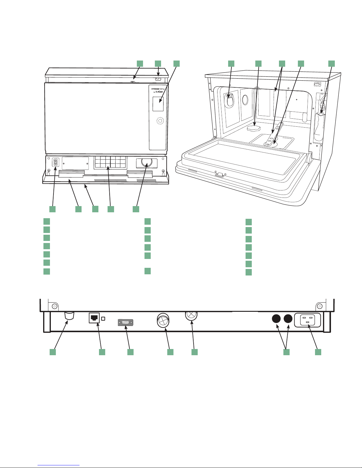
1.2 HYDRIM Unit at a glance
With cover and panels in place
1 2 3 4
20
Figure 1
2
6
2122 825 27
9
10 11
1
n
Power switch
1
1
n
Kickplate
2
1
3
n
HEPA filter
1
4
n
Dryer exhaust
1
5
n
Door latch
1
6
n
USB port
1
n
LCD touchscreen
7
Rear Connections
1
n
Dryer outlet
8
1
n
Water softener
9
1
n
Wash arms (top not shown)
10
1
n
Coarse filter
11
1
n
Cleaning solution
12
1
n
and drawer
1
n
Drain outlet
13
1
n
Ethernet port
14
1
n
RS232 port
15
1
n
Cold water inlet
16
1
n
Hot water inlet
17
1
n
Fuses
18
1
n
Power cable port
19
1
n
Drain tube (behind kickplate)
20
Figure 2
15 19
1714 16 1813
5
Page 6
6
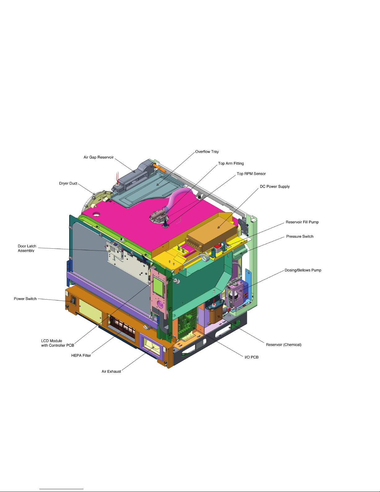
1 Introduction
With cover and panels removed
• Top View (from front right)
Figure 3
Page 7
7
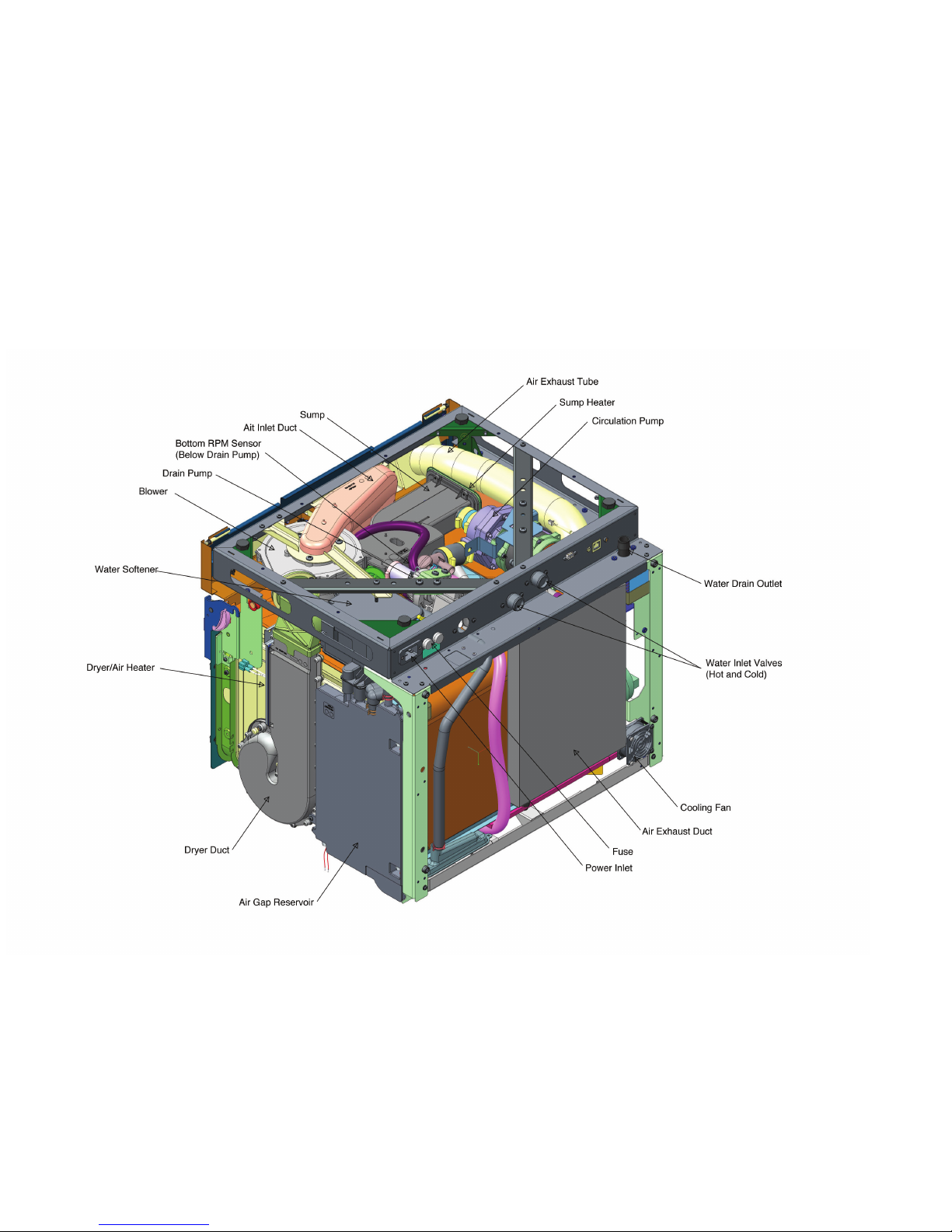
1 Introduction
• Bottom View (from back left)
Figure 4
Page 8

1 Introduction
1.3 Specifications
Machine dimensions: Length: 52 cm 20.5"
Width: 59.8 cm 23.5"
Depth: 52.6 cm 20.7"
Depth with door open: 82.9 cm 32.6"
Weight : 44 kg 97 lbs
Running noise: 65 dB
Hot and cold water connections G 3/4"
Inlet water pressure: 1-10 bar
Incoming hot water temperature: 60°C 140°F
Drain: 3/4"
Drying system: Heater 1 kW
Electrical connection: 208-240VAC ±10%, single-phase,
60 Hz, 12A
Protection class: Class I
Equipment pollution degree: Pollution degree 2
Equipment installation category: Installation category II
Maximum relative humidity: 80% for temp up to 31°C/88°F
50% for temp up to 40°C/104°F
Operating temperature range: 5˚C - 40˚C 41°-104°F
Max. altitude: 2000 m 6,562 feet
Mains supply: + / -10% of nominal
Fuses: 15A, 250V, Type F
8
Page 9
1 Introduction
1.4 Safety information
The following symbols
appear in the margins
of this book.
The following symbols appear on the unit:
Caution: Hot Surface
and/or Hot Steam
A potential hazard
to the operator.
Safe operation
The following apply to both operators and service technicians:
• Exercise caution and seek assistance when lifting or carrying the unit.
• Cleaning solutions may irritate. Avoid contact with eyes, skin and mouth.
• Never lean on the open door. The unit may tip forward causing injury.
• Always turn the unit OFF before adding softener salt or solutions. Before performing
routine maintenance or servicing the unit, turn the unit OFF and unplug the power cord
from the power source.
A situation that
may lead to a
mechanical failure.
Caution: Risk of electrical
shock. Disconnect supply
before servicing.
Important
information
Caution: Refer to manual
for details.
• The operator should never remove the cover of the unit or insert objects through holes
or openings in the cabinetry. Doing so may damage the unit and/or pose a hazard to
the operator.
• If the unit is used in a manner other than that specified, the protection provided by
the equipment may be impaired.
Safe servicing
• The HYDRIM C61w G4 Instrument Washer should only be installed and serviced by
a qualified contractor as it is an Installation Category 2 device. The contractor should be
experienced in installing equipment that requires electrical hook-up as well as plumbing.
• SciCan shall not be liable for incidental, special or consequential damages caused by
any maintenance or services performed on the HYDRIM C61w G4 by a third party or for
the use of equipment or parts manufactured by a third party, including lost profits, any
commercial loss, economic loss, or loss arising from personal injury.
• All local, regional, state, and national regulations regarding the servicing of this class
of device and safety requirements must be observed.
9
Page 10

1 Introduction
When the cover and panels are removed:
• Hazardous voltages are accessible. Disconnect the power cord before removing
the cover or any panels.
• Sharp metal edges are exposed. Be careful, and wear long sleeves and gloves.
Power main
• If the cover or panels are removed, a dielectric strength test (hi-pot) must be performed
on the unit once the cover or panels are reinstalled.
Ground
• If the cover or panels are removed, a protective bonding impedance test (ground
continuity) must be performed on the unit once the cover or panels are reinstalled.
Reporting
• It is vital for SciCan to learn of any problem in the field. This information will help
SciCan solve the problem quickly and improve product reliability in new units.
Biological waste
• Waste water in the unit may contain biological contaminants; use a mechanical means
to siphon the contents. Wear disposable rubber gloves. Dispose of absorbent material
according to biological waste disposal regulations.
1.5 Tools and hardware
Tools required for servicing include:
• Needle-nose pliers
• Wrench
• Nut driver
• Hose clamp pliers
• Screwdriver Philips
• Wire stripper
• Screwdriver slot
• Spring clamp pliers
• Silicone applicator with silicone
The unit contains the following types of hardware:
• Phillips pan head self-tapping metal screws
• Phillips pan head stainless steel machine screws
• Spring clamps
• Band / Gear clamps
• Cable ties
10
Page 11

1 Introduction
1.6 Shipping instructions
The unit should be serviced on site. If it is necessary to send the unit back to the dealer,
follow these instructions:
• Run the ‘Prepare for Shipping’ cycle in the setup menu to remove most of the water
from the system before shipping the unit.
• Use the tube clipped under the front of the unit to drain any residual water from the
air gap.
• If there is standing water in the chamber, siphon or ladle as much water as possible and
use an absorbent cloth to remove the rest.
• Disconnect and remove the cleaning solution container and then drain the dosing reservoir.
• Screw in the leveling legs.
• Specify upright, heated, and insured shipping.
• Ensure unit is returned on a pallet with at least two banding straps securing the box
to the pallet. If original packaging is unavailable packaging can be ordered with
part # 01-113317S.
• Shipping outside of these conditions can affect warranty.
1.7 Installation
IMPORTANT INFORMATION
• To open the wash chamber door if the door is locked and the unit is not functional,
release the lever located on the top edge of the door and pull the door open.
• Ensure that HIP™ Ultra cleaning solution (instrument wash chemical) is available.
All other supplies are included with your unit.
• The HYDRIM C61w G4 is heavy (44 kg). Exercise caution when moving it.
• The HYDRIM C61w G4 must be properly grounded.
• The HYDRIM C61w G4 is equipped with an air gap / anti-suction device to prevent
backflow of dirty water into the water supply. No other air gap device is necessary.
Detailed installation instructions are available in a separate document. Installation should
only be undertaken by a manufacturer approved technician. The use of an unapproved
installer may invalidate the warranty. A separate pre-installation checklist should have been
supplied to the user by the dealer. Please review this prior to approving installation.
If the HYDRIM C61w G4 is installed in a sterilization center, the manufacturer of the
sterilization center should allow enough space at the top, back and both sides of
the unit to facilitate installation, leveling, and service access to the unit.
During installation, all consumables should have been added to the machine as appropriate.
It is important to check that this has been undertaken before starting the machine.
11
Page 12
1 Introduction
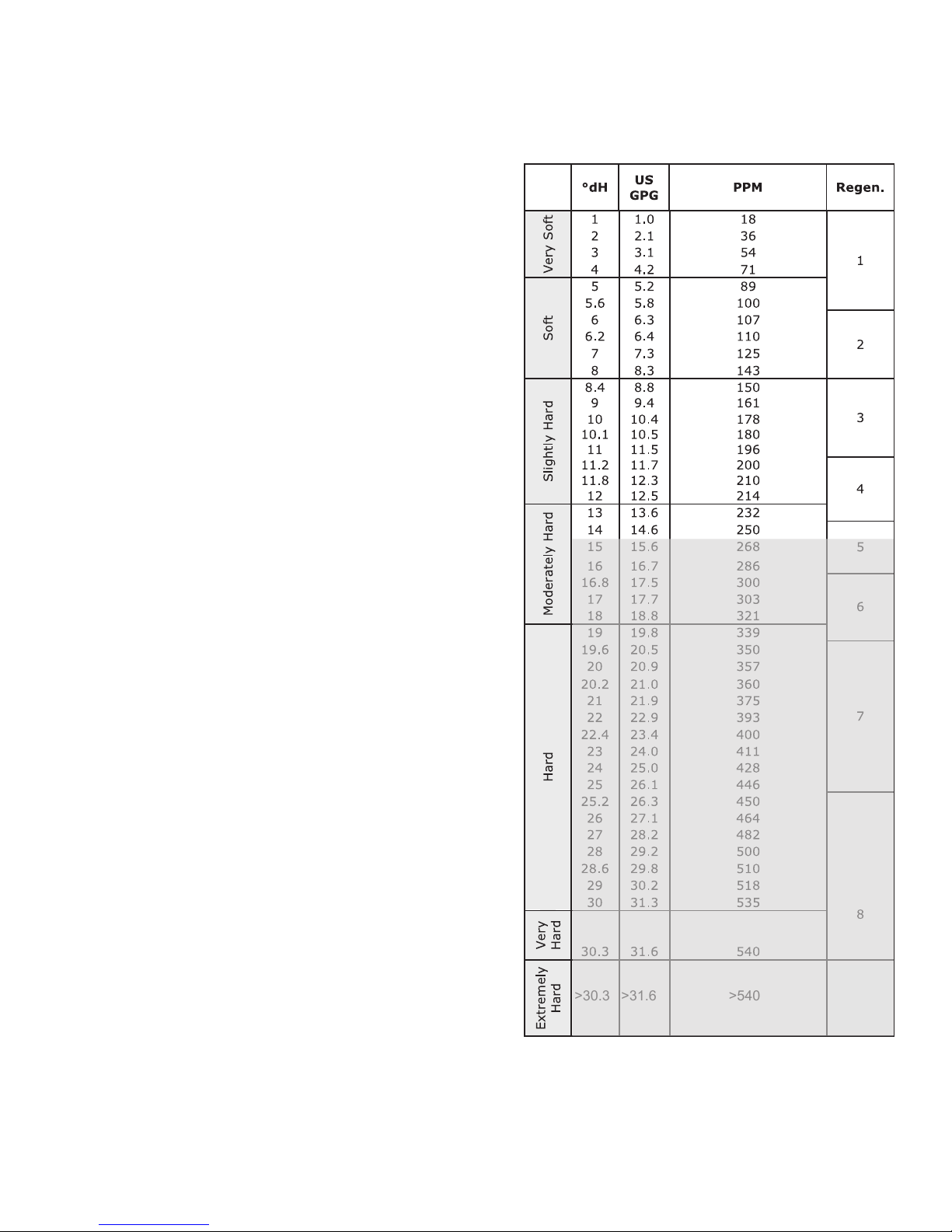
1.8 Setting the water softener
The HYDRIM C61w G4 is equipped with
a built-in water softening system that must
be adjusted according to the local water
hardness. To read local water hardness,
proceed as follows:
1. The water test kit included with your
HYDRIM contains three water
hardness test strips in bags. Take a
water sample from the location where
the machine will be installed.
2. Open one of the bags, remove the
test strip and dip it into the water.
3. Compare the color of the strip with
the chart on the back of the bag
Determine the water hardness according
to the chart on the water test kit envelope.
Water hardness and salt regeneration levels
*
4. Power the unit on and select the
Settings key from the main menu.
5. Go to the Setup Menu, Cycle Settings,
and select “Set Regeneration”.
7. Using the up and down arrows, set the
water softener regeneration level
according to the water hardness table
in this section. If your water hardness
falls between two settings, select the
higher setting.
8. Unscrew the water softener container
lid from the bottom left of the chamber
and pour 0.5 litres of water into the
water softener container.
9. Add 0.5 kg of water softening salt to
the water softener container, using
>30.3 >31.6
>540
the supplied funnel to prevent any salt
from spilling into the chamber, and close
by screwing the lid tightly back into place. An improper seal can lead to corrosion.
Additional
Water
Water
treatment
treatment
required
required
*Please note: The water test strip is only accurate up to 250 ppm. If the reading on the test strip exceeds
250 ppm and/or if the location in which the HYDRIM is installed has known water quality problems, having
a more detailed and accurate water test done by a test lab is strongly recommended.
12
Page 13
1 Introduction
IMPORTANT: The HYDRIM’s water softening system reduces the water hardness by
taking out Calcium Carbonate. If the water testing results show that the water hardness
is outside the unit's range of adjustment, or if other dissolved solids in the water cause
stains or deposits on the instruments or chamber, an external water treatment system may
be required.
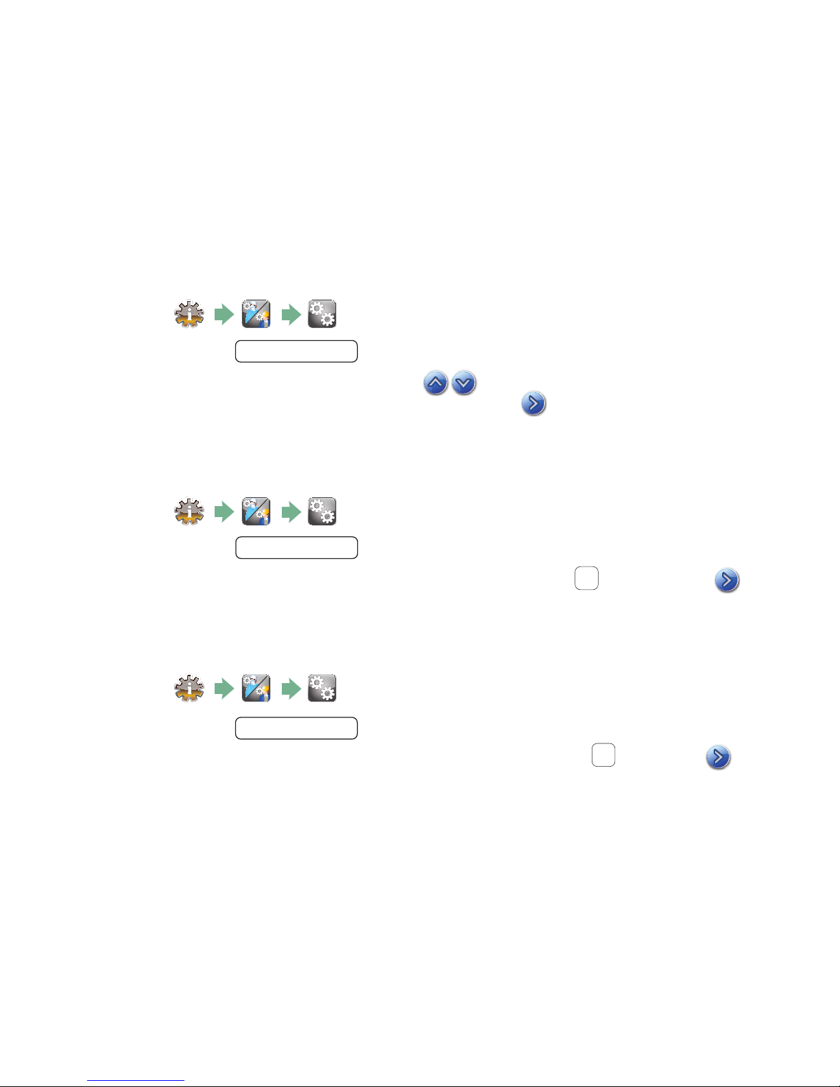
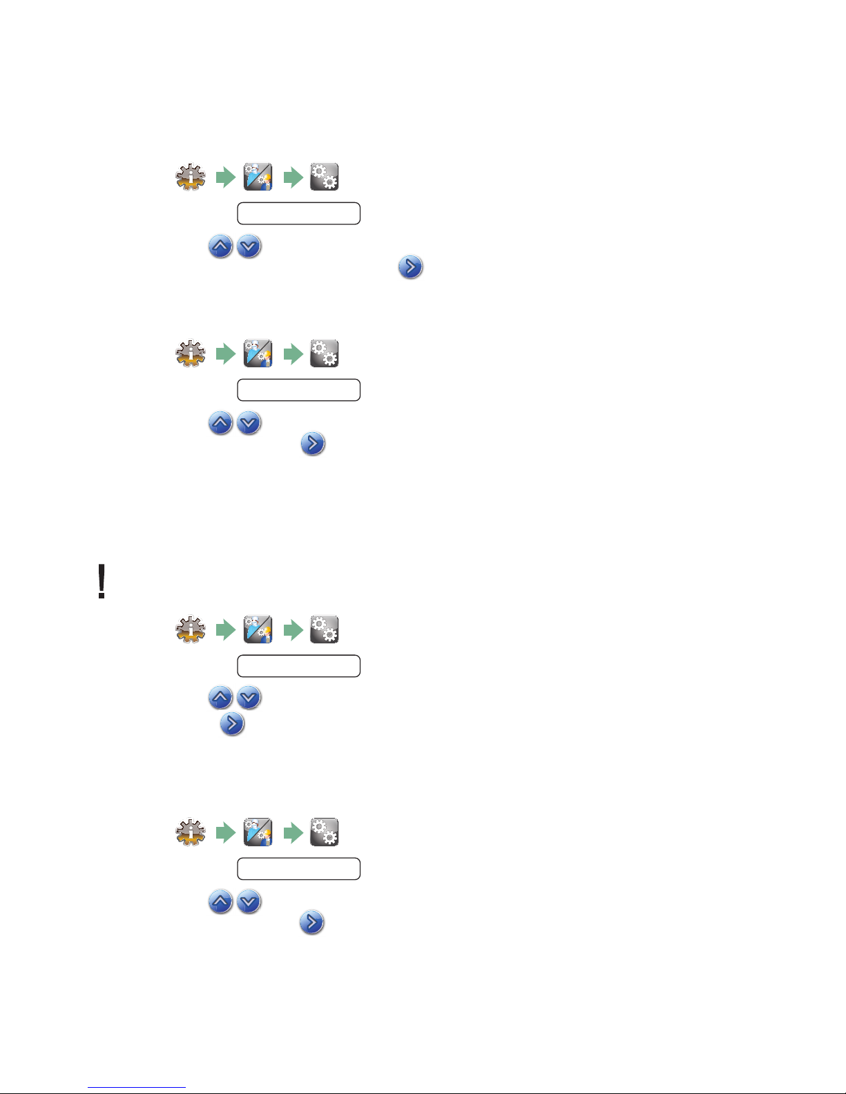
1.9 Setting the language
The messages displayed by your HYDRIM can be presented in a number of different
languages. To change the current language, follow these steps:
1.
2. Scroll to
Language Selection
and select.
3. From the LANGUAGE screen, press to scroll through the list of languages.
When you have found the desired language, press to save your selection and return
to the Setup menu.
1.10 Setting the country
1.
2. Scroll to
3. Using the keypad, type the name of the country and press
to save and return to the Setup menu.
Country
and select.
EN
to select. Press
1.11 Setting the time
1.
2. Scroll to
Date/Time
and select Time Setup.
3. From the TIME screen, use the keypad to set the time. Press
to return to the Setup menu.
13
EN
to save and
Page 14
1 Introduction
NOTE: If the HYDRIM is connected to a network, it is important to also enter the correct
Time Zone. Enter the Time submenu, select Time Zone and scroll and select your local
time zone.
4. To change your unit to display 12-hour time format (24-hour time format is the default
setting), go to the Setup menu and use to scroll to TIME 12/24, select it and
toggle to 12. Press to save and return to the Setup menu.
5. To activate daylight savings time (DST), go to the Setup menu and use
to DST ON/OFF and select. Use
to save and return to the Setup menu.
to toggle DST ON or OFF and press the
to scroll
1.12 Setting the date
1.
2. Scroll to
3. From the DATE screen, use the keypad to set the date. Press
to return to the Setup menu.
Date/Time
and select Date Setup.
EN
to save and
4. To change the format in which the date appears, return to the Setup menu and use
to scroll to DATE FORMAT. Select it, and follow the prompts to have
the date displayed in the desired format. Press to save and return to
the Setup menu.
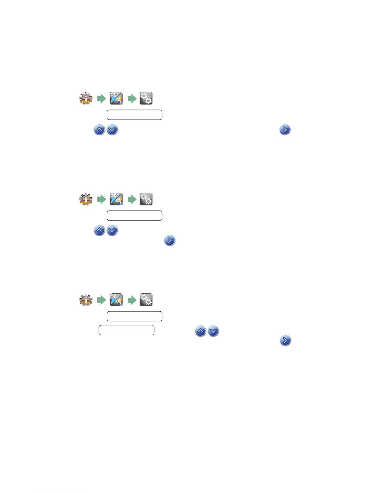
1.13 Assigning unit identifier number
1.
2. Scroll to
Unit No
and select.
3. Using the keypad, select a maximum of 3 digits to be used as the unit’s identifier
number. Press EN to save and to return to the Setup menu.
1.14 Resetting the drying counter
The drying counter must be reset when the HEPA filter is changed. User will be prompted
every 750 cycles to do preventative maintenance, which is triggered by the reminder to
change the HEPA filter. To reset the drying counter, follow these steps:
1.
2. Scroll to
3. Select Default 0 to reset. This will stop the reminder to the end user.
Reset Drying Counter
and select.
14
Page 15
1 Introduction
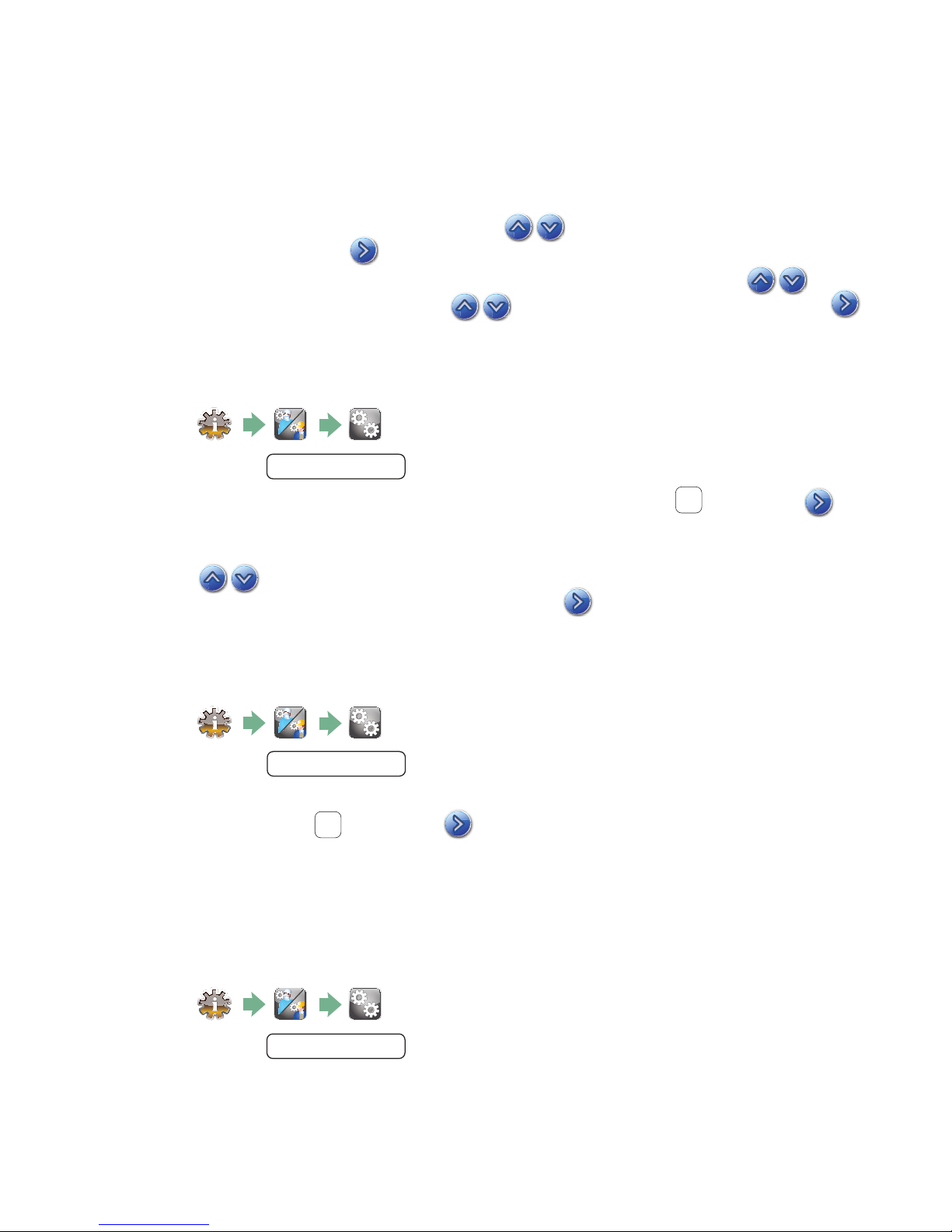
1.15 Adjusting the screensaver delay
To change the length of time before the screensaver is activated, follow these steps:
1.
2. Scroll to
Screensaver
and select.
3. Use to scroll through your time options. When you have found the amount of
time you require, press it. Press to save and return to the Setup menu.
1.16 Adjusting the temperature display
1.
2. Scroll to
Temperature C/F
and select.
3. Use to choose between having information displayed in degrees Celsius or
Fahrenheit. Press to save and return to the Setup menu.
1.17 Turning the button sound ON or OFF
The HYDRIM is preset to beep when a button is pressed. If you would like to turn the button
sound off, follow these steps:
NOTE: Turning OFF the button sound does NOT turn off other alarms and cycle notification
beeps.
1.
2. Scroll to
Beep ON/OFF
and select.
3. Use to scroll through your ON or OFF options and select it by pressing it.
Press to save and move back to the Setup menu.
1.18 Adjusting the button beep volume
If you would like to adjust the beep volume, follow these steps:
1.
2. Scroll to
3. Use to scroll through the volume settings. Select the one you want by
pressing it. Press to save and move back to the Setup menu.
Beep Volume
and select.
15
Page 16
1 Introduction
1.19 Adjusting the salt regeneration
Salt regeneration should be set according to the local water hardness. See section 1.8
Setting the water softener for instructions on determining correct settings. To set salt
regeneration, follow these steps:
1.
2. Scroll to
Set Regeneration
and select.
3. Use to change the value. The default setting is 1. Press to save and return
to the Setup menu.
1.20 Adjusting the screen contrast
The touchscreen is calibrated for the lighting condition of most sterilization centers. Should
you need to adjust the contrast for your office, follow these steps:
1.
2. Scroll to
LCD Contrast
and select.
3. Use to scroll through your contrast options. When you have found the contrast
you require, press it. Press to save and return to the Setup menu.
1.21 Changing the touchscreen display themes
The touchscreen themes (i.e. icons and background colours) can be changed to one of the
preset options. To change themes follow these steps:
1.
2. Scroll to
3. In the
As you scroll, each theme will display on the touchscreen. Press to select your
theme and return to the Setup menu.
Theme
Change Theme
and select.
screen, use to scroll through your available options.
16
Page 17
1 Introduction
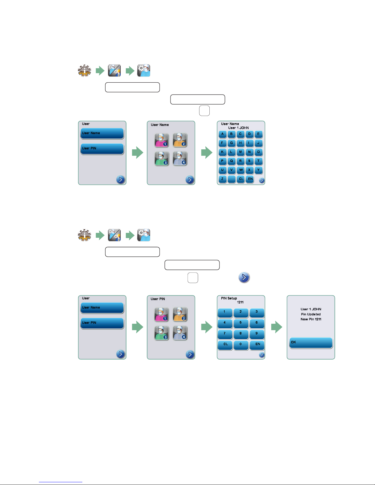
1.22 Creating a User Name
Up to four unique User Names can be created. To assign a User Name follow these steps:
1.
2. Scroll to
3. To assign a user name, select
a name (up to 12 characters) and press EN to save.
User
and select.
User Name
and use the alphabetic keypad to enter
1.23 Creating a User PIN
From the User PIN screen, you can assign up to four PINs. To assign a PIN, follow these
steps:
1.
2. Scroll to
User
and select.
3. To assign a user PIN, select
a number (up to 4 digits) and select EN to save and to move to the confirmation
screen.
User PIN
and use the numeric keypad to enter
5. If all of the information presented in the confirmation screen is correct, press OK
to be returned to the User PIN screen. To make a correction, select the User PIN you
want to change and repeat the process described above.
17
Page 18
1 Introduction
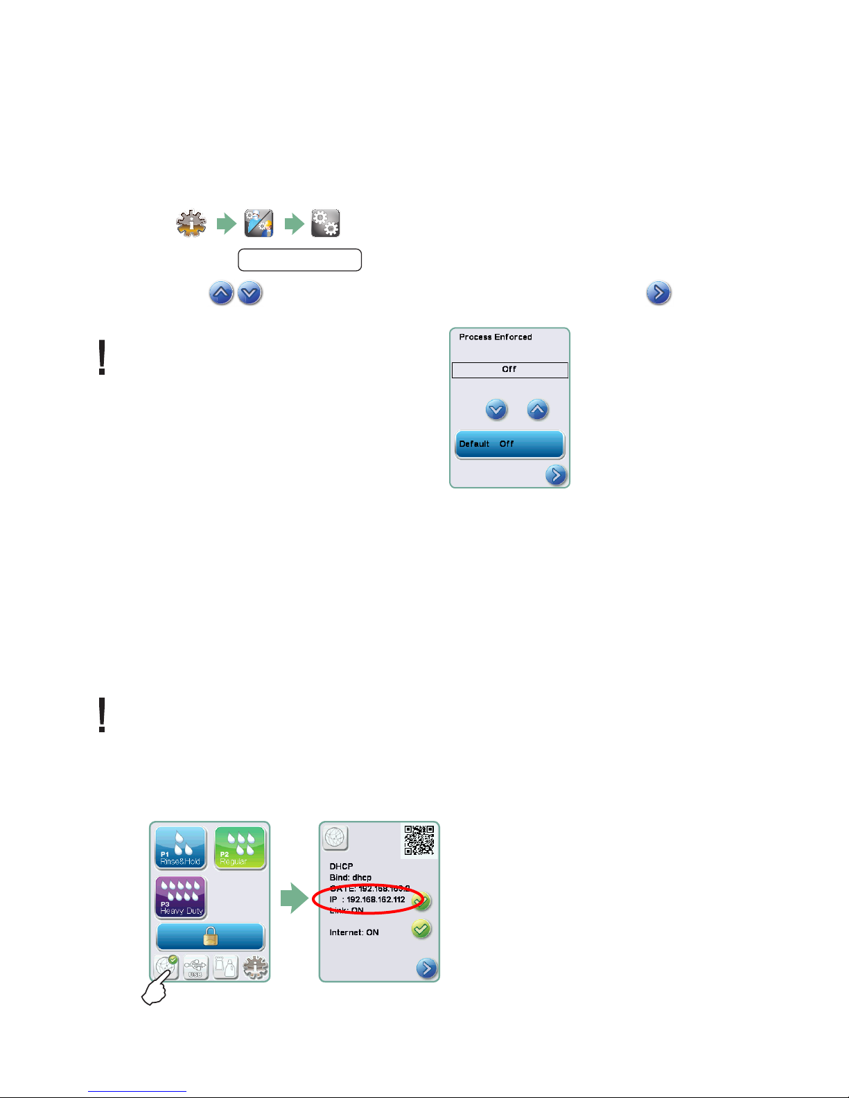
1.24 Setting up process enforced usage
When process enforced usage is activated, users are required to enter a PIN at the end of
a cycle. For process enforced usage to function, User IDs and PINs must first be assigned.
To set up User ID and PINs, refer to sections 1.22 and 1.23 on creating a user name and
PIN. To activate process enforced usage, follow these steps:
1.
2. Scroll to
Process Enforced
and select.
3. Use to toggle process enforced function ON or OFF. Press
to save your selection and return to the Setup menu.
NOTE: Any user can stop a cycle even
with process enforced usage ON.
However, the cycle data will record
that an unauthorized user
has stopped the cycle.
1.25 Connecting to a network
The HYDRIM C61w G4 has a 10/100Base-T Ethernet port located at the back of the unit.
To connect your HYDRIM to a network using a router, follow these steps:
1. Connect your network cable to the Ethernet port at the back of the unit. If your office
uses a router, the router should automatically assign the unit an IP address. A red X on the
network icon means the unit is not connected. A yellow check mark means the unit has
an IP address but is not connected to the Internet and cannot send emails. A green check
mark means the Internet connection is set up properly and the unit can send out emails.
NOTE: In some circumstances, where you do not have a router, for example when using
Windows Network Sharing, you may have to assign a dedicated or ‘static’ IP address.
To assign a static IP address, contact your local network administrator.
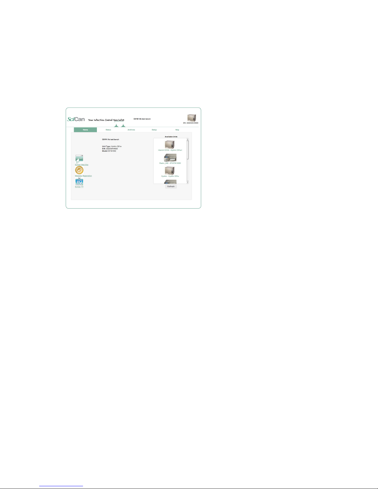
2. From the main screen, press the Network icon. The Network screen displays information
about your HYDRIM’s connectivity, including its IP address.
18
Page 19
1 Introduction
3. Type the IP address displayed on the touchscreen into the browser of any web enabled
device to access your unit’s web portal. When the Network icon is active (for example when
sending email) it will turn green.
NOTE: Use QR code if connecting to a mobile device.
NOTE: Connection time will vary depending on your network speed, and making an initial
connection can take longer.
1.26 Connecting to a wireless network
The HYDRIM can be configured for wireless use by connecting the Ethernet port to an
external wireless bridge / access point. SciCan currently recommends the use of the
D-Link® DAP-1522 Xtreme N® Duo Wireless Bridge. Contact your network administrator
to learn more about setting up a wireless bridge.
19
Page 20
2 Routine Procedures and Maintenance
2 3 4 5 6 7
3 4 5 6 7
4 5 6 7
www.scican.com
Lot number:
L0T334.11.2012
Product: CS-HIPC-U
8X 750ML /
25.4 U.S. fl. oz.
7
5 6 7
6 7
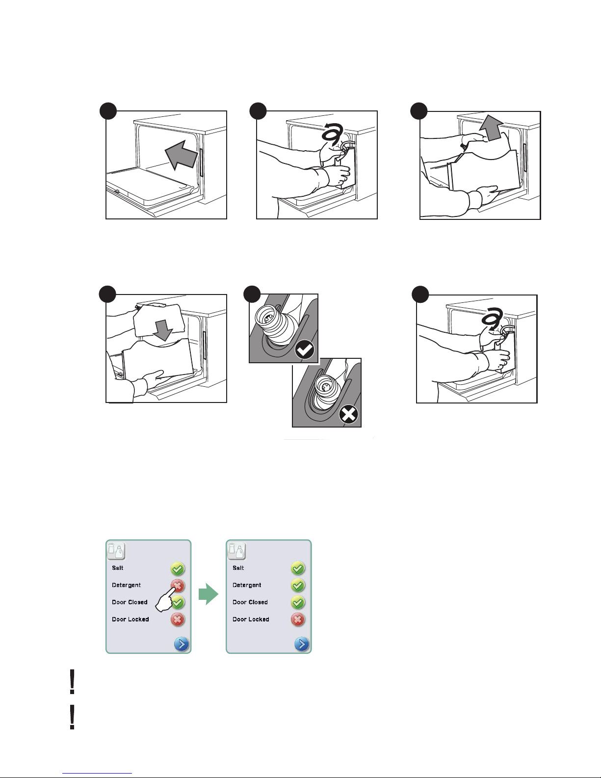
2.1 Replacing the HIP™ Ultra cleaning solution
To replace the cleaning solution, follow these steps:
1
2
3
Turn the power OFF,
open the door and pull out
the chemical drawer.
4
Place a new bag
in the chemical drawer.
To prime the cleaning solution dosing pump, press the water softener/detergent icon on the
main screen. In the water softener/detergent screen, press the red X next to “Detergent”.
The unit will prime the dosing system and a green check mark will appear in place of the
red X when it is ready for use.
Disconnect the cleaning
solution connector.
5
Ensure the nozzle is
in the correct position.
Remove the empty cleaning
solution bag and discard
or recycle it.
6
Connect the new bag,
close the door and
power ON the unit.
NOTE: The system can also be primed by simply starting a cycle and selecting “Detergent
Replaced”, when prompted.
NOTE: A cycle will not start with the red X next to the “Detergent” indicator.
20
Page 21
2 Routine Procedures and Maintenance
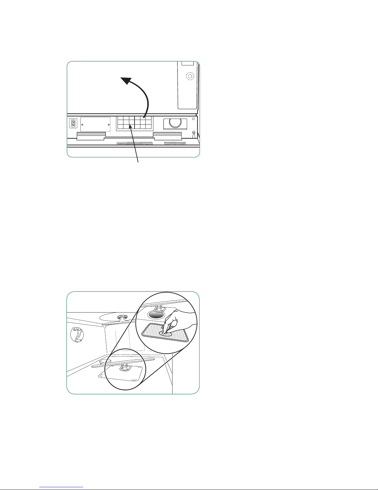
2.2 Changing the HEPA filter
When the message “Replace air filter”
appears, the HEPA filter is in need of
changing. To change the filter, proceed as
follows:
1. Open the kickplate below the front door
of the unit and turn the power off.
2. Remove the old filter by pulling it from
the centre.
3. Install the new air filter and close the
Figure 5
HEPA filter
kickplate.
4. After replacing the filter, go to the
“Reset Drying Counter” screen in the
Setup menu and reset the drying counter
to zero.
5. The filter must be replaced every 750
2.3 Filter and wash arm maintenance
Cleaning the chamber’s coarse
and fine filters
Inspect the coarse and fine filters in the
bottom of the chamber daily for debris and
clean if necessary. To clean, remove the
filter (turn the metal nut at the centre front of
the filter to release it), rinse under a tap and
reassemble. Ensure that the filter is firmly
locked into position when replaced.
drying cycles. The unit will continue to
run if the filter is not replaced, but the
drying performance will decrease. (Part
number 01-113277S Filter-Air, C61)
Figure 6
21
Page 22
2 Routine Procedures and Maintenance
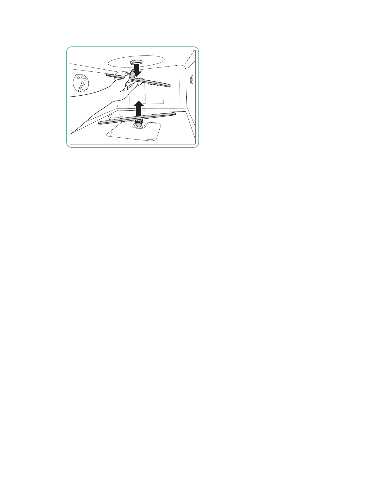
Removing and checking the wash arms
If you see that the wash arms are not
turning easily, remove them. Both the upper
and lower arms are pressure mounted.
To remove the upper arm, pull down and to
remove the lower arm, pull up. Rinse under
a tap, clear obstructions from outlet holes
and reassemble.
Figure 7
2.4 Cleaning the chamber
The HYDRIM C61w G4 chamber can be cleaned using the “Cleaning” program in the User
menu. This cycle is used to periodically remove hardwater deposits from the chamber walls
and racks. Pour 0.5 litres of vinegar into the chamber before starting the cycle. From the
User menu, select “Cleaning” and a cleaning cycle, similar to a normal wash cycle, will run.
The user will be prompted to clean the chamber every 25 cycles. Reminder frequency can
be changed to 25, 50, or 100 cycles. To do this, enter the Technician menu.
2.5 Draining the unit for service or shipping
To drain the unit prior to shipping, or before tipping it onto its back for servicing, run the
“Prepare for Shipping” cycle. Once complete, drain any water remaining in the air gap using
the silicone tube located under the centre of the unit’s kickplate.
2.6 Upgrading the firmware
Instructional videos are availabel on http://updates.scican.com
Upgrading the Interface Software can be done from a USB drive, a MicroSD card or
a web site. The easiest and fastest method is to use a USB drive.
To upgrade the firmware using a USB drive, proceed as follows:
1. Download new firmware. The firmware will be made available on updates.scican.com or
emailed from SciCan upon request. It will be packed into a zip file (e.g. SL00R1XX.zip is
the name of the current revision file, but the number will change with every revision) and
must be extracted to a USB drive.
2. Check that you have the following files on the USB Drive:
• rmware.ini
• Firmware(Folder)
• SL00R100_4_100_CAA29608.sci
• cp.bat
22
Page 23

2 Routine Procedures and Maintenance
3. With the unit powered OFF, insert the USB drive loaded with the firmware update.
4. Power ON the unit. The firmware will be updated automatically using the USB drive.
This should take approximately 6 minutes.
NOTE: The USB icon on the LCD touchscreen will flash green while it is active. Do not
remove the USB key while it is active.
5. When it is complete, the “Firmware.log” file on the USB drive will include the result of
the upgrade (file name, upgrade OK, or upgrade failed, and for what reason).
6. Whether the upgrade is successful or unsuccessful, the “firmware.ini” file on the
USB drive will be automatically deleted.
7. To retry or upgrade another unit, insert the USB drive into the PC’s USB port (NOTE
there is currently no Mac version) and double-click the “cp.bat” file in the Firmware
folder. Then remove the USB drive and repeat Steps 2 to 5.
2.7 Using the HYDRIM remote access function
Users can allow offsite technicians to remotely access the LCD touchscreens and web
portals of HYDRIM C61w units connected to a network. This can be done either from within
a network or from outside a network.
From within a network:
For local network remote access, the unit must be connected to a network. See Connecting
to a network in section 1.26 of this manual for more details. From the unit’s web portal,
proceed as follows:
From the TOOLS page, click on the LOCAL CONTROL tab.
Log in using the following credentials:
Username: scican
Password: s23can173
Click on the start button to start a local connection. It will open up a page that mirrors the
HYDRIM unit’s touchscreen so that it can be controlled remotely within a local network.
From outside a local network:
For remote access of a HYDRIM web portal or touchscreen from outside a local network,
proceed as follows:
1. Someone onsite with the unit or from within the network must provide access to an
outside user by generating a ‘token’ (or access code).
23
Page 24

2 Routine Procedures and Maintenance
2. To generate a unique token using the web portal, go to the TOOLS page and click on
the REMOTE ACCESS tab.
3. To generate a unique token using the unit’s LCD touchscreen, go to the SETUP menu
and scroll to REMOTE ACCESS and follow the prompts to enable remote access.
4. The technician attempting to access the unit from outside the network will need to go to
the following URL: http://updates.scican.com and enter their registered email address,
password, token and HYDRIM Serial Number (optional).
5. To create a new account to enable remote access for a HYDRIM , click on the CREATE
NEW ACCOUNT link, complete the form, and click on the SUBMIT FORM link. The
system will send a confirmation email to verify the account. Once confirmed, the
account will be ready to use.
6. Use the valid user name and password to enter Updates.scican.com and enter the
token when prompted. This will bring you to the HYDRIM unit’s web portal page.
7. Click on SETUP. A username and password prompt will appear. Log in using the
following credentials:
• Username:scican
• Password:s23can173
8. Upon authentication, go to TOOLS and click on REMOTE ACCESS. Click on the start
button to start a connection. It will open up a page that mirrors the HYDRIM unit’s
touchscreen so that it can be controlled remotely from outside its local network.
Use your mouse to click and select touchscreen elements.
2.8 Annual Service Requirements
The HYDRIM C61w G4 is designed to be maintenance free; however, it is recommended
that a SciCan-approved service technician perform an annual check.
The following checks are recommended in order to maintain optimum performance of
the unit.
Annual service schedule
• Checkintegrityofincomingandoutgoingservices(power,watersupply,drain)
• Checkwatersupplyinlineltersandcleanasappropriate
• Checkgeneralconditionofmachine
• Replacedryerlterandresetdryercounter(onlyifrequired)
• Inspectandreplacemainchamberseal(onlyifrequired)
• Inspectandreplacelowerdoorseal(onlyifrequired)
• Checksolutioncontainerconnectionforleaks
• Checksaltlevelandreplenishasrequired
• Checkwaterhardness(teststrips)andadjustsaltregenerationsettingsifrequired.
24
Page 25

2 Routine Procedures and Maintenance
• Inspectandcleansumplters(checksumpfordebris)
• Checkwasharmsforblockagesandremovethemforcleaningifrequired.
• Reviewerrorhistory
• Softwareupgrade(ifnecessary)
• Checkindividualcomponentfunctionality.Gotothetechnicianmenu(enteraccess
code 7919) and select ‘Diagnostic Tools’ then select ‘Component Tests’. From here
you can scroll through and check the functionality of the following components:
• Coolingfans
• Airgappump
• ROvalve(iftted)
• Condenservalve(iftted)
• Chamberheater
• Doorlatch
• Saltregenerationvalve
• Dosingpump
• Dryer
• Hotwatervalve
• Coldwatervalve
• Airsolenoidvalve(iftted)
• Wastepump
• Recirculationpump
• Checkprogramselection
• Checkdosingpumpvolume;dosingpumpispre-calibrated.Volumecannot
• be adjusted.
• Checkthermocouplecalibrationandadjustifrequired.
• Resetservicecyclecounter
• Cleanmachine
• Conductelectricalsafetytests
Equipment and parts requirements for annual service
• Dryerlter(HEPA)(Partnumber01-113277S)
• Mainchamberseal(Partnumber01-113300S)
• Lowerdoorseal(Partnumber01-113661S)
• ServiceManual(Partnumber95-113023)
• Electricalsafetytestequipment
• Waterhardnessteststrips(Partnumber01-108305S)
• Calibratedindependenttemperaturemeasuringdevice
• 100mlgraduatedmeasuringcylinder
25
Page 26

3 Diagnostics and Troubleshooting
3.1 Using the service menu
To access the service menu, select the image of the technician and enter
the service code 7919 on the keypad.
User Technician Setup
Wash Test
Diagnostic Tools
Error History
View IO Status
Component Tests
Set Debug Screen
Set Calibration
Cycle Settings
Set Regeneration
Chemical Setup
Cycle Selection
Prewash
Wash
Rinse
Set Drying Time
RO Selection
Set RO water level
Rinse continuous
Factory Default
Repeater Mode
Production Tools
Prod Test Cycle 1
Prod Test Cycle 2
Water Adjustment
SW Upgrade
Network Setup
Subnetmask
Router
DNS
Automatic IP (DHCP)
Renew IP
IP Address
Dealer ID
Preventative Maintenance
Set Cleaning Warning
26
Page 27

3 Diagnostics and Troubleshooting
3.2 Using the setup menu
To access functions and settings on the setup menu, proceed as follows:
User Technician Setup
Language Selection
Country
Date/Time
Unit No.
Network Setup
Reset Drying Counter
Screen Saver
Temperature C/F
Set Printer
Baud Rate
Set EOL CR/LF
Set Regeneration
LCD Contrast
Theme
Remote Screen
Instructions
Prepare for Shipping
Set Button Beep
Beep Volume
Instruction Delay
Remote Access
27
Page 28

3 Diagnostics and Troubleshooting
3.3 Using the user menu
To access functions and settings on the user menu, proceed as follows:
User Technician Setup
Cleaning
Set Drying Time
Set Wash Time
Cycle Count
Process Enforced
User
28
Page 29

3 Diagnostics and Troubleshooting
3.4 Using software tools for diagnostics
Within the service menu, there are two useful tools for troubleshooting: Debug screen
and IO status screen.
Debug Screen
The Debug screen is used when running a cycle to view the I/O status of components.
To access the debug screen, select Diagnostic Tools from the service menu and select
Set Debug Screen, then go to the main menu and select a cycle. The LCD screen will
display the following:
Hot and Cold
Chemical level
Regeneration valve
Validation
Dosing pump
Lower arm rpm
Ambient temperature
Dryer air temperature
3.4 Using software tools for diagnostics
Within the service menu, there are two useful tools for troubleshooting: Debug screen and
IO status screen.
Debug Screen
The Debug screen is used when running a cycle to view the I/O status of components.
To access the debug screen, select Diagnostic Tools from the service menu and select
Set Debug Screen, then go to the main menu and select a cycle. The LCD screen will
display the following:
Figure 8
Upper arm rpm
Air gap
Empty/Full/Over
flowing
Chamber temperature
Air gap valve
and pump
Door status
Dryer / Heater
Salt level
Condenser valve
Evacuation pump
Valves
NOTE: When a cycle is started (P1, P2, P3) the air gap is filled four times before
the circulation pump starts.
Temperature
29
Page 30

3 Diagnostics and Troubleshooting
I/O status screen
The IO status screen is used when testing components and wires for functionality
without the cycle running.
30
Page 31

3 Diagnostics and Troubleshooting
3.5 Troubleshooting cycle faults
Cycle Fault Effect Problem Possible Causes
CF 1 Water Heating
Failure
CF 2 Chamber Filling
Failure
CF 3 Chamber
Temperature Sensor
Reading Failure
CF 4 Water
Evacuation Failure
CF 7 Cycle Aborted or
Interrupted
Improper wash, cycle
aborted
Improper wash, cycle
aborted
Improper wash, cycle
aborted
Cycle interrupted
Cycle interrupted Stop button pressed or
Chamber temperature
less than a set point
after a timeout,
or a temperature
increase rate of 1ºC
per 2 minutes was
not achieved during
“Circulation and
heating” phase
Timeout on filling up
the chamber
Temperature reading
outside acceptable
range for primary or
secondary sensor
Timeout on water
evacuation from
the chamber
power failure
31
This is caused by a water
heater malfunction:
• Check water heater
wire harness for loose
contacts.
• Check for open thermal
cut-off switch due to
high temperature.
• Check that the
heater element is not
interrupted.
• Check I/O PCB water
heater relay output.
• Water supply issue
• Water valves failure
• Air gap water pump
failure
• Air gap valve failure
• Air gap Full/Empty level
switches failure
• Chamber water level
pressure switch
malfunction
• Overflow switch
malfunction triggering
evacuation pump.
This is caused by a
temperature sensor
malfunction:
• Check temperature
sensor wires for loose
contacts.
• Replace sensor with a
good one and verify if
the CF persist.
• Replace I/O PCB.
• Blocked drain tube
• Chamber water level
switch malfunction
• Chamber water
evacuation pump failure
• Drain pump priming
connection hole in the
sump blocked
• Cycle aborted due to
loss of power
Page 32

3 Diagnostics and Troubleshooting
Cycle Fault Effect Problem Possible Causes
CF 8 Cycle Fault
CF 9 Program
Timeout
CF 10 Drying System
Error
CF 13 Temperature
Validation Error
CF 14
CF 15 Chamber
Overflow
Drying aborted Air temperature less
than a set point after
a timeout
Cycle interrupted The unit is running
a cycle for more than
3h ±3 min.
Cycle interrupted Air Dryer RPM not
zero when Dryer motor
should not be activated
Cycle interrupted Water temperature rose
above the maximum
allowed temperature
Cycle interrupted During the Prewash
phase the water
temperature in the
chamber is 5ºC higher
than the target for more
than 1sec
Cycle interrupted Leak in the unit The water reservoir overflow
This is caused by a heater
malfunction:
• Check air heater wire
harness for loose
contacts.
• Check that the
heater element is not
interrupted.
• Check I/O PCB air
heater relay output.
• Defective PCB and/or
software failure
• Replace Color LCD
controller.
Electronics – motor driver
failure (I/O board)
• Check Dryer motor
wiring.
• Verify that motor stops
when in non drying
phase.
• Replace I/O board.
• Replace dryer motor.
The temperature sensor out
of range:
• Check temperature
sensor wires for loose
contacts.
• Run cycle to monitor
that the water
temperature is below
96°C.
• Replace sensor and
verify if the CF persist.
• Replace I/O PCB.
switch was triggered:
• Check the water
reservoir full switch.
32
Page 33

3 Diagnostics and Troubleshooting
Cycle Fault Effect Problem Possible Causes
CF 16 Ambient
Temperature Error
CF 17 Cycle Fault
CF 21 Dosing System
Error
CF 22
Air Temperature error
CF 23 Top RPM error
CF 24 Low RPM error
Cycle interrupted Operating temperature
for one or both logic
boards is too high
Drying Air temperature
above a set point
Dosing System failure
Cycle interrupted
Cycle cannot start or
cycle interrupted
Cycle interrupted Top RPM lower than
Cycle interrupted Low RPM lower than
Dosing system failed
to dispense the preset
amount in a predefined
time (timeout is 3.5s/
pulse). Dosing reservoir
level switch does not
change from Full ON
to OFF by the end of
dosing (no chemical
dispensed)
Ambient temperature
sensor broken
10 while washing or
disinfecting
25 while washing or
disinfecting
The room or enclosure is too
warm and not allowing the
unit to adequately cool:
Check that fans are working.
The air temperature in the air
duct is too high:
• Check dryer motor.
• Verify that the air heater
is not always ON.
• Verify air temperature
sensor.
• Verify I/O PCB.
Dosing pump or switch error:
• Verify bellows dosing
pump
• Verify bellows dosing
pump switch
Temperature sensor
reading error:
• Check air temperature
sensor wires for loose
contacts.
• Replace sensor with
a good one and verify
if the CF persist.
• Replace I/O board.
• Instrument blocking
upper wash arm
• Chamber water level
too low
• Water pump failure
• Instrument blocking
lower wash arm
• Chamber water level
too low
• Water pump failure
33
Page 34

3 Diagnostics and Troubleshooting
Cycle Fault Effect Problem Possible Causes
CF 25 Vref Error
CF 27 Memory Error
Touchscreen is blank/
white
USB storage device
does not contain
the last print out
Unit is not sending
emails
Not receiving emails
from the unit
Cycle cannot start or
cycle interrupted
Hardware failure Color LCD control
Vref and VCC drift, post
CF 25 if VCC and Vref
are more than 3% apart
(power supply error)
board failure
The power supply 5V output
voltage is fluctuating:
• Check power supply 5V
output.
• Replace I/O board.
The internal memory of
the Color LCD Controller
is malfunctioning:
• Replace Color LCD
controller board.
Check power source
Re-insert the USB storage
device and wait for the
data to copy over again. If
problem persists, back up all
the information on the USB
device and reformat it.
NOTE: the web portal allows
access to all of the unit’s
cycle information.
Check email settings by
using the TEST button on
the unit’s web portal.
From the SETUP web page,
select the TOOLS tab.
Click on TEST to check
your router, unit, and Internet
connections. If all settings
appear to be OK. Go to
the unit’s touchscreen
and renew
the IP address by following
these steps:
1. Scroll through the setup
menu to NETWORK
SETUP and select.
2. Select RENEW IP.
Check user’s spam filter.
Be certain the unit has been
identified as an accepted
email source.
34
Page 35

4. Removing and Replacing Panels
WARNINGS AND
PRECAUTIONS
If you have questions about the unit you are repairing, please do not hesitate to
contact your local SciCan representative for information. Also, the HYDRIM is
heavy. Exercise caution and seek assistance when lifting or carrying units.
EXERCISE CAUTION
• Hazardous voltages are accessible when the cover is removed.
• Disconnect the power cord before servicing the power mains portion of the
controller board and associated devices.
• Removing the panels will expose some sharp metal edges. Be careful and wear
long sleeves and gloves.
PERFORM TESTS
• If panels are removed, a dielectric strength test (Hi-Pot) AND a protective
bonding impedance test (ground continuity) must be performed on the HYDRIM
when the work is completed and after the cover has been returned to the unit.
• A dielectric strength test (hi-pot) must be performed on the unit if parts
associated with the power main are serviced or replaced.
• A protective bonding impedance test (ground continuity) must be performed
on the unit if components of the protective earthing system are changed or if
connections are broken and remade.
PROTECT THE UNIT
• The HYDRIM contains electronic circuitry that is static sensitive. Always wear
a static strap when working with or near printed wiring boards. In addition, use
static footstraps, grounding mats and grounded work surfaces when servicing
microprocessor devices. Transport boards and devices in static protected bags.
• In order to ensure adherence to the applicable safety agency approvals,
state, provincial, regional and national laws, replace components with SciCan
approved parts only.
35
Page 36

4. Removing and Replacing Panels
4.1 Removing and reinstalling the top panel
1. Open door to remove 3 screws under the top cover’s
front edge. (Figure 9)
2. Pull top cover to the front and tip up to remove.
To reinstall, place the cover on top of unit and slightly forward.
Push it to the back to engage the tabs. Replace 3 screws at
the front.
Top panel – part # 01-113286S
4.2 Removing and reinstalling the left panel
1. Remove top cover.
2. Open front door to remove 4 screws in the front. (Figure 10)
3. Remove 3 screws on back of unit. (not shown)
4. Tip the panel back and slide it down to disengage
the two tabs that insert into the chassis at bottom.
To reinstall, bring the panel into position slightly lower than
the unit to be able to engage the two bottom tabs and
the one at the top. Slide it up into place and replace 4 screws.
Replace the top cover.
Left side panel – part # 01-113288S
screws
screws
Figure 9
Figure 10
36
Page 37

4. Removing and Replacing Panels
4.3 Removing and reinstalling the right panel
1. Open the door to remove 3 screws in the front. (Figure 11)
2. Remove 3 screws at the back of the unit. (not shown)
3. There are 2 tabs at the bottom of the panel. To disengage these
from the chassis, pull the panel out from the top and slide it down.
To reinstall, bring the panel into position slightly lower than the unit to be
able to engage the two bottom tabs. Slide it up into position and push it
into place at the top. Replace 3 screws at the back and 3 screws
at the front.
Right side panel – part # 01-113290S
screws
4.4 Removing and reinstalling the back panel
1. Remove 8 screws to release the panel.
(Figure 12)
To reinstall, reverse procedure.
Back panel – part # 01-113297S
screws
Figure 11
Figure 12
screws
37
Page 38

4. Removing and Replacing Panels
4.5 Removing and reinstalling the bottom panel
1. With the unit still hooked up, start by disconnecting
the cap from the chemical detergent pouch and
then running a shipping cycle from the set-up menu.
This will drain most of the water and detergent from
the unit.
2. If you cannot run a shipping cycle because the unit is
without power, pull the drainage tube out from under
the middle of the kickplate and allow it to drain into
a waste bottle. (Without power, you may have to
manually unlock the door using the door latch.)
3. Remove the coarse filter and sump filter and use
an absorbent cloth to sop up residual water from
the sump.
4. After draining the unit, turn it off, disconnect the
power and disconnect all water connections.
5. Slide an absorbent cloth under the unit to catch
any remaining water.
6. Using the two handleholds located at the front
under the kickplate, (Figure 13a) pull the unit towards
you and tip it onto its back.
7. On the bottom panel there are 2 small rubber
standoffs connecting the dryer inlet duct to
the bottom panel. Push these through their holes
to detach them from the panel. (Figure 13b)
8. Remove 6 screws and slide the panel up to release
the tabs from the chassis. (Figure 13c)
handleholds
Figure 13a
To reinstall, slide the panel back into position, replace
the screws and pull the rubber standoffs back through
the panel. (NOTE: if the rubber standoffs are not pulled
through the panel, the dryer inlet duct will not
function correctly.)
Bottom panel – part # 01-113296S
rubber standoffs
screws
Figure 13b
Figure 13c
38
Page 39

5. Front Components
WARNINGS AND
PRECAUTIONS
If you have questions about the unit you are repairing, please do not hesitate to
contact your local SciCan representative for information. Also, the HYDRIM is
heavy. Exercise caution and seek assistance when lifting or carrying units.
EXERCISE CAUTION
• Hazardous voltages are accessible when the cover is removed.
• Disconnect the power cord before servicing the power mains portion of the
controller board and associated devices.
• Removing the panels will expose some sharp metal edges. Be careful and wear
long sleeves and gloves.
PERFORM TESTS
• If panels are removed, a dielectric strength test (Hi-Pot) AND a protective
bonding impedance test (ground continuity) must be performed on the HYDRIM
when the work is completed and after the cover has been returned to the unit.
• A dielectric strength test (hi-pot) must be performed on the unit if parts
associated with the power main are serviced or replaced.
• A protective bonding impedance test (ground continuity) must be performed
on the unit if components of the protective earthing system are changed or if
connections are broken and remade.
PROTECT THE UNIT
• The HYDRIM contains electronic circuitry that is static sensitive. Always wear
a static strap when working with or near printed wiring boards. In addition, use
static footstraps, grounding mats and grounded work surfaces when servicing
microprocessor devices. Transport boards and devices in static protected bags.
• In order to ensure adherence to the applicable safety agency approvals,
state, provincial, regional and national laws, replace components with SciCan
approved parts only.
39
Page 40

5. Front Components
5.1 Removing and reinstalling the kickplate
CAUTION: cover sharp edges on the filter cutout with tape
to protect hands.
1. Open kickplate and remove HEPA filter. (Figure 14a)
2. Detach the dryer inlet duct by pulling off the HEPA filter
gasket and pulling the dryer inlet duct out of the groove
so that you can push it free of the kickplate. (Figure 14b,
14c)
3. Unscrew the 2 magnets by hand and remove
the 2 screws.
4. Unclip the plastic edge guard at the bottom right of
the door and pull the wire harness free of the kickplate.
5. Remove the metal panel between the power switch and
the HEPA filter to detach the microswitch wires at right.
(Figure 14a)
6. With the condenser exhaust still attached, support
the kickplate door to keep it from falling and pull
the kickplate off.
7. Detach the hose clamp on the exhaust duct hose
and pull the kickplate free.
screws HEPA
metal
panel
filter
screws
Figure 14a
To reinstall:
1. Attach the exhaust duct hose using the hose clamp.
2. Attach the HEPA filter microswitch wires and push
the kickplate into place.
3. Reattach the 2 magnets and the 2 bumpers with screws.
4. To reattach the dryer inlet duct, pull it through
the kickplate and push it back to hook its edges into
the grooves at the top and bottom of the dryer inlet duct
cutout and over the tabs at the left and right of the cutout.
NOTE: Be certain the gasket is properly positioned in the
dryer inlet duct or replace with a new gasket.
Kickplate – part # 01-113292S
Filter gasket – part # 01-113262S
gasketmicroswitch wires
Figure 14b
Figure 14c
40
Page 41

5. Front Components
5.2 Removing and reinstalling the power switch
1. Remove top cover and left panel.
2. Remove two contacts from the back of the
power switch using needle nose pliers.
This will help to pull the power switch
through the cut out in the chassis. (Figure 15)
3. Carefully pry the switch out using a flat
head screwdriver.
4. Remove all the remaining contacts.
NOTE: Switch wire connectors can also be accessed by
removing steel plate in front of kickplate. (Figure 14a)
To reinstall:
1. Reattach contacts to power switch according to
the table below and push into cut out in chassis.
Power switch
terminal position
1 3 BLU
1A 29/30 YEL
2 4 BLU
2A 5 BLU
2. Reinstall left panel and top cover.
Rocker switch – part # 01-112024S
Corresponding
Wire
power switch contacts
Figure 15
41
Page 42

6. Door Components
WARNINGS AND
PRECAUTIONS
If you have questions about the unit you are repairing, please do not hesitate to
contact your local SciCan representative for information. Also, the HYDRIM is
heavy. Exercise caution and seek assistance when lifting or carrying units.
EXERCISE CAUTION
• Hazardous voltages are accessible when the cover is removed.
• Disconnect the power cord before servicing the power mains portion of the
controller board and associated devices.
• Removing the panels will expose some sharp metal edges. Be careful and wear
long sleeves and gloves.
PERFORM TESTS
• If panels are removed, a dielectric strength test (Hi-Pot) AND a protective
bonding impedance test (ground continuity) must be performed on the HYDRIM
when the work is completed and after the cover has been returned to the unit.
• A dielectric strength test (hi-pot) must be performed on the unit if parts
associated with the power main are serviced or replaced.
• A protective bonding impedance test (ground continuity) must be performed
on the unit if components of the protective earthing system are changed or if
connections are broken and remade.
PROTECT THE UNIT
• The HYDRIM contains electronic circuitry that is static sensitive. Always wear
a static strap when working with or near printed wiring boards. In addition, use
static footstraps, grounding mats and grounded work surfaces when servicing
microprocessor devices. Transport boards and devices in static protected bags.
• In order to ensure adherence to the applicable safety agency approvals,
state, provincial, regional and national laws, replace components with SciCan
approved parts only.
42
Page 43

6. Door Components
6.1 Removing and reinstalling the door fascia
1. Open door and remove 3 screws on right side of door,
2 on inside left and 2 on the inside top. (Figure 16a)
2. Slide the door fascia up just enough to disengage it.
CAUTION: the LCD and controller are attached to
the door fascia.
3. Pull it up and out from the top and rest it on the
worksurface in front of the unit to access the
LCD bracket.
4. Unscrew the two nuts fastening the LCD bracket to
the door fascia and lift the bracket out. (Figure 16b)
nuts
5. Hook the LCD bracket into its service position on
the door (hooks into two slots and one spring lock
at right on door). (Figure 16c, 16d)
Figure 16b
Figure 16c
slots
spring lock
screws
Figure 16a
Figure 16d
To reinstall:
1. Remove the LCD bracket from its service position on the door, place it into position in the door fascia
and fasten the two retaining nuts.
2. Bring the fascia into position onto the front of the door and slide it down into place.
3. Replace the 3 screws on the right side of the door, the 2 on the inside left and the 2 on the inside top.
Cover stainless door C61w part – # 01-113294S
43
Page 44

6. Door Components
6.2 Removing and reinstalling the door springs
To remove the left side door spring:
1. Remove top cover
2. Remove left panel.
3. Unhook the door spring to replace. (Figure 17a)
To reinstall, reverse procedure.
Door spring kit – part # 01-113298S
(kit has set of two springs and rope)
spring
To remove the right side door spring:
1. Remove top cover.
2. Remove left and right panel. (Left panel
must be removed to remove chamber
fascia.)
3. Remove 1 screw at rear of reservoir refill
pump bracket. (Figure 17b)
4. Remove 6 screws on chamber fascia and
remove chamber fascia. (Figure 17c)
5. Loosen 3 screws at base of chemical
bracket. (Figure 17b)
6. Slide chemical bracket to rear and tip it
back to access right door spring.
7. Unhook the door spring to replace.
(Figure 17d)
To reinstall, reverse procedure.
Figure 17a
Figure 17b
screws screw
fascia screws
Figure 17c
44
spring
Figure 17d
Page 45

6. Door Components
6.3 Removing and reinstalling the door
1. Remove door fascia. (See 6.1 Removing and
reinstalling door fascia)
2. Unhook LCD bracket from service position. (Figure 18a)
3. Remove door rebar by removing the 2 screws at left
and 3 screws at right. Then sliding left side up and
slide right side up to bring it up and out of position.
(Figure 18b)
4. Remove latch assembly (see 6.7 Removing and
reinstalling door latch assembly) but do not
disconnect wires.
5. Remove 2 screws on the left inside of door and
2 screws on right inside of door. (Figure 18c)
Pull the door out. CAUTION: Door edges are
extremely sharp.
To reinstall, push the door back into position and
fasten screws. Reattach latch assembly, door rebar,
and door fascia.
Inner door panel – part # 01-113299S
door latch assembly LCD bracket
Figure 18a
screws
screws
Figure 18b
door rebarscrews
screws
Figure 18c
45
Page 46

6. Door Components
6.4 Removing and reinstalling LCD and LCD controller
1. Remove the door fascia to access the LCD.
(See 6.1 Removing and reinstalling door fascia)
2. Remove all wire connections from the controller
board and cut cable ties affixing the wiring harness
to the LCD. (Figure 19a)
3. Remove the retaining nuts on each corner of the
board. CAUTION: Lift the board gently – it is
attached to the LCD by a ribbon cable. (Figure 19a)
4. Flip the board over to expose the ribbon cable
latch fastener. Using your fingernail, gently flip up
the latch to release the ribbon cable. (Figure 19b)
5. The LCD is affixed to the bracket and (replacement
LCD will come attached to bracket).
6. Remove the speaker and fan if replacing the LCD
so that these can be used on the replacement
LCD bracket.
retaining
nuts
speaker
To reinstall:
1. Place the controller board on a flat surface next to
the LCD/LCD bracket and connect the ribbon cable.
2. Reattach the LCD controller board using the
4 retaining nuts.
3. Reattach all the wire connections to the LCD controller
board and fasten with cable ties. (Reference Appendix A)
4. Reattach the LCD bracket to the door fascia using
the 2 retaining nuts.
5. Reinstall the door fascia.
LCD Assembly – part # 01-113311S
LCD Controller C61w – part # 01-113391S
6.5 Removing and reinstalling the LCD fan
(Figure 19a, 19b)
1. Remove the LCD bracket.
2. Remove the 2 screws affixing the fan to the bracket.
3. Remove the fan.
To reinstall, reverse procedure.
Blower – part # 01-113284S
ribbon cable
LCD fan
Figure 19a
latch
6.6 Removing and reinstalling the speaker
(Figure 19a, 19b)
1. Remove the LCD bracket.
2. Remove the 2 screws affixing the speaker to the bracket.
3. Remove the speaker.
To reinstall, reverse procedure.
Speaker assembly – part # 01-113682S
46
Figure 19b
Page 47

6. Door Components
6.7 Removing and reinstalling the door latch assembly
1. Remove the door fascia. (See 6.1 Removing and
reinstalling door fascia)
2. Remove the 3 screws on the latch assembly
(2 screws at inside top of door and 1 at right
of assembly). (Figure 20a)
3. Disconnect the wires on the latching microswitch
(wires 69, 70), the filter (wires 67, 68), and
the door latching solenoid (wires 93, 94). (Figure 20a, 20b)
4. Unstick double-sided tape to remove capacitor, if required.
To reinstall:
1. Reattach all the wires.
2. Re-stick capacitor to door
latch assembly.
3. Fasten the 2 screws at the top of
the door latch. (CAUTION: door
has sharp edges)
4. Fasten the 1 screw into bracket
at right.
5. Fasten cable ties.
Door latch – part # 01-113322S
door latching microswitch
screws screwfilter
Figure 20a
6.8 Removing and replacing
the door microswitch
1. Remove the door latch assembly.
2. Unscrew the 2 screws fastening the
door miscroswitch to the door latch
assembly and remove.
To reinstall:
1. Replace the door microswitch
and fasten with the 2 screws.
2. Reinstall the door latch assembly and door fascia.
Door latch microswitch – part # 01-113605S
door latch door latching solenoid manual door latch
6.9 Removing and replacing the door latch solenoid
1. Remove door latch assembly.
2. Remove 2 screws fixing solenoid to assembly.
3. Disconnect wiring. CAUTION: connector terminals are delicate. Hold terminals with pliers while
pulling connections.
Figure 20b
To reinstall, reverse procedure.
Door latch solenoid – part # 01-113319S
47
Page 48

6. Door Components
6.10 Removing and replacing the door seal
1. To remove the door seal, open the door, pull the old seal
out and remove all silicone residues.
(Figure 21a)
Figure 21a
To replace the door seal:
1. Use a silicone sealant to adhere the new door seal
to the chamber. Ensure the inside surface is clean
and dry and run 2 thick beads of silicone, the width
of the new seal apart, from left to right and up the
sides to the edges. (Figure 21b)
2. Put one end of the seal into place pushing it firmly
up under the door edge, then put the other end into
place. Then push the middle section into place
ensuring it does not bulge out.
3. Slowly close the door, holding the middle of the
new door seal to keep it in position. (Figure 21c, 21d)
4. Allow to dry for 12 hours before use.
Door seal – part # 01-113661S
Figure 21b
Figure 21c
48
Figure 21d
Page 49

6. Door Components
6.11 Removing and replacing the chamber seal (Figure 22)
1. Before pulling the chamber seal,
note how the bottom left and right
edges touch the bottom of
the chamber.
2. Pull the seal out from the seal recess.
To replace:
1. Place the bottom left and right ends
of the new seal into position,
ensuring that the ends touch
the chamber bottom.
2. Tuck the corners into the seal
recess and push the rest of
the seal into place.
Chamber seal – part # 01-113300S
Figure 22
49
Page 50

7. Right Side Components
WARNINGS AND
PRECAUTIONS
If you have questions about the unit you are repairing, please do not hesitate to
contact your local SciCan representative for information. Also, the HYDRIM is
heavy. Exercise caution and seek assistance when lifting or carrying units.
EXERCISE CAUTION
• Hazardous voltages are accessible when the cover is removed.
• Disconnect the power cord before servicing the power mains portion of the
controller board and associated devices.
• Removing the panels will expose some sharp metal edges. Be careful and wear
long sleeves and gloves.
PERFORM TESTS
• If panels are removed, a dielectric strength test (Hi-Pot) AND a protective
bonding impedance test (ground continuity) must be performed on the HYDRIM
when the work is completed and after the cover has been returned to the unit.
• A dielectric strength test (hi-pot) must be performed on the unit if parts
associated with the power main are serviced or replaced.
• A protective bonding impedance test (ground continuity) must be performed
on the unit if components of the protective earthing system are changed or if
connections are broken and remade.
PROTECT THE UNIT
• The HYDRIM contains electronic circuitry that is static sensitive. Always wear
a static strap when working with or near printed wiring boards. In addition, use
static footstraps, grounding mats and grounded work surfaces when servicing
microprocessor devices. Transport boards and devices in static protected bags.
• In order to ensure adherence to the applicable safety agency approvals,
state, provincial, regional and national laws, replace components with SciCan
approved parts only.
50
Page 51

7. Right Side Components
DC power
source
reservoir
filling pump
chemical
bracket
I/O board
dosing reservoir
7.1 Removing and reinstalling DC power source
1. Turn off unit and disconnect power cord.
2. Remove 7 wire contacts from
the DC power source.
3. Remove 1 screw at the front right of
the power supply bracket and loosen
1 screw at the back of the bracket.
Slide forward to remove.
To reinstall:
1. Slide the bracket back into position,
tighten rear screw and replace
screw at front right.
2. Reattach contacts according to Figure 24.
Power supply – part # 01-113266S
LN (AC)
7 31/32
COM
88
GRD
41
Figure 23
+V2
87
pressure
dosing/bellows
COM
89
switch
pump
+V1
90
51
Figure 24
Page 52

7. Right Side Components
7.2 Removing and reinstalling the reservoir filling pump (Figure 25)
1. Disconnect chemical bag and run shipping cycle
to drain dosing system.
2. Turn off unit and disconnect power cord.
3. Remove right panel.
4. Remove 2 wire connections at top of pump.
5. Cut cable ties on input and output tubing.
6. Pull pump out from between rubber mounts.
To reinstall:
1. Put pump into position between rubber mounts
and attach tubing to inlet and outlet.
2. Fasten the tubing to the pump with cable ties.
3. Reattach 2 wire connections.
4. Run device test on service menu before replacing panel.
5. Reinstall right panel.
Chemical pump – part # 01-113307S
wire
connections
cable ties
Figure 25
7.3 Removing and reinstalling the dosing/bellows pump (Figure 26a, 26b)
1. Disconnect chemical bag, run shipping cycle
to drain system, power off unit, and disconnect
power cord.
2. Remove right panel.
3. Cut the cable ties on the inlet and outlet tubes.
4. Disconnect wires 53 and 54 from microswitch.
5. Disconnect yellow wire from 22 and
white wire from 33/34.
6. Remove 2 screws to detach bracket
from chassis.
7. Pull tubing from inlet and outlet connections.
8. Lift the dosing/bellows pump out and remove
2 screws to detach dosing/bellows pump
from bracket.
To reinstall:
1. Reattach dosing/bellows pump to bracket
using two screws.
2. Fasten bracket to chassis using 2 screws.
3. Connect wires 53/54 to microswitch,
yellow wire to 22 and white to 33/34.
4. Reattach tubing with cable ties.
5. Reinstall right panel.
screws dosing/bellows
pump
screwdosing reservoir
Figure 26a
Figure 26a
screw
Dosing/bellows pump – part # 01-113306S
52
Figure 26b
Page 53

7. Right Side Components
7.4 Removing and reinstalling the dosing reservoir (See Figure 26a)
1. Disconnect chemical bag, run shipping cycle to drain system, power off unit, and disconnect power cord.
2. Remove right panel.
3. Cut cable ties and disconnect inlet and outlet tubing from reservoir bottom.
4. Disconnect snap connector on red wire 55/56 to the float switch.
5. Cut cable tie on overflow outlet tubing and detach.
6. Remove 2 screws to remove dosing reservoir from chemical bracket.
To reinstall:
1. Attach overflow outlet tubing using cable tie.
2. Attach inlet and outlet tubing using cable ties.
3. Put dosing reservoir into position and replace 2 screws to attach to chemical bracket.
4. Reconnect snap connector on red wire 55/56 to float switch.
5. Reinstall right panel.
Reservoir assembly – part # 01-113323S
7.5 Removing and reinstalling the I/O board (Figure 27a, 27b)
1. Turn off unit and disconnect from power source.
2. Remove right panel.
3. Disconnect all connectors on I/O board.
4. Remove 5 screws fastening I/O board.
To reinstall:
1. Ensure unit is disconnected from power source.
2. With IO board in place replace 5 screws.
3. Reconnect all connectors. NOTE: all connectors
have unique ports. See Figures 27a, 27b, and the
schematic in Appendix A for reference.
I/O PCB – part # 01-113310S
Figure 27a
Figure 27b
53
Page 54

7. Right Side Components
7.6 Removing and reinstalling the chemical bracket
1. Remove unit top panel.
2. Remove unit right panel.
3. Remove the chemical detergent drawer
and bag.
4. Remove 1 screw at the back of
the reservoir filling pump bracket.
5. Remove 6 screws on the chamber fascia.
6. Loosen the 3 screws at the base of
the chemical bracket
7. Slide it towards the back to release it from
the screws at the base and pull it up and
out from the unit.
screws screw
Figure 28a
To reinstall:
1. Slide the bracket back into position, engaging the 3 screws at the base.
2. Fasten the 6 screws on the chamber fascia.
3. Fasten the 1 screw at the back of the reservoir filling pump bracket.
4. Reinstall the chemical detergent drawer and bag, the right panel and
the top panel.
Figure 28b
54
Page 55

7. Right Side Components
7.7 Removing and reinstalling the pressure switch
1. Remove top cover, right panel and back panel.
2. Remove power supply fan.
3. Remove wiring from pressure switch.
4. Remove 2 screws connecting the rear upper cross-member
of the chassis and the left upright to access the snap mount
that fastens the pressure switch to the pressure switch
bracket.
5. Remove the screw connecting the chemical bracket and the
power source bracket.
6. Using needlenose pliers, squeeze the snap mount
to release the pressure switch.
7. Unclip the locking clip on the tubing and pull
the pressure switch free of the tubing.
left upright snap mount
Figure 29a
pressure switch
bracket
To reinstall:
1. Before reattaching the pressure switch male end to the tubing, use a syringe to pump
a small amount of air into the tube. This will purge any fluid from the pressure tube.
2. Slide the locking clip over the tubing and insert the pressure switch outlet into the tubing and
lock the clamp or cable tie.
3. Reconnect the rear upper cross-member and
left upright.
4. Reconnect the chemical bracket and
power source bracket.
5. Reinstall the power source fan.
6. Reconnect the wiring according to Figure 29c.
Two-level pressure switch – part # 01-113265S
51 52 17 19/20 8
Figure 29b
55
Figure 29c
Page 56

8. Left Side Components
WARNINGS AND
PRECAUTIONS
If you have questions about the unit you are repairing, please do not hesitate to
contact your local SciCan representative for information. Also, the HYDRIM is
heavy. Exercise caution and seek assistance when lifting or carrying units.
EXERCISE CAUTION
• Hazardous voltages are accessible when the cover is removed.
• Disconnect the power cord before servicing the power mains portion of the
controller board and associated devices.
• Removing the panels will expose some sharp metal edges. Be careful and wear
long sleeves and gloves.
PERFORM TESTS
• If panels are removed, a dielectric strength test (Hi-Pot) AND a protective
bonding impedance test (ground continuity) must be performed on the HYDRIM
when the work is completed and after the cover has been returned to the unit.
• A dielectric strength test (hi-pot) must be performed on the unit if parts
associated with the power main are serviced or replaced.
• A protective bonding impedance test (ground continuity) must be performed
on the unit if components of the protective earthing system are changed or if
connections are broken and remade.
PROTECT THE UNIT
• The HYDRIM contains electronic circuitry that is static sensitive. Always wear
a static strap when working with or near printed wiring boards. In addition, use
static footstraps, grounding mats and grounded work surfaces when servicing
microprocessor devices. Transport boards and devices in static protected bags.
• In order to ensure adherence to the applicable safety agency approvals,
state, provincial, regional and national laws, replace components with SciCan
approved parts only.
56
Page 57

8. Left Side Components
air gap
dryer
assembly
door spring
dryer heater
water softener
system
dryer boot
8.1 Removing and reinstalling the air gap
1. Run a shipping cycle to drain.
2. Remove the top panel, left panel and back panel. (See Section 4.
Removing and Replacing Panels.)
3. From the top, follow the wire harness from the air gap to disconnect
the Empty: 79/80; Full: 75/76 and Overflow: 78/77 wires (should
be attached with color-coded cable ties – identify the wires
if they are not)
4. Once labeled, disconnect the wires.
5. Disconnect the inlet and outlet hoses.
6. Remove the 2 screws on the left of the air gap. Access these
from the back of the unit through the two holes in the rear
chassis upright. (Figure 31a)
7. Remove the 1 screw connecting the air gap and the dryer
assembly. (Figure 31a)
8. Remove the drainage tube.
Figure 30
Figure 31a
screws
57
Page 58

8. Left Side Components
9. Disconnect the pump breather tube at the pump. (Figure 31b)
10. Disconnect the 2 hose clamps using pliers to slide them down
and out of the way. (Figure 31c)
11. To remove the air gap,
pull it up to clear
the water softener
connections.
Figure 31b
breather tube
To reinstall:
1. Apply soap (or silicone lubricant, if available) to the water softener
connections and push the air gap down into position. Ensure
the overflow outlet at the top of the air gap is properly aligned
with the tray.
2. Fasten the 2 screws at the left side of the air gap.
3. Reconnect tubing and tighten hose clamps.
4. Reconnect the pump breather tube to the pump and fasten
with a cable tie.
5. Reconnect the wire connections according to the color-coded
cable ties or your own markings.
6. Reinstall panels.
Backflow preventer – part # 01-113318S
hose clamps
Figure 31c
water softener
connections
Figure 31d
58
Page 59

8. Left Side Components
8.2 Removing and reinstalling the dryer heater
1. Remove the left panel and cover. (See Section 4.
Removing and Replacing Panels.)
2. Disconnect the heater wiring.
3. Unscrew the 2 screws.
4. Cut the wiring cable tie.
5. Remove the door spring and tuck the wiring harness
out of the way under the chamber to improve access.
6. Slide the heater out of the dryer duct housing.
To reinstall:
1. Put the heater back in the dryer assembly
2. Insert the screws and do not overtighten.
3. Reconnect the wiring.
4. Reinstall panels.
Heater-air – part # 01-113273S
door spring
screws
Figure 32
8.3 Removing and reinstalling the dryer assembly
1. Remove the left panel and cover. (See Section 4.
Removing and Replacing Panels.)
2. From inside the chamber, remove the 4 screws holding
the dryer outlet cover.
3. Remove the screw connecting the dryer assembly to
the air gap.
4. Disconnect the dryer heater wiring.
5. Pull the dryer free from the rubber air intake boot.
screw
To reinstall:
1. Put the dryer assembly
in place.
2. Reattach the rubber air intake boot.
3. Attach the dryer outlet cover on the chamber side and fasten
with 4 screws.
4. Reattach the screw connecting the dryer assembly to the air gap.
5. Reattach the dryer heater wiring.
6. Reinstall panels.
Duct, vertical – part # 01-113324S
dryer outlet
cover
Figure 33a
dryer boot
Figure 33b
59
Page 60

9. Rear Components
WARNINGS AND
PRECAUTIONS
If you have questions about the unit you are repairing, please do not hesitate to
contact your local SciCan representative for information. Also, the HYDRIM is
heavy. Exercise caution and seek assistance when lifting or carrying units.
EXERCISE CAUTION
• Hazardous voltages are accessible when the cover is removed.
• Disconnect the power cord before servicing the power mains portion of the
controller board and associated devices.
• Removing the panels will expose some sharp metal edges. Be careful and wear
long sleeves and gloves.
PERFORM TESTS
• If panels are removed, a dielectric strength test (Hi-Pot) AND a protective
bonding impedance test (ground continuity) must be performed on the HYDRIM
when the work is completed and after the cover has been returned to the unit.
• A dielectric strength test (hi-pot) must be performed on the unit if parts
associated with the power main are serviced or replaced.
• A protective bonding impedance test (ground continuity) must be performed
on the unit if components of the protective earthing system are changed or if
connections are broken and remade.
PROTECT THE UNIT
• The HYDRIM contains electronic circuitry that is static sensitive. Always wear
a static strap when working with or near printed wiring boards. In addition, use
static footstraps, grounding mats and grounded work surfaces when servicing
microprocessor devices. Transport boards and devices in static protected bags.
• In order to ensure adherence to the applicable safety agency approvals,
state, provincial, regional and national laws, replace components with SciCan
approved parts only.
60
Page 61

9. Rear Components
power
source fan
dryer exhaust duct air gap pump
9.1 Removing and reinstalling the power source fan (Figure 35)
1. Remove top cover and back cover. (See Section 4.
Removing and Replacing Panels.)
2. Disconnect wires 91 and 92 from the snap connection
on the top wiring harness.
3. Remove 2 screws holding fan to top left upright at
the back of the unit and remove fan.
To reinstall:
1. Put fan into position and replace 2 screws.
2. Reconnect wires to wiring harness.
3. Reinstall panels.
Fan, 24V – part # 01-113329S
Figure 34
Figure 35
61
Page 62

9. Rear Components
9.2 Removing and reinstalling the air gap pump
1. Run a shipping cycle to drain the unit.
2. Remove the top cover, left panel and back cover.
(See Section 4. Removing and Replacing
Panels.)
3. Remove the spring clips on hoses at the bottom of
the air gap. One outlet to the pump and the other
inlet from the valve.
4. Disconnect wiring from solenoid.
5. Cut the cable tie and disconnect the wires.
6. Remove the two screws holding the bracket to
the chassis.
7. Take the pump assembly out and pull the pump
breather tube from the pump.
8. Cut the cable tie to separate the pump motor from
the bracket and pull the motor from the coupling.
air gap pump
pump breather tube
Figure 36a
To reinstall:
1. Use a cable tie to fasten the pump motor to the bracket.
2. Connect the pump breather tube to the pump and
bring the pump assembly into position.
3. Fasten the pump bracket to the chassis using two screws.
4. Re-connect the wires to the pump: red 85 to red and
black 86 to black.
5. Reconnect solenoid wires. (See Figure 36b)
6. Replace the hoses on the air gap - one outlet
to the pump and the other inlet from the valve.
Slide spring clips into place to fasten hoses.
7. Reinstall panels.
Pump, 24V – part # 01-113283S
62
Figure 36b
23 26/27
Figure 36c
Page 63

9. Rear Components
9.3 Removing and reinstalling the exhaust duct
1. Power off unit and disconnect power cord.
2. Remove top cover and back panel.
3. From inside the chamber, remove the
2 screws to release the splash shield. (Figure 37a)
4. Using a 7 mm nut driver, remove the
exhaust duct mounting ring. (Figure 37b)
5. Push down gently on the exhaust duct and
tip it back to access the hose clamp on the
exhaust duct hose. (Figure 37c)
6. Loosen clamp on hose and slide over the hose
to remove the exhaust duct.
screws
Figure 37a
mounting ring exhaust duct
Figure 37b
To reinstall:
1. Attach the exhaust duct to the hose,
tightening the clamp.
2. Put the exhaust duct back into place,
aligning the screw posts to fit the holes
in the chamber.
3. From inside the chamber, replace the
mounting ring and fasten the
2 retaining nuts.
4. Reinstall the splash shield.
5. Reinstall the top and back covers.
Duct, exhaust assembly – part # 01-113335S
63
Figure 37c
Figure 37d
Page 64

10. Top Components
WARNINGS AND
PRECAUTIONS
If you have questions about the unit you are repairing, please do not hesitate to
contact your local SciCan representative for information. Also, the HYDRIM is
heavy. Exercise caution and seek assistance when lifting or carrying units.
EXERCISE CAUTION
• Hazardous voltages are accessible when the cover is removed.
• Disconnect the power cord before servicing the power mains portion of the
controller board and associated devices.
• Removing the panels will expose some sharp metal edges. Be careful and wear
long sleeves and gloves.
PERFORM TESTS
• If panels are removed, a dielectric strength test (Hi-Pot) AND a protective
bonding impedance test (ground continuity) must be performed on the HYDRIM
when the work is completed and after the cover has been returned to the unit.
• A dielectric strength test (hi-pot) must be performed on the unit if parts
associated with the power main are serviced or replaced.
• A protective bonding impedance test (ground continuity) must be performed
on the unit if components of the protective earthing system are changed or if
connections are broken and remade.
PROTECT THE UNIT
• The HYDRIM contains electronic circuitry that is static sensitive. Always wear
a static strap when working with or near printed wiring boards. In addition, use
static footstraps, grounding mats and grounded work surfaces when servicing
microprocessor devices. Transport boards and devices in static protected bags.
• In order to ensure adherence to the applicable safety agency approvals,
state, provincial, regional and national laws, replace components with SciCan
approved parts only.
64
Page 65

10. Top Components
air gap
overflow tray
test port upper wash
arm inlet
upper wash
arm sensor
DC power
source
USB port
10.1 Removing and reinstalling the USB port (Figure 38)
1. Remove top cover, left and right panels. (See Section 4. Removing and Replacing Panels.)
2. Remove chemical bracket. (See Section 7.6 Removing and replacing the chemical bracket.)
3. Remove 2 screws holding USB port to chassis.
4. Remove door fascia. (See Section 6.1 Removing and replacing the door fascia.)
5. Remove kickplate. (See Section 5.1 Removing and replacing the kickplate.)
6. Disconnect USB from the LCD controller board.
7. Cut cable ties on wiring harness and pull cable through to remove.
To reinstall:
1. Thread USB cable to LCD controller board and connect.
2. Fasten USB port to chassis.
3. Reinstall kickplate, door fascia, chemical bracket and panels.
Cable, USB – part # 01-113261S
Figure 38
65
Page 66

10. Top Components
10.2 Disconnecting and reinstalling the upper wash arm inlet (Figure 38)
1. Remove the top cover. (See Section 4.1 Removing and reinstalling the top cover.)
2. Pull down on the upper wash arm inside the chamber to remove it.
3. Unscrew the mounting nut to release the upper wash arm input.
To reconnect the upper wash arm input:
1. Put the upper wash arm input into position.
2. Fasten the mounting nut on the inside.
3. Reinstall the upper wash arm by pushing it into position.
4. Reinstall top cover.
Top arm fitting – part # 01-113600S
10.3 Removing and reinstalling the upper wash arm sensor (Figure 38)
1. Remove the cover. (See Section 4.1 Removing and reinstalling the top cover.)
2. Disconnect black wires 73 and 74.
3. Unscrew the mounting nut to release the sensor.
To reinstall:
4. Place the sensor into position and hand-tighten the mounting nut.
5. Reconnect the black wires 73 and 74 to the wiring harness.
6. Reinstall top cover.
Proximity sensor – part # 01-113681S
66
Page 67

11. Bottom Components
WARNINGS AND
PRECAUTIONS
If you have questions about the unit you are repairing, please do not hesitate to
contact your local SciCan representative for information. Also, the HYDRIM is
heavy. Exercise caution and seek assistance when lifting or carrying units.
EXERCISE CAUTION
• Hazardous voltages are accessible when the cover is removed.
• Disconnect the power cord before servicing the power mains portion of the
controller board and associated devices.
• Removing the panels will expose some sharp metal edges. Be careful and wear
long sleeves and gloves.
PERFORM TESTS
• If panels are removed, a dielectric strength test (Hi-Pot) AND a protective
bonding impedance test (ground continuity) must be performed on the HYDRIM
when the work is completed and after the cover has been returned to the unit.
• A dielectric strength test (hi-pot) must be performed on the unit if parts
associated with the power main are serviced or replaced.
• A protective bonding impedance test (ground continuity) must be performed
on the unit if components of the protective earthing system are changed or if
connections are broken and remade.
PROTECT THE UNIT
• The HYDRIM contains electronic circuitry that is static sensitive. Always wear
a static strap when working with or near printed wiring boards. In addition, use
static footstraps, grounding mats and grounded work surfaces when servicing
microprocessor devices. Transport boards and devices in static protected bags.
• In order to ensure adherence to the applicable safety agency approvals,
state, provincial, regional and national laws, replace components with SciCan
approved parts only.
67
Page 68

11. Bottom Components
dryer
motor
water
softening
system
sump
w/water
heater
dryer
exhaust
duct
hose
solenoids drain pump water temperature
sensor
11.1 Removing and reinstalling the recirculation pump
1. Disconnect the detergent bag and remove bag and drawer.
2. Run a shipping cycle to drain the unit, disconnect power
and flip unit onto its back. (For detailed instructions on
flipping the unit, see Section 4.5 Removing and reinstalling
the bottom panel.)
3. Remove bottom panel. (See Section 4.5 Removing
and reinstalling the bottom panel.)
4. Loosen and remove the hose clamps on both the inlet and
outlet hoses of the recirculation pump.
5. Remove the diagonal brace (4 screws). (Figure 40a)
6. Disconnect wires.
7. Pull down on the recirculation pump to disconnect it and
pull it out.
recirculation
pump
Figure 39
Figure 40a
68
Page 69

11. Bottom Components
To reinstall the recirculation pump:
1. Place pump into position.
2. Reattach wires in the following sequence.
• red–34/35
• Yellow/green–43
• Brown–18
3. Attach hoses and tighten hose clamps.
4. Reattach diagonal brace.
5. Reinstall bottom panel. To reinstall, slide the panel back into
position, replace the screws and pull the rubber standoffs
back through the panel. (NOTE: if the rubber standoffs are
not pulled through the panel, the dryer inlet duct will not
function correctly.)
Pump, circulation 60Hz – part # 01-113304S [for North America]
11.2 Removing and reinstalling the water heater
Figure 40b
1. Disconnect the detergent bag and remove bag and drawer.
2. Run a shipping cycle to drain the unit, disconnect power and flip unit
onto its back. (For detailed instructions on flipping the unit, see Section
4.5 Removing and reinstalling the bottom panel.)
3. Remove bottom panel. (See Section 4.5 Removing and reinstalling the
bottom panel.)
4. Disconnect the dryer exhaust tubing from
the dryer outlet on the kickplate and pull it
out of the way to access the heater.
5. Remove water heater wires.
6. Remove grounding wire nut
7. Remove 6 screws fixing heater
to sump.
8. Pull the heater out gently.
To reinstall:
1. Insert gasket into gasket recess first, then insert heater
and replace screws.
2. Connect wires. (Figure 41a)
3. Reattach dryer exhaust tubing to the outlet in kickplate.
4. Reinstall bottom panel. To reinstall, slide the panel back into
position, replace the screws and pull the rubber standoffs
back through the panel. (NOTE: if the rubber standoffs are
not pulled through the panel, the dryer inlet duct will not
function correctly.)
Heater-sump kit – part # 01-113272S
10 (terminal)
10
30/31
40
9
Figure 41a
Figure 41b
69
Page 70

11. Bottom Components
11.3 Removing and reinstalling the drain pump
1. Disconnect the detergent bag and remove bag and drawer.
2. Run a shipping cycle to drain the unit, disconnect power and flip unit
onto its back. (For detailed instructions on flipping the unit,
see Section 4.5 Removing and reinstalling the bottom panel.)
3. Remove bottom panel. (See Section 4.5 Removing
and reinstalling the bottom panel.)
4. Remove the screws from the bracket to detach
the pump from the diagonal brace. (Figure 42a)
5. Remove diagonal brace.
6. Loosen the hose clamp to the sump.
7. Pull down on the drain pump (CAUTION: pump
will still have residual water)
8. Pull drain pump out a bit to access the clamp
on the outlet hose to the drain and remove
this clamp.
9. Disconnect wiring.
drain pump
diagonal brace
bracket screws
Figure 42a
To reinstall the drain pump:
1. Reconnect the wires.
2. Connect the outlet hose first and then the inlet hose,
tightening clamp connections.
3. Reinstall bracket
4. Reinstall diagonal brace.
5. Reinstall bottom panel. To reinstall, slide the panel back into
position, replace the screws and pull the rubber standoffs
back through the panel. (NOTE: if the rubber standoffs are
not pulled through the panel, the dryer inlet duct will not
function correctly.)
Drain pump – part # 01-113303S
Figure 42b
70
Page 71

11. Bottom Components
11.4 Removing and reinstalling the sump temperature sensor
1. Disconnect the detergent bag and remove
bag and drawer.
2. Run a shipping cycle to drain the unit, disconnect
power and flip unit onto its back. (For detailed
instructions on flipping the unit see Section 4.5
Removing and reinstalling the bottom panel.)
3. Remove bottom panel. (See Section 4.5 Removing
and reinstalling the bottom panel.)
4. Remove the drain pump. (See Section 11.3
Removing and reinstalling the drain pump)
5. Inside chamber, remove coarse filter and fine
filter to access sump.
6. Unscrew the nut on the inside by hand
and pull it out from the unit bottom.
7. Disconnect wires 71 and 72 from
the wiring harness
pump removed
sensor
wire
Note: drain
sensor with nut
sensor
Figure 43a
Figure 43b Figure 43c
To replace:
1. Reconnect the wires.
2. Hand-tighten the sensor into position.
3. Reinstall the drain pump.
4. Reinstall bottom panel. To reinstall, slide the panel back into position, replace the screws and pull
the rubber standoffs back through the panel. (NOTE: if the rubber standoffs are not pulled through
the panel, the dryer inlet duct will not function correctly.)
Temperature sensor – part # 01-113271S
71
Page 72

11. Bottom Components
11.5 Removing and reinstalling the bottom RPM sensor
1. Disconnect the detergent bag and remove
bag and drawer.
2. Run a shipping cycle to drain the unit,
disconnect power and flip unit onto its
back. (For detailed instructions on flipping
the unit, see Section 4.5 Removing and
reinstalling the bottom panel.)
3. Remove bottom panel. (See Section 4.5
Removing and reinstalling the bottom
panel.)
4. Remove the drain pump. (See Section 11.3
Removing and reinstalling the drain pump)
5. Disconnect wires 71 and 72 and pull from
underneath the air intake manifold.
6. With the drain pump out, unscrew by hand
the black mounting nut on the lower
RPM sensor.
7. Unscrew sensor from the sensor housing.
RPM sensor
wires
To replace:
1. Hand-tighten the black nut on the sensor
(Do not over tighten).
2. Fish wires underneath the air intake
manifold and reconnect terminals.
3. Reinstall the drain pump.
4. Reinstall bottom panel. To reinstall, slide the panel
back into position, replace the screws and pull
the rubber standoffs back through the panel.
(NOTE: if the rubber standoffs are not pulled through
the panel, the dryer inlet duct will not function correctly.)
RPM sensor
Figure 44
72
Page 73

11. Bottom Components
11.6 Removing and reinstalling the dryer motor
1. Disconnect the detergent bag and
remove bag and drawer.
2. Run a shipping cycle to drain the unit,
disconnect power and flip unit onto
its back. (For detailed instructions
on flipping the unit, see
Section 4.5 Removing and
reinstalling the bottom panel.)
3. Remove bottom panel.
(See Section 4.5 Removing
and reinstalling the
bottom panel.)
4. Remove diagonal brace.
5. Remove 2 screws at
the chassis and 3 screws
on dryer motor bracket.
(Figure 45a)
6. Disconnect dryer exhaust from
exhaust outlet.
7. Pull dryer motor out with dryer boot attached. (Figure 45b)
8. Disconnect wiring.
9. Detach dryer boot from dryer motor.
chassis
screws
dryer
dryer
outlet
diagonal
brace
dryer inlet
Figure 45a
To reinstall:
1. Connect wires.
2. Put dryer motor into place.
3. Thread dryer exhaust back into position.
4. Fasten top of bracket to chassis with 3 screws.
5. Fasten dryer motor to dryer motor bracket with 3 screws.
6. Reattach the dryer motor exhaust boot to dryer.
7. Reinstall bottom panel. To reinstall, slide the panel back into
position, replace the screws and pull the rubber standoffs
back through the panel. (NOTE: if the rubber standoffs are
not pulled through the panel, the dryer inlet duct will not
function correctly.)
Blower, 20V – part # 01-113285S
Figure 45b
Figure 45c
73
Page 74

11. Bottom Components
11.7 Removing and reinstalling the water softener system
1. Disconnect the detergent bag and remove bag and drawer.
2. Run a shipping cycle to drain the unit and
disconnect power.
3. Remove the top and left panels.
4. From inside the chamber, remove the
water softener system ring nut. (Figure 46a)
5. Flip unit onto its back. (For detailed
instructions on flipping the unit, see
Section 4.5 Removing and reinstalling
the bottom panel.)
6. Remove bottom panel. (See Section 4.5
Removing and reinstalling the bottom panel.)
7. Remove the diagonal brace.
8. Remove the 4 screws on the dryer bracket
and the 2 screws connecting the bracket
to the chassis. (Figure 46b)
9. Disconnect wires to the solenoid and wires
for the salt level sensor.
10. Pull water softener outwards (CAUTION:
will contain residual water) to access
and disconnect the outlet hose and
remove water softener.
ring nutwater softener
Figure 46a
dryer bracket
To reinstall:
1. Reconnect the outlet hose and push the water softener
system back into position (lubricate the air gap inlets
with silicone if necessary).
2. From inside the chamber, fasten the ring nut tightly
(NOTE: DO NOT tighten by hand. Fasten this nut
properly to avoid leaks).
3. Reconnect tubing.
4. Reconnect wiring.
5. Reinstall bottom panel. To reinstall, slide the panel back
into position, replace the screws and pull the rubber
standoffs back through the panel. (NOTE: if the rubber
standoffs are not pulled through the panel, the dryer
inlet duct will not function correctly.)
6. Reinstall the top and left panels.
Softener assembly – part # 01-113325S
74
Figure 46b
Figure 46c
Page 75

11. Bottom Components
11.8 Removing and reinstalling the water valves
RO valve hot water valve cold water valveA/C power contacts
(not shown)
1. Valves for hot water, cold water and R/O water (if fitted) inlets can be accessed from the unit bottom.
2. Run a shipping cycle to drain the unit, disconnect the power, and flip it on its back. For detailed
instructions on flipping the unit, see Section 4.5 Removing and reinstalling the bottom panel.)
3. Remove bottom panel. (See Section 4.5 Removing and reinstalling the bottom panel.)
4. Valves are accessible from this position.
(Figure 47)
5. Unscrew valve from chassis to remove.
To reinstall, reverse instructions.
To reinstall the bottom panel, slide the panel back into position, replace the screws and pull the rubber
standoffs back through the panel. (NOTE: if the rubber standoffs are not pulled through the panel, the dryer
inlet duct will not function correctly.)
Valve, inlet – part # 01-113330S
Valve Color Coding
Cold water inlet Blue
Hot water inlet Red
R/O water inlet (if fitted) Yellow
11.9 Removing and reinstalling the AC power inlet
1. Disconnect the detergent bag and remove bag and drawer.
2. Run a shipping cycle to drain the unit, disconnect power and flip unit onto its back. (For detailed
instructions on flipping the unit, see Section 4.5 Removing and reinstalling the bottom panel.)
3. Remove bottom panel. (See Section 4.5 Removing and reinstalling the bottom panel.)
4. Remove contacts. (Figure 47)
5. Unscrew mounting screws to remove AC power inlet.
(Figure 48)
Figure 47
To reinstall, reverse instructions.
To reinstall the bottom panel, slide the panel back into position,
replace the screws and pull the rubber standoffs back through
the panel. (NOTE: if the rubber standoffs are not pulled through
the panel, the dryer inlet duct will not function correctly.)
Line filter, 20A – part # 01-110505S
75
screwsfusesRO valve (if fitted)
Figure 48
Page 76

12. Spare Parts
01-113265S 2-Level Pressure Switch, C61
01-113253 3 Cassette/2 Basket Rack, C61
01-113252 4 Cassette Rack, C61
01-113251 6 Cassette Rack, C61
01-113318S Backow Preventer, C61
01-113547 Basket w/ Hinged Lid, C61
01-113285S Blower, 24V, C61
01-113284S Blower, 5V, C61
01-113258S Cable, Communication, C61
01-113259S Cable, Ethernet, C61
01-113260S Cable, RS232, C61
01-113261S Cable, USB, C61
01-113321S Cap, Softener, C61
01-113394S Check Valve, C61
01-113282S Chemical Carrier, C61
01-113296S Cover Bottom, C61
01-113297S Cover Rear, C61
01-113294S Cover Stainless, Door, C61
01-113288S Cover Stainless, LHS, C61
01-113290S Cover Stainless, RHS, C61
01-113286S Cover Stainless, Top, C61
01-113314S Decal, Door, C61W
01-113356S Deector Assem., C61
01-113322S Door Latch Assembly C61
01-113605S Door Latch Microswitch, C61
01-113319S Door Latch, Solenoid, C61
01-113661s Door Seal C61
01-113298S Door Spring Kit, C61
01-113313S Duct Elbow, C61
01-113312S Duct Inlet, C61
01-113335S Duct, Exhaust Assem., C61
01-113324S Duct, Vertical, C61
01-113329S Fan, 24V, C61
01-113301S Feet Adjustable, C61
01-113277S Filter-Air, C61
01-113387S Fixed Screen, Sump, C61
01-113545 Full Basket, C61
01-113262S Gasket, Air Filter, C61
01-113320S Gasket-Nut, Softener, C61
01-113267S Harness High Power, C61
01-113268S Harness Low Power, C61
76
Page 77

12. Spare Parts
01-113273S Heater-Air, C61
01-113272S Heater-Sump Kit, C61
01-113393S Hose, Chemical Connection, C61
01-113546 Hygiene Basket, C61
01-113299S Inner Door Panel, C61
01-113263S Insulation Door, C61
01-113264S Insulation Top, C61
01-113310S IO PCB, C61
01-113292S Kickplate Stainless, C61
01-113311S LCD Assembly, C61
01-110505S Line Filter, C61/7000
01-113602S Overow Tray, C61
01-110281S Power Cord N.A. C61/7000
01-113266S Power Supply 5V/24V, C61
01-113681S Proximity sensor C61
01-113283S Pump, 24V, C61
01-113306S Pump, Bellows, C61
01-113307S Pump, Chemical, C61
01-113304S Pump, Circulation 60Hz, C61
01-113303S Pump, Drain, C61
01-113323S Reservoir Assembly, C61
01-113300S Seal, Chamber, C61
01-113328S Seal, Sump, C61
01-113325S Softener, Assembly, C61
01-113682S Speaker Assembly, C61
01-113332S Strainer Assem., C61
01-113601S Sump, C61
01-113327S Switch, w/ Roller, C61
01-113271S Temperature Sensor, C61
01-113358S Thermistor, C61
01-113600S Top Arm Fitting, C61
01-113254 Tray/2 Basket Rack, C61
01-113256 Trolley Kit, C61
01-113257 Trolley, Center Support, C61
01-113330S Valve, Inlet, C61
01-113302S Wash Arm, C61
01-113333S Wheel Set, Trolley C61
77
Page 78

78
13. Appendix A
1
1
2
2
3
3
4
4
D D
C C
B B
A A
F1 15A
LB to IO communication
RPM_Bottom
Door_Lock
Door_Position
Air_Filter
Salt
Chemical_Level
Dosing_Validation
Chamber_Level
AG EMPTY
AG_Overflow
AG_Full
RPM Top
t°
CHM TEMP SENSOR
t°
AIR DUCT THERMISTOR
M
CIRCULATION PUMP
COLD WATER VALVE
HOT WATER VALVE
RO WATER VALVE
SALT VALVE
M
DOSING PUMP 1MDOSING PUMP 2
M
AIR GAP VALVE
M
DRYER MOTOR
M
AIR GAP PUMP
LB to IO communication
SD CARD
ETHERNET
USB
RS232
5V Fan control
Dryer Motor
Air Gap Pump
Air Gap Pump
IO Board
(10-112610)
Color LCD Controller
(10-112305)
F2 15A
WATER HEATER
Speaker
Power Supply
5V & 24V
Rear Fan (24V)
Power EMI filter
Ethernet connector
USB connector
Door Fan (5V)
Color LCD
Micro SD card
Serial connector
Door Latch
Line
Neutral
Power Switch
FULL/OVERFLOW SWITCH
Dryer Motor
1234567891011
12
J1 Serial/I2C
1
2
3
4
5
6
7
J3
12345
J4
12345
6
J5
1
2
3
4
J6
Latch/Fan
123
4
J10 I2C
123456789101112131415161718192021
22
1 sehctiwS9J
123456789
10
J8 Switches 2
1
2
3
4
5
J15 DC Motor
1
2
J16 AGPump
123
J11 T1
123
J12 T2
1
2
J13
T3
12345
J14 ADC In
1
2
3
4
5
6
J2
RS232
12345
6
J17 Power/Fan24
1234567
8
J7 Extras
1
2
LB-S1
Speaker
123456789
10
LB-J3 Ethernet
1
2
3
4
5
LB-J2 USB
1
2
3
4
5
6
7
8
9
10
11
12
LB-J7
Serial/I2C
8132 192122
AIR HEATER
11
12
13
15
17
6
7
8
9
5
M
DRAIN PUMP
20
51525354555657
58
65666768697071
72
73747576777879
80
Thermal cutoff
Thermal cutoff
HYDRIM C61w G4 Electrical Schematic
Page 79

79
13. Appendix B
HYDRIM C61w G4 Flow Diagram
 Loading...