

Page 1
BRAVO 2 Operator’s Manual 95-XXXXXX Rev. 1.0 Copyright 2012 SciCan Ltd. All rights reserved.
• Operator’s Manual
BRAVO
AUTOCLAVES
ref. 97050531 rev. 0 - 04/2012 SD-310/1-EN
Page 2

IIII
TABLE OF CONTENTS
INTRODUCTION ...................................................................................................................................1
SYMBOLS USED IN THE MANUAL......................................................................................................................................1
SYMBOLS ON EQUIPMENT ................................................................................................................................................1
DISCLAIMERS ...................................................................................................................................................................... 1
GENERAL WARNINGS .........................................................................................................................................................2
CONTENTS OF THE PACKAGE ...........................................................................................................3
DIMENSIONS AND WEIGHT ................................................................................................................................................3
DESCRIPTION OF THE CONTENTS ....................................................................................................................................3
HANDLING THE PRODUCT .................................................................................................................................................4
CAP REMOVAL FROM THE TANK BREATHER HOLE (IF NECESSARY) .............................................................................4
PRODUCT OVERVIEW .........................................................................................................................................................5
GENERAL CHARACTERISTICS............................................................................................................................................5
FRONT .................................................................................................................................................................................. 6
REAR ....................................................................................................................................................................................7
VERSION WITH AUTOMATIC LOADING WITH PUMP ...................................................................................................7
CONTROL PANEL ................................................................................................................................................................8
LCD DISPLAY .......................................................................................................................................................................8
SAMPLE OPERATING CYCLE ..............................................................................................................................................9
INSTALLATION ....................................................................................................................................10
INTRODUCTION ................................................................................................................................................................. 10
COMPARTMENT DIMENSIONS FOR BUILT-IN INSTALLATIONS ...................................................................................... 10
GENERAL INSTALLATION PRECAUTIONS .......................................................................................................................11
ELECTRICAL CONNECTIONS............................................................................................................................................11
CONNECTION OF USB PEN DRIVE RECORDING DEVICE .............................................................................................. 11
MANAGING THE FILES BY DATAFLASH SW ....................................................................................................................12
LAUNCHING THE PROGRAM ......................................................................................................................................12
DIALOGUE WITH THE DEVICE ..................................................................................................................................... 12
SAVING THE REPORT FILE ..........................................................................................................................................13
REPORT FILE MANAGEMENT......................................................................................................................................13
FILE NAME .................................................................................................................................................................... 14
FILES VISUALIZATION .................................................................................................................................................. 14
CONNECTING AN EXTERNAL WATER FILLING TANK .....................................................................................................15
DIRECT CONNECTION TO A CENTRALIZED DRAINING POINT ......................................................................................16
FIRST START-UP ................................................................................................................................. 17
TURNING ON THE EQUIPMENT ........................................................................................................................................ 17
INITIAL AUTOMATIC TEST ................................................................................................................................................. 17
ACQUISITION AND UPDATING OF THE AMBIENT PRESSURE VALUES ......................................................................... 17
STAND-BY MODE ............................................................................................................................................................... 18
FILLING DISTILLED WATER .............................................................................................................................................. 19
MANUAL FILLING (TOP SIDE) ...................................................................................................................................... 19
MANUAL FILLING (FRONT SIDE) .................................................................................................................................19
AUTOMATIC FILLING.................................................................................................................................................... 20
MAX LEVEL IN THE INTERNAL / EXTERNAL DRAIN TANK .............................................................................................. 20
EMPTYING THE USED WATER INTERNAL TANK ........................................................................................................20
DETACHING THE PIPE ................................................................................................................................................. 20
CONFIGURATION ............................................................................................................................... 21
INTRODUCTION ................................................................................................................................................................. 21
STARTING AND ENTERING THE SETUP MODE ............................................................................................................... 21
MEANING OF THE KEYS IN SETUP MODE ....................................................................................................................... 21
DESCRIPTION OF THE MENU ITEMS ...............................................................................................................................23
DEFAULTS SETTINGS ........................................................................................................................................................ 25
ACTIVATING CONFIGURATION OPTIONS .........................................................................................................................25
Page 3

SETTING THE LANGUAGE ........................................................................................................................................... 25
(LANGUAGE ON THE BASIC MENU) ...........................................................................................................................25
SETTING THE DATE ...................................................................................................................................................... 25
SETTING THE TIME ...................................................................................................................................................... 26
SETTING THE PASSWORD ..........................................................................................................................................26
SETTING THE STERILIZATION PROGRAMS ............................................................................................................... 27
SETTING THE STAND-BY MODE ................................................................................................................................. 31
SETTING THE PRINTING MODE ..................................................................................................................................32
SETTING THE TANK FILLING MODE ........................................................................................................................... 34
ACQUISITION OF THE AMBIENT PRESSURE .............................................................................................................35
ADJUSTING THE CONTRAST OF THE LIQUID CRYSTAL DISPLAY ............................................................................36
EXIT THE CONFIGURATION MODE ................................................................................................................................... 36
PREPARING THE MATERIAL .............................................................................................................37
INTRODUCTION ................................................................................................................................................................. 37
TREATING TEXTILE MATERIAL BEFORE STERILIZATION ................................................................................................ 37
TREATING THE LOAD BEFORE STERILIZATION ...............................................................................................................37
ARRANGING THE LOAD ....................................................................................................................................................38
STERILIZATION MONITORING........................................................................................................................................... 39
PROGRAM ........................................................................................................................................... 40
SELECTION .........................................................................................................................................40
INTRODUCTION ................................................................................................................................................................. 40
PROCEDURE ...................................................................................................................................................................... 40
RUNNING THE CYCLE .......................................................................................................................42
INTRODUCTION ................................................................................................................................................................. 42
STARTING THE CYCLE ...................................................................................................................................................... 42
PROGRAM EXECUTION ..................................................................................................................................................... 43
RESULT OF THE CYCLE .................................................................................................................................................... 47
CHECK OF THE CYCLE DATA REPORT ...........................................................................................................................48
STORING DATA ON THE USB KEY ....................................................................................................................................48
MANUAL CYCLE INTERRUPTION .....................................................................................................................................48
STORING STERILIZED MATERIALS.................................................................................................. 50
INTRODUCTION ................................................................................................................................................................. 50
HANDLING ..........................................................................................................................................................................50
STORAGE ........................................................................................................................................................................... 50
TEST PROGRAMS ..............................................................................................................................51
INTRODUCTION ................................................................................................................................................................. 51
HELIX/BD TEST .................................................................................................................................................................. 51
VACUUM TEST ...................................................................................................................................................................52
APPENDIX A – TECHNICAL CHARACTERISTICS ............................................................................ 55
SUMMARY TABLE .............................................................................................................................................................. 55
SAFETY DEVICES ............................................................................................................................................................... 56
WATER SUPPLY CHARACTERISTICS ................................................................................................................................57
APPENDIX B – PROGRAMS ............................................................................................................... 58
INTRODUCTION ................................................................................................................................................................. 58
PROGRAM SUMMARY TABLE ........................................................................................................................................... 59
DIAGRAMS OF THE TEST PROGRAMMES ....................................................................................................................... 66
EXAMPLES OF PRINTED REPORTS ..................................................................................................................................67
APPENDIX C – MAINTENANCE ......................................................................................................... 69
INTRODUCTION ................................................................................................................................................................. 69
ROUTINE MAINTENANCE .................................................................................................................................................. 69
SCHEDULED MAINTENANCE MESSAGES .................................................................................................................69
III
Page 4

BRAVO and Your Infection Control Specialist are a trademarks of
SciCan Ltd. All other trademarks referred to in this manual are the
property of their respective owners.
Manufactured by:
SciCan Ltd.
1440 Don Mills Road,
Toronto ON M3B 3P9
CANADA
Phone: +1-416-445-1600
Fax: +1-416-445-2727
Toll free: 1-800-667-7733
0123
SciCan Inc.
701 Technology Drive
Canonsburg, PA 15317
USA
Phone: 724-820-1600
Toll Free: 1-800-572-1211
Fax: 724-820-1479
SciCan Medtech
Alpenstrasse 16
6300 Zug, Switzerland
Tel: +41 (0) 41-727-7027
Fax: +41 (0) 41-727-7029
EC Representative
SciCan GmbH
Wangener Strasse 78
88299 Leutkirch
GERMANY
Tel.: +49 (0) 7561-98343-0
Fax: +49 (0) 7561-98343-699
For all service and repair inquiries
Canada: 1-800-870-7777
United States: 1-800-572-1211
EU +49 (0) 7561 98343-641
International +1 (416) 445-1600
Email: techservice.ca@scican.com (Canada)
techservice.us@scican.com (USA)
techservice.int@scican.com (International)
IV
IV
MAINTENANCE DESCRIPTION ......................................................................................................................................... 71
CLEAN GASKET AND PORTHOLE ..............................................................................................................................71
TO REMOVE ANY TRACES OF LIME ...........................................................................................................................71
CLEAN EXTERNAL SURFACES ....................................................................................................................................71
CLEAN STERILIZATION CHAMBER AND ACCESSORIES .......................................................................................... 71
DISINFECT EXTERNAL SURFACES .............................................................................................................................71
CLEANING THE INTERNAL TANK ................................................................................................................................ 72
CLEAN EXTERNAL DISTILLED WATER TANK ..............................................................................................................72
SAFETY VALVE MAINTENANCE .................................................................................................................................. 72
CLEAN/REPLACE THE DRAIN FILTER ......................................................................................................................... 73
REPLACE BACTERIOLOGICAL FILTER ........................................................................................................................ 73
REPLACING THE PRINTER PAPER .............................................................................................................................73
PERIODIC STERILIZER MAINTENANCE (EVERY 3000 CYCLES) ......................................................................................74
APPENDIX D – TROUBLESHOOTING ...............................................................................................75
INTRODUCTION ................................................................................................................................................................. 75
ANALYSIS AND RESOLUTION OF PROBLEMS................................................................................................................. 75
APPENDIX E – ALARMS ..................................................................................................................... 78
INTRODUCTION ................................................................................................................................................................. 78
ALARM INTERVENTION .....................................................................................................................................................78
ALARM DURING A CYCLE ........................................................................................................................................... 78
ALARM OUTSIDE THE CYCLE .................................................................................................................................... 79
RESETTING THE SYSTEM ................................................................................................................................................ 80
ALARM CODES ..................................................................................................................................................................81
ANALYSIS AND RESOLUTION OF PROBLEMS................................................................................................................. 83
APPENDIX F – NOTES FOR THE OPERATOR .................................................................................. 89
APPENDIX G – TECHNICAL SUPPORT ............................................................................................90
APPENDIX H – LIMITED WARRANTY ...............................................................................................91
Page 5
1
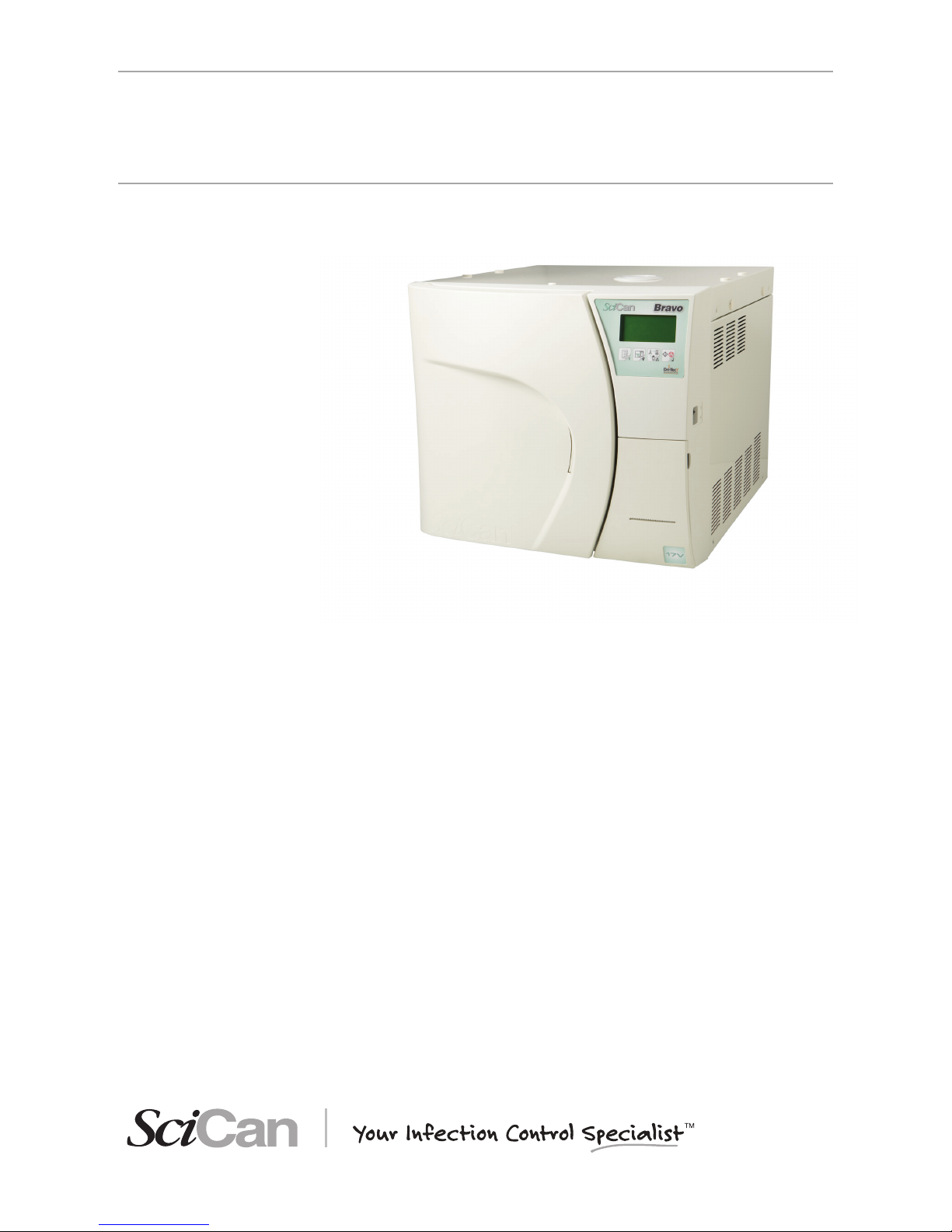
Congratulations on your selection of the Bravo™ Autoclave. We are con dent that you have
purchased the nest equipment of its type. The Bravo is a counter-top unit that features a
number of sterilizing cycles designed to meet your needs and suitability for steam sterilization.
The details of installing, operating and maintaining your Bravo are all contained within this
operator’s manual. To ensure years of safe, trouble-free service please read these instructions
before operating this unit and keep them for future reference. Operational, maintenance and
replacement instructions should be followed for the product to perform as designed. Contents
of this manual are subject to change without notice to re ect changes and improvements to the
Bravo product.
NOTE
this symbol indiCates important information.
WARNING
THIS SYMBOL INDICATES A POTENTIAL DANGER OF INJURY. FOLLOW THE PROCEDURES DESCRIBED IN THE MANUAL TO AVOID INJURING THE USER AND/OR
OTHERS.
DANGER
THIS SYMBOL INDICATES A POTENTIAL DANGER OF PROPERTY DAMAGE. FOLLOWS THE INSTRUCTIONS IN THE MANUAL TO PREVENT POTENTIAL DAMAGE TO
MATERIALS, EQUIPMENT OR OTHER PROPERTY.
DANGER
THIS SYMBOL INDICATES A POTENTIAL DANGER DUE TO HIGH TEMPERATURE.
THE MATERIAL THE STERILIZER IS COMPOSED OF MUST BE DISPOSED ACCORDING TO THE DIRECTIVE 2002/96/CEE.
Potenzial hazard due to high temperature.
Equipment in accordance with applicable directives.
Symbol for disposal in accordante with Directive 2002/95 EC, 2002/96/ EC,
and 2003/108/ EC.
Consult the user manual.
The Bravo units described in this manual are to be used exclusively for the sterilization of solid
and hollow re-usable instruments and porous materials (e.g., textiles).
WARNING
THE DEVICE MUST ONLY BE USED BY QUALIFIED PERSONNEL. IT MAY
NOT BE USED OR HANDLED BY INEXPERT AND/OR UNAUTHORIZED
PERSONNEL FOR ANY REASON.
THIS DEVICE MUST NOT BE USED FOR THE STERILIZATION OF FLUIDS,
LIQUIDS OR PHARMACEUTICAL PRODUCTS.
Do not permit any person other than certi ed personnel to supply parts for, service or maintain
your Bravo. SciCan shall not be liable for incidental, special or consequential damages caused by
any maintenance or services performed on the Bravo by a third party, or for the use of equipment
or parts manufactured by a third party, including lost pro ts, any commercial loss, economic
loss, or loss arising from personal injury.
Never remove the cover of the unit and never insert objects through holes or openings in the
cabinetry. Doing so may damage the unit and / or pose a hazard to the operator.
All elements of this book are common to Bravo17, Bravo17V and Bravo21V, except where noted.
DISCLAIMERS
SYMBOLS ON
EQUIPMENT
SYMBOLS USED
IN THE MANUAL
INTRODUCTION
Page 6
2
Please observe the following precautions in order to avoid injury or property damage:
– Use ONLY distilled water of high quality.
WARNING
THE USE OF WATER OF INADEQUATE QUALITY CAN SEVERELY DAMAGE
THE DEVICE.
SEE APPENDIX A, TECHNICAL CHARACTERISTICS IN THIS REGARD.
– Do not pour water or other liquids on the device;
– Do not pour inammable substances on the device;
– Do not use the device in the presence of gas or explosive or inammable vapors;
– Before performing any maintenance or cleaning, ALWAYS DISCONNECT the electricity.
WARNING
WHENEVER IT IS NOT POSSIBLE TO DISCONNECT THE ELECTRICITY TO
THE DEVICE, OR IF THE EXTERNAL POWER GRID SWITCH IS FAR AWAY
OR, AT ANY RATE, NOT VISIBLE TO THE MAINTAINER, PLACE A WORK
IN PROGRESS SIGN ON THE EXTERNAL POWER GRID SWITCH AFTER
TURNING IT OFF .
– Make sure the electrical system is grounded conforming to current laws and/or standards;
– Do not remove any label or nameplate from the device; request new ones, if necessary;
– Use only original replacement parts.
WARNING
THE FAILURE TO OBSERVE THE ABOVE, RELEASES THE MANUFACTURER FROM ALL LIABILITY.
GENERAL WARNINGS
Page 7
3
2
3
4
6
8
11
12
14 - 15
13
10
7
5
1
9
16
17
18
19
B
A
C
NOTE
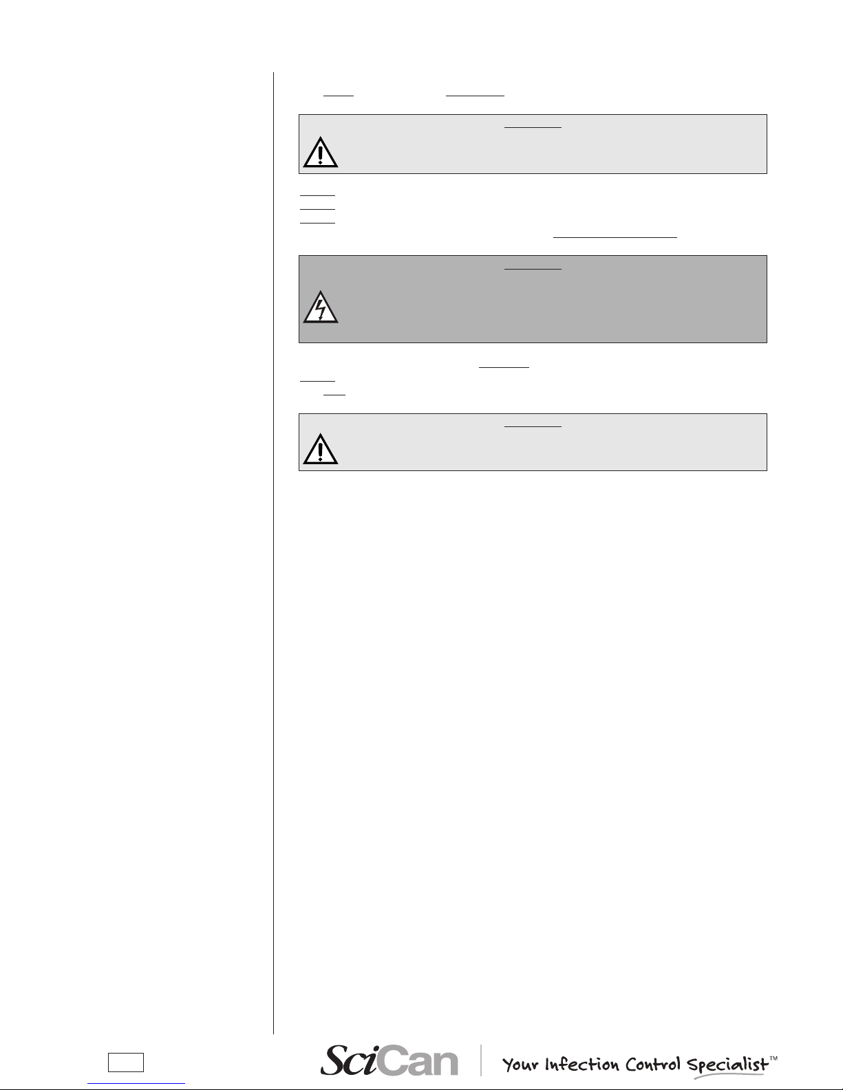
CheCk the integrity of the paCkage upon
reCeipt.
Once the package is opened, check that:
– the content matches the specications of the order
(see the accompanying document);
– that there is no obvious product damage;
Dimensions and weight 17 and 17V 21V
A. Height 600 mm 600 mm
B. Width 580 mm 580 mm
C. Depth 700 mm 800 mm
Total weight 62 kg 68 kg
NOTE
if you have reCeived the wrong produCt, are missing parts, or if your unit has any
type of damage, immediately provide a detailed desCription to the seller and shipper.
In addition to the steriliser, the package contains:
1. No. 3 stainless steel wire instrument tray
(BRAVO 17 includes 3 trays, BRAVO 17V/21V includes 5 trays);
2. Stainless steel wire tray support;
3. Operating documentation (with CD-ROM);
4. USB key for data storage;
5. Exhaust lter;
6. Tray extractor;
7. Water lling funnel;
8. Extra bacteriological lter;
9. Rubber hose with quick-coupling for manual water drainage;
10. 4 rubber caps;
11. 1/8” angular tting;
12. Spare roll of printer paper (optional);
13. Plastic tube with tting (automatic lling);
14. Allen wrench (3mm for rear cap removal);
15. Allen wrench (5mm for handle removal);
16. Plastic tube for direct water drainage with fastening clamp;
17. Bottle for manual lling;
18. No. 2 spacers;
19. Syringe.
NOTE
the Customer must keep the purChase reCeipt for any warranty serviCe.
DIMENSIONS
AND WEIGHT
DESCRIPTION OF
THE CONTENTS
CONTENTS OF
THE PACKAGE
Page 8
4
Where possible, the packaged product must be handled using suitable mechanical means
(forklift truck, transpallet, etc.) and following the instructions shown on the package.
In the case of manual handling, the product must be lifted by two persons using the handles cut
in the side of the box.
Once taken out of the box, the sterilizer must be lifted by two persons and transported on a lift
truck or similar means.
WARNING
WE RECOMMEND THAT THE DEVICE BE TRANSPORTED AND STORED
AT A TEMPERATURE NO LOWER THAN 5 °C. PROLONGED EXPOSURE TO
LOW TEMPERATURE AN DAMAGE THE PRODUCT.
NOTE
keep the original paCkaging and use it whenever the deviCe is to be transported. the
use of different paCkaging Could damage the produCt during shipment.
DANGER
BEFORE TRANSPORT, LEAVE THE DEVICE TURNED-OFF FOR ABOUT 30
MINUTES AFTER THE LAST PROGRAM FINISHES AND DRAIN THE DISTILLED WATER AND USED WATER TANKS SO THAT THE ALL THE HOT INTERNAL PARTS WILL HAVE TIME TO COOL.
HANDLING THE
PRODUCT
CAP REMOVAL
FROM THE TANK
BREATHER HOLE
(IF NECESSARY)
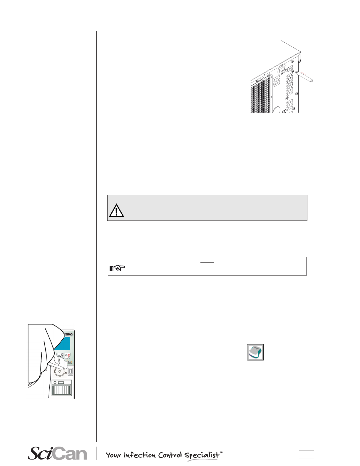
There may be a cap on the breather hole. If
present, the protection cap must ALWAYS
be removed from the breather hole of the
distilled water tank before starting the
sterilizer.
Use the Allen wrench provided with the
device and follow the procedure shown in
the gure.
WARNING
FAILURE TO REMOVE THE CAP MAY CAUSE THE DEVICE NOT TO WORK
PROPERLY AND ITS INTERIOR COMPONENTS BEING DAMAGED.
MAKE SURE YOU FOLLOW THE PROCEDURE DESCRIBED ABOVE BEFORE INSTALLING THE DEVICE.
Page 9
5
Bravo is SciCan's revolutionary chamber autoclave designed with safety, performance, exibility
and ease of use in mind.
It is a sophisticated yet easy-to-use sterilizer with a wide range of conguration options and
patented operating devices designed to satisfy every need for sterilizing medical and dental
tools, guaranteeing the maximum performance under all conditions.
Easy-to-use, compact and aesthetically pleasing, Bravo is the ideal partner for professionals
seeking maximum sterilization safety.
PRODUCT
OVERVIEW
GENERAL
CHARACTERISTICS
Bravo is a microprocessor-controlled steam sterilizer with a large sterilization chamber made of
stamped stainless steel.
It is characterized by an advanced fractionated vacuum system for the complete removal of
air from hollow and porous materials, and an effective nal vacuum drying phase capable of
effective drying of these loads.
Its exclusive steam generation system, effective plumbing circuit and electronic management
(supplemented by high-precision sensors) guarantees high process execution speeds and
excellent thermodynamic parameter stability. Moreover, its Process Evaluation System
constantly monitors all the machine's vital parameters in real-time, guaranteeing absolute safety
and perfect results.
It offers users 10 sterilization programs (one customizable), each equipped with optimized drying
for the fast, effective sterilization of the various types of loads (instruments and materials) used
in a medical or dental environment. The custom programs have not been validated and have not
been cleared in the U.S. by FDA for healthcare use.
Bravo units also offer a number of interesting options for conguring the preheating mode (based
on the sterilizer's frequency of use) and printing the cycle report (printer optional on Bravo17).
Bravo sterilizers also have one of the most complete, sophisticated and advanced safety systems
available today to protect users in the case of electrical, mechanical, or thermal operating
anomaly.
NOTE
please refer to appendex a (teChniCal CharaCteristiCs) for a desCription of bravo's
unintegrated safety deviCes.
Page 10
6
FRONT
LCD display and control panel
Sterilization chamber
Door
Door microswitch
Service compartment
access panel
Bacteriological lter
Printer paper output
slot
USB port
Exhaust lter
Encased printer (optional)
Service compartment
open
On/Off switch
Motorized closing system
Used water drain quick connector
Distilled water ll quick connect
Door
Distilled water tank drain quickcoupling
(SERVICE only)
Page 11
7
REAR
Distilled water tank
vent hole
Heat exchanger
Safety valve
Connection for automatic loading of the
load tank
Connection for directly draining the
used water tank
Band heating element safety thermostat and
manual rearm
Power cord
Steam generator safety thermostat
and manual rearm
Mains fuses
Version with automatic
loading with pump
Page 12
8
-
+
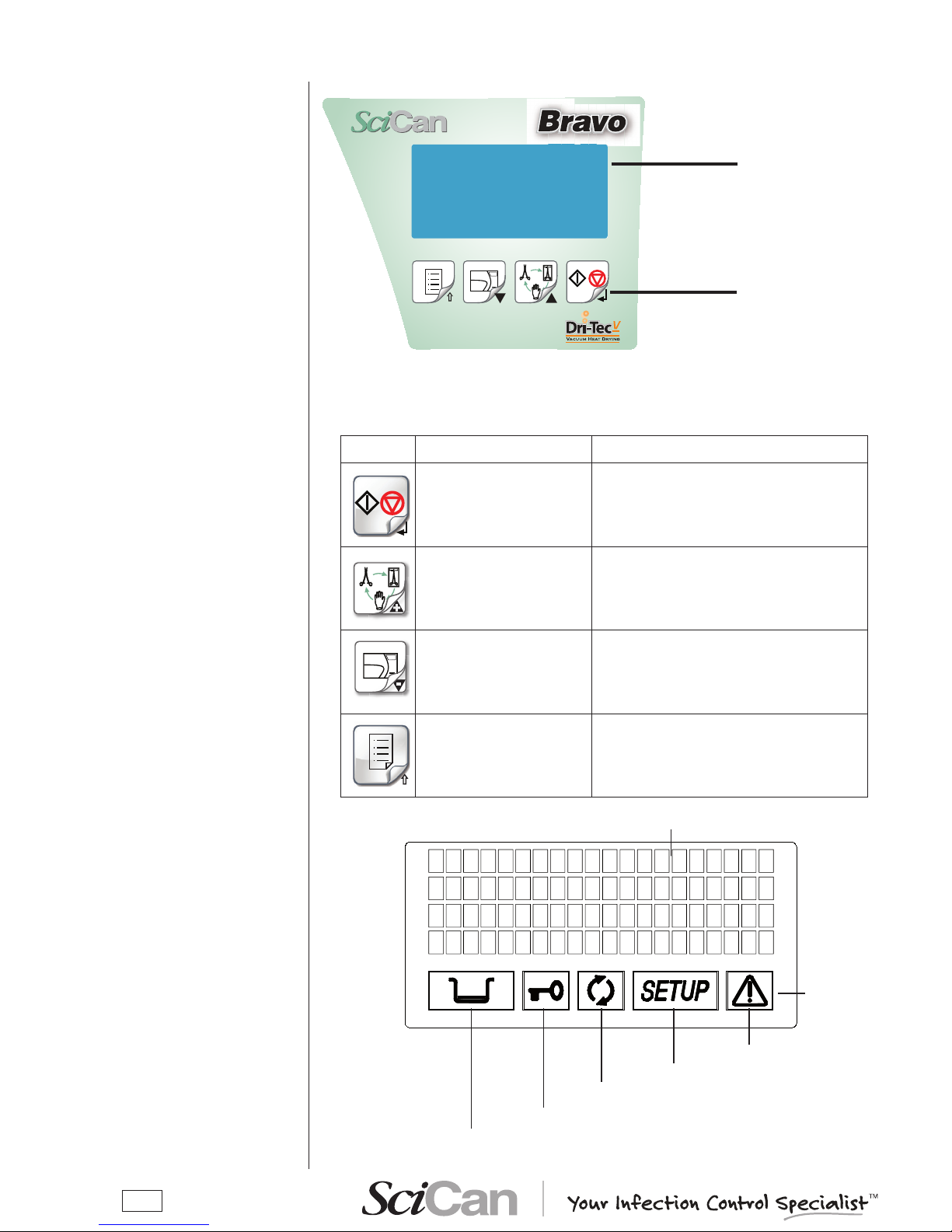
CONTROL PANEL
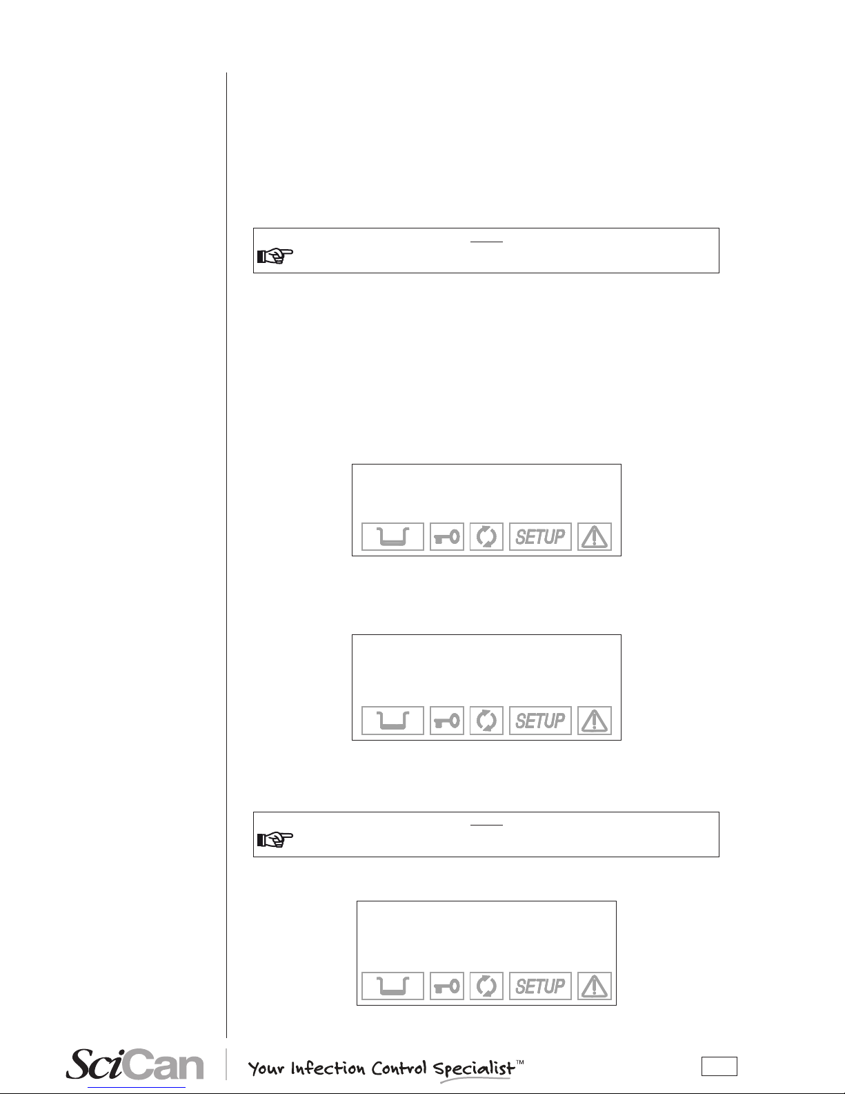
LCD DISPLAY
Liquid Crystal Display
(LCD)
Command keys
The function of the command keys differ according to operating mode of the equipment.
Key NORMAL mode SETUP mode
Cycle Start/Stop
Enter, con rmation of the value/option selected
+
+
+
Sterilization cycle selection
Value increment / Forward scroll of the
menu options
-
-
-
Test cycle selection
Value decrement / Backward scroll of the
menu options
Enter Setup mode ESC, quit the current menu
Alarm
Setup status
Process status
Port status
Water level
4 lines of 20 characters
Illuminated icon
Page 13
9
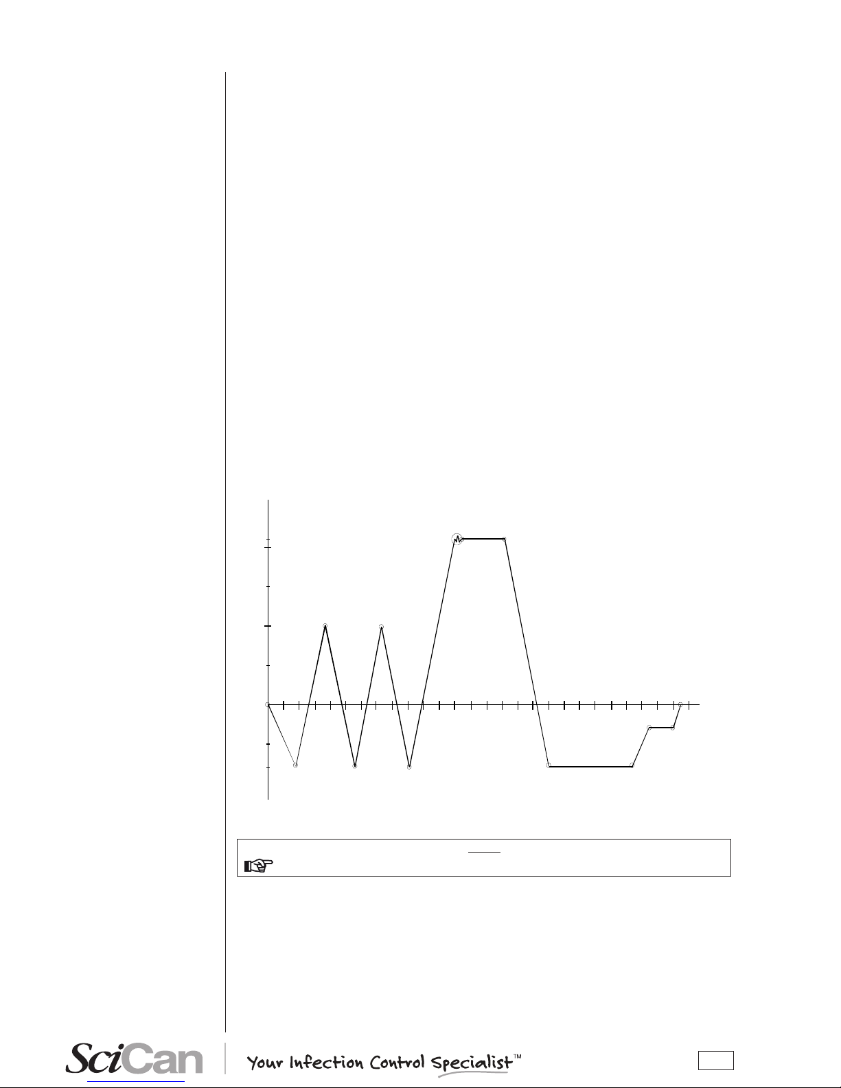
The Bravo’s sterilization program is a succession of phases, each with a specic purpose.
After loading the material in the chamber, closing the door, selecting the program and starting
the cycle (the door opening mechanism locks automatically), the standard program (for porous
materials, 134 °C at 4 minutes, for example) uses the following sequence:
1. Preheats the generator and sterilization chamber;
2. Removes the air and penetrates the material by steam through a series of vacuum
(extracting uid from the sterilization chamber) and pressure (injecting steam into the
chamber) phases;
3. Raises the pressure, with the consequent increase in the temperature of the steam,
until reaching the conditions required for sterilization (for example, 134 °C);
4. Stabilizes the pressure and temperature;
5. Sterilizes for the required time (for example, 4 minutes);
6. Depressurizes the sterilization chamber;
7. Begins vacuum-drying phase;
8. Ventilates the load with sterile air;
9. Brings the pressure of the sterilization chamber back to the atmospheric level.
After reaching atmospheric pressure, the door is automatically unlocked and can be opened to
remove the load from the sterilization chamber.
Phases 1, 3, 4, 6 and 9 are identical in all cycles, with slight variations of duration that are solely
dependent on the quantity and consistency of the load and the heating conditions of the sterilizer. Phases 2, 5, 7 and 8, however, vary their conguration and/or duration on the basis of the
cycle selected (and, consequently, the type of load) and the choices made by the user.
NOTE
please refer to appendix b (programs) for more detail.
SAMPLE OPERATING
CYCLE
0.00
1.00
2.00
2.10
Pressure (bar)
Time (
min)
VACUUM DRYING
PROC ESS
SINGLE VACUUM PULSE
-0.80
Page 14
10
A
C
B
C
B
A
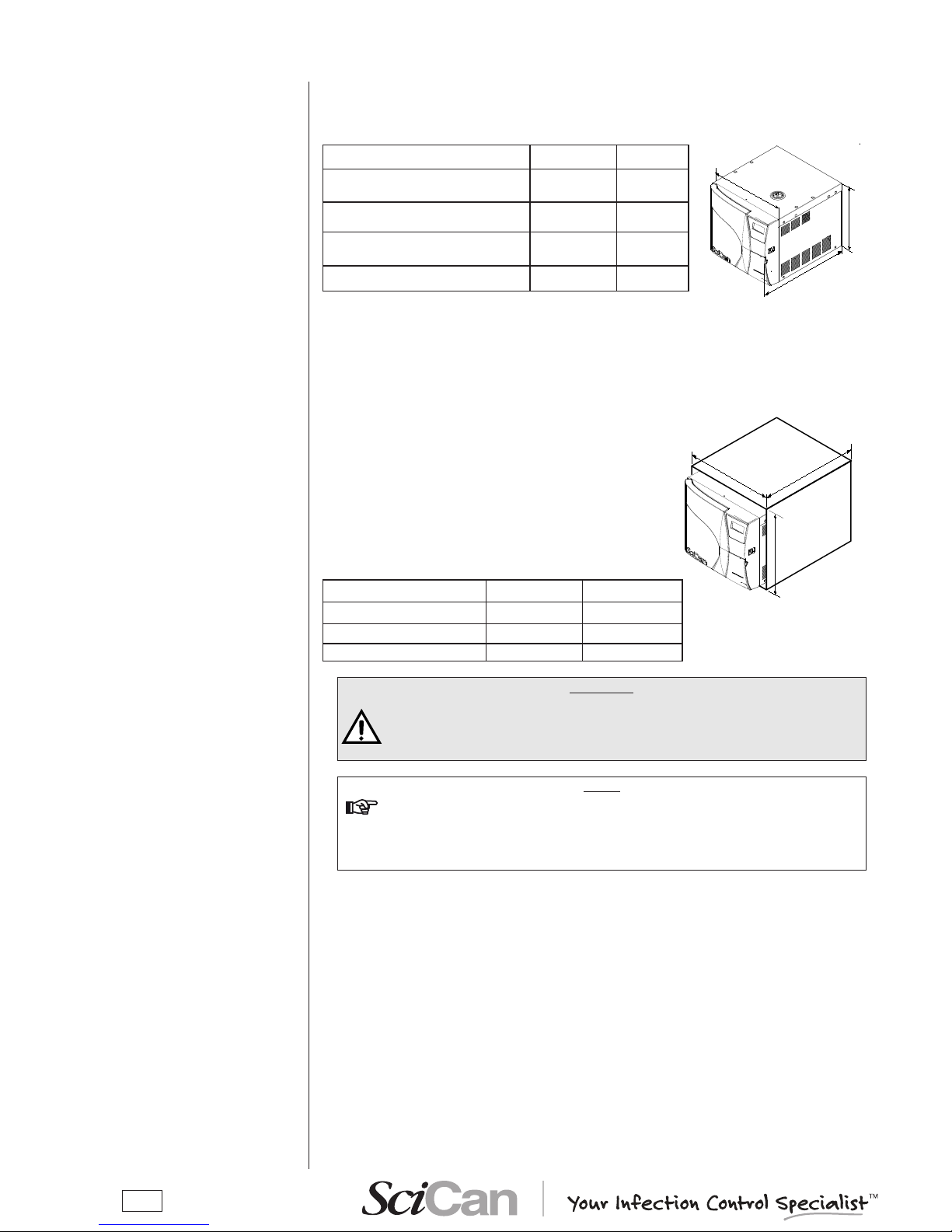
Correct and careful installation will ensure your Bravo functions properly, protects operators
from physical injury and protects property from damage.
Dimensions and weight 17 and 17V 21V
A. Height (total, excluding
handles)
420 mm /
16.5"
420 mm /
16.5"
B. Width (total)
480 mm /
19"
480 mm /
19"
C. Depth (excluding rear connections)
560 mm /
22.0"
660 mm /
25.0"
Total weight
58 kg / 128
lbs
63 kg /
139 lbs
Electricity
The electrical system to which the sterilizer will be connected must accommodate the electrical
characteristics of this device. This information is shown on the back of the machine.
When installing the sterilizer inside a cabinet, you must
provide adequate space all around the device to provide
effective ventilation. There should also be an opening in
the back large enough to provide adequate air ow. This
will allow optimum cooling of the heat exchanger.
A built-in compartment MUST have the minimum
dimensions shown in the gure at right.
Dimensions and weight 17 and 17V 21V
A. Height (total) 500 mm / 20" 500 mm / 20"
B. Width (total) 600 mm / 24" 600 mm / 24"
C. Depth 600 mm / 24" 700 mm / 28"
WARNING
COMPARTMENT DIMENSIONS LESS THAN THOSE SHOWN MAY
COMPROMISE THE CORRECT CIRCULATION OF AIR AROUND THE DEVICE
AND MAY NOT PROVIDE ADEQUATE COOLING. THIS CAN RESULT IN THE
DETERIORATION OF PERFORMANCE AND/OR POSSIBLE DAMAGE.
NOTE
do not remove the upper Cover or any other external part. when installed in
the Compartment, the deviCe must be Complete with all its parts.
please refer to appendix a (teChniCal CharaCteristiCs) for Complete teChniCal
data.
INSTALLATION
INTRODUCTION
COMPARTMENT
DIMENSIONS
FOR BUILT-IN
INSTALLATIONS
Page 15
11
To ensure operator safety and the correct performance of the device:
GENERAL
INSTALLATION
PRECAUTIONS
ELECTRICAL
CONNECTIONS
CONNECTION OF
USB PEN DRIVE
RECORDING DEVICE
– Install the sterilizer on a at level surface strong enough
to support the device's weight, and use the leveling feet to
compensate for an irregular surface;
– Leave adequate space for ventilation, at least 2" (50 mm) on
both sides and top and 4" (100 mm) at the back, using the
spacers supplied in the toolkit. If the device is installed in a
cabinet, be sure to respect the warnings in the preceding
paragraph, avoiding any obstructions to the air intake;
– Avoid contact with liquids. Do not install the sterilizer near
tubs, sinks or similar places, as this could cause short circuits
and/or potentially dangerous situations for the operator;
– Do not install the sterilizer in a place that is excessively humid or poorly ventilated;
– Do not install the machine were there is gas or ammable and/or explosive vapors;
– Install the device so that the power cord is not sharply bent or kinked. It must run freely to the
electrical connection socket;
– Install the device so that any external ll/drain tubing(s) is/are not sharply bent or kinked.
These must run freely to the drain tank.
The Bravo must be connected to an outlet that provides adequate capacity for the device's
absorption and ground, and which conforms with current laws and/or standards. The outlet must
also be protected by suitable breaker.
WARNING
THE MANUFACTURER WILL NOT BE LIABLE FOR DAMAGES CAUSED BY
INSTALLING THE STERILIZER ON AN INADEQUATE ELECTRICAL SYSTEM
AND/OR NOT EQUIPPED WITH A GROUND.
If it is necessary to replace the plug on the power cord, use one with equal characteristics or,
at any rate, adequate to the device's electrical characteristics. The user is entirely responsible
for the selection and replacement of the plug. This replacement should only be performed by a
trained service professional.
NOTE
always ConneCt the power Cord direCtly to the soCket. do not use extension
Cords, adapters or other aCCessories.
The recorded DATA can be copied, read and printed using DataFlash software installed on a
compatible personal computer that is tted with a USB port.
Installation of the DataFlash software stored on the CD-rom and attached to the operating
documentation.
– Insert the cd-rom into the CD drive of the PC.
– Click on “setup_DataFlash [rev]”.
– Follow the installation instructions that appear on the display. During installation, a "DataFlash"
folder is created which contains the necessary les.
– In addition, a programme icon is created on the PC's desktop.
Page 16
12
DataFlash software is a programme for Windows (versions 98, XP, and Vista) that allows users to
download data contained in the USB key to the PC and then and process that data.
Launch the DataFlash program from its desktop icon, or select the executable program
le.
After launching the program, a window appears containing the le reports folder (on the rst
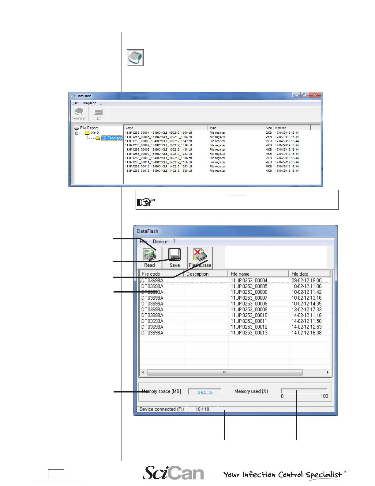
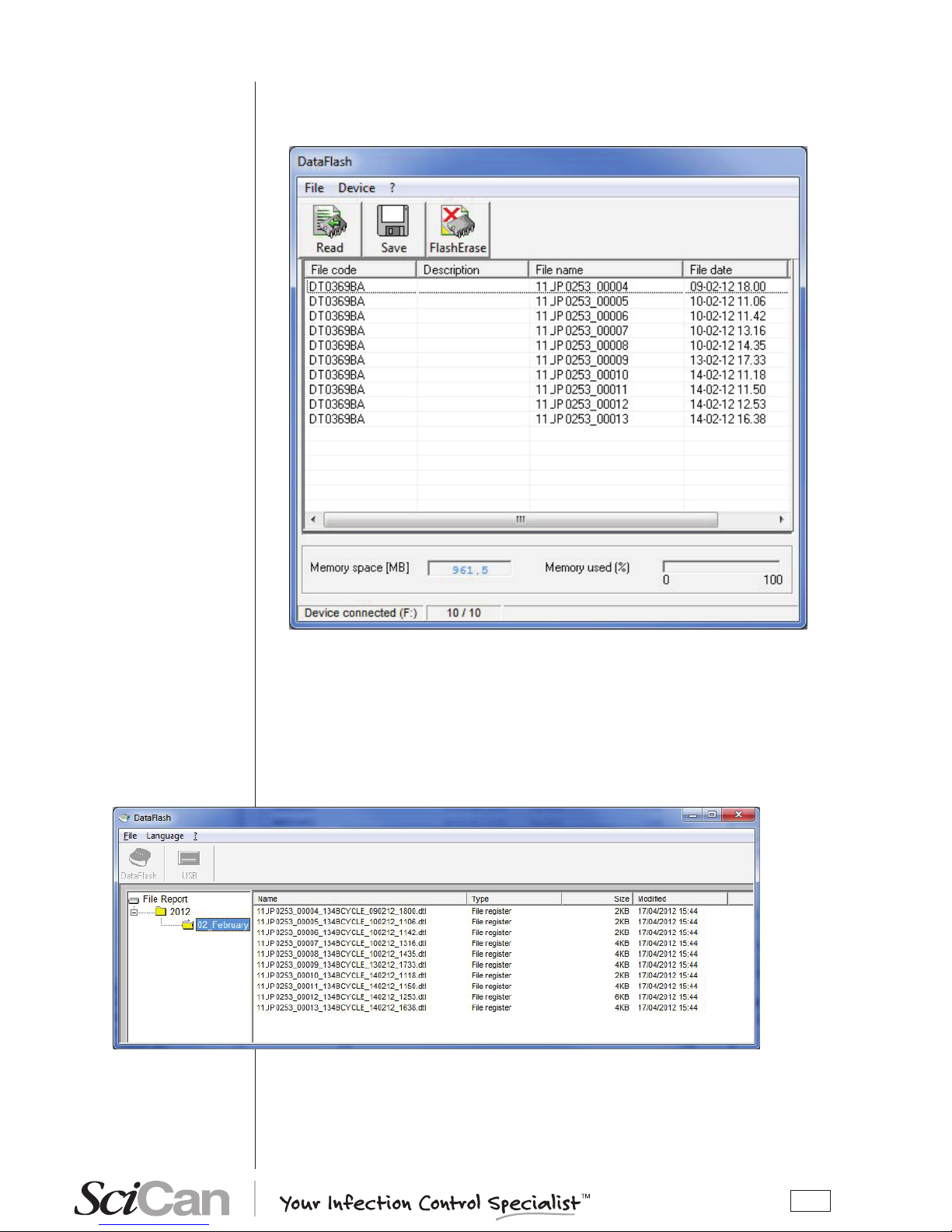
launch it will be empty). Click on the “USB” button to enable the connection to DataFlash.
note
the usb key must be ConneCted to the pC when the programme is started
otherwise an error message will appear.
A second window appears, containing the le list related to the stored sterilization cycles.
MANAGING THE FILES
BY DATAFLASH SW
Launching the program
Dialogue with the device
Reading of data
stored on the USB key
Saving the les on the
PC.
Cancellation of USB
key memory
List of stored les
Percentage of used me-
mory
NOTE: the keys functions are also present as sub-menus in the menu bar
Status bar
USB key storage
capacity
Page 17
13
Saving the Report fi le
Report fi le management
To save les stored on the USB key to the PC, select the Save key (or File-Save from menu).
The three keys and the window menu are disabled during the save process; the message “Ready” in the status bar shows is replaced by “Saving...”, followed by a number
and by a progress bar that shows the progress of the save process for the individual les.
At the end of the save process (status “Ready” and function keys enabled), close the window
for the dialogue with the device and proceed to the management of the les saved on the PC.
The les are saved according to the cycle date in a directory automatically generated by the
program and made up of folders for the years and subfolders for the months.
The les names are assigned on the basis of the cycle data, type, size and date of modi cation
of les are also included.
Page 18
14
The les saved on the PC are named “Mocom register”. Each new le is assigned a default
name according to the information included in the original le:
Es.: 12JM1234_00001_134PRION_190406_1024.dtl
File extension “.dtl”
(data logger)
Cycle start time
Cycle start date
Type of the cycle
Cycle counter (launched)
Sterilizer's serial number
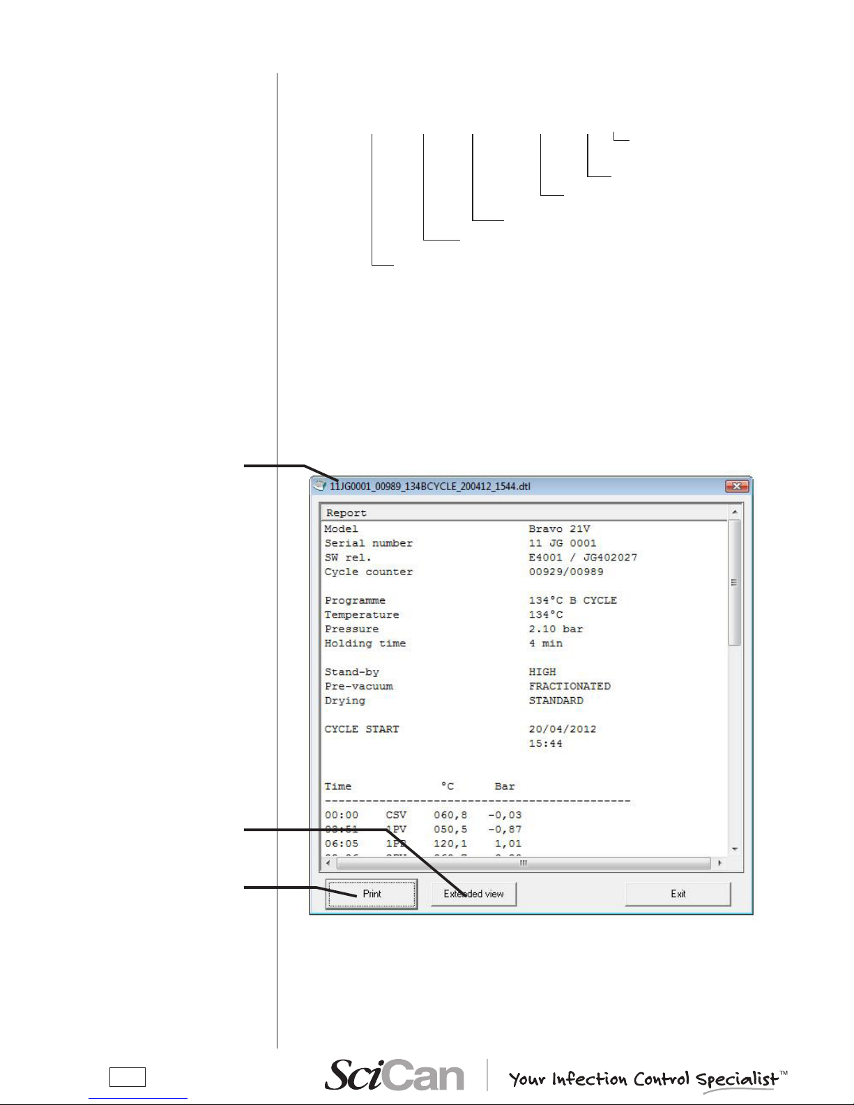
A double click on the le name, will show the window with the le content.
There are two types of visualization:
– reduced - default, shown on le opening;
– extended – click the “Extend view” button to see the details of the sterilization cycle, with all
data omitted in the reduced view.
If the cycle did not completed successfully, the view on opening is the extended one and the
reduced view cannot be selected.
To print the displayed le, connect a printer to the PC and click the “Print” button.
File name
Files visualization
File name
To print the le
Extended view
Page 19
15
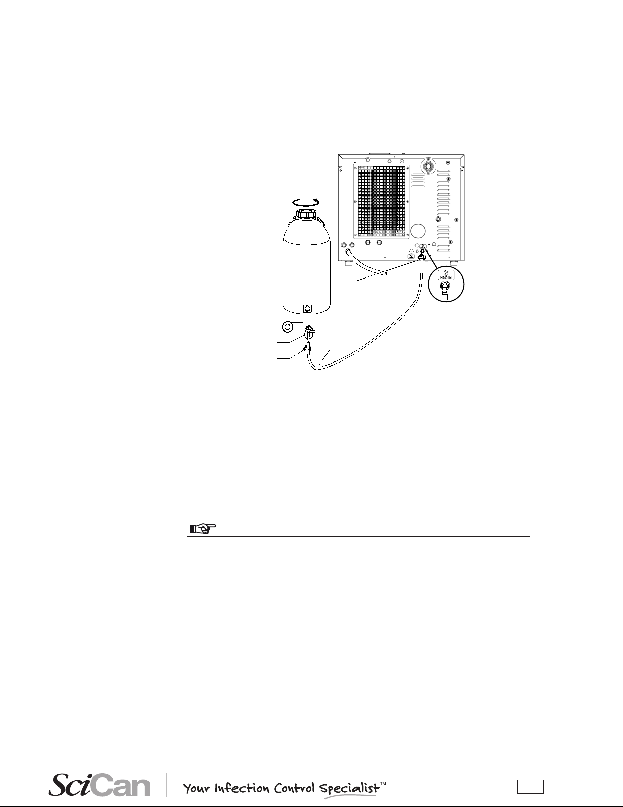
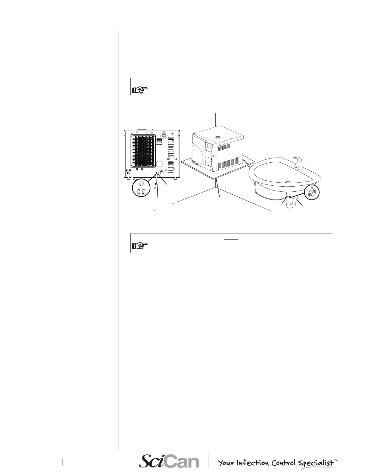
To avoid having to regularly ll the internal water tank (see Chapter 5 - Instructions for Use), it is
possible to connect the sterilizer to an optional external tank that the user will less frequently ll, or
to a commercially-available, water purication system with accumulation tank.
With this option, the autoclave automatically activates a pump that lls the internal tank when it
reaches the MIN level. Be sure to monitor the external tank as the Bravo unit can not monitor the
water level in the external tank.
To connect the external tank, follow the instructions below:
– Install the tap provided on the tank; use Teon tape or connector sealant for a perfect seal.
Clip
Silicon pipe
Teflon
Tap
Clip
Filling tank
– Use the tank’s silicone tube (or other suitable tube) and insert it on the lling connector taking
care to push it completely on.
– Lock the tube to connector with the plastic tie provided.
– Insert the other end of the tube on the tap of the tank.
– Make sure that the tube runs freely from the device to the tank, without being bent, crushed
or obstructed in any way.
– Loosen the cap to facilitate the ow of water.
– Open the tap on the lling tank.
NOTE
refer to the Chapter — Configuring the deviCe - automatiC filling option.
CONNECTING AN
EXTERNAL WATER
FILLING TANK
(OPTIONAL, automatic filling
function)
Page 20
16
Follow the instructions shown below for a correct direct connection to a centralized draining
point:
– Insert the silicone tube (provided) or other suitable plastic tube onto hose connection A; push
the tube all the way on and lock with the plastic tie or other means;
– Cut the tube to measure, push the free end on the connection provided on the centralized
draining point and lock with the plastic tie or other means.
NOTE
make sure the tube is not bent, Crushed or obstruCted in any way.
The following diagram provides an indicative arrangement of the components:
NOTE
the ConneCtion point to the Central drain must be lower than the sterilizer's
support surfaCe. otherwise, the tank may not empty CorreCtly.
DIRECT CONNECTION
TO A CENTRALIZED
DRAINING POINT
Support
plane
Pipe
Connector (A)
This point must be at level
lower than the sterilizer's
support plane
To the centralized
draining point
Drain siphon
Clamp
Page 21
17
Once the sterilizer has been correctly installed, it may be turned on and prepared for use.
Turn on the equipment by the main switch located on the right side of the machine.
NOTE
do this with the sterilizer's door open
.
When turned on, the control panel lights up and beeps so you can visually check its correct
operation. The panel then displays this message:
Apparatus serial number
Firmware version
BRAVO 17V
R. Exxxx/ JPyyyyy
12 JP 0001
DEVICE CHECK-UP
NOTE
if the door is Closed, the test is interrupted. the panel then beeps and displays the
following message.
OPEN THE DOOR
TO CONTINUE
Open the door to allow the test to continue. At the end of the test you will see:
BRAVO 17V
R. Exxxx/ JPyyyyy
12 JP 0001
CHECK-UP COMPLETE
The sterilizer measures the ambient pressure for the correct operation of several auxiliary
devices. Whenever the difference between the value read and that previously stored (see the
Chapter 6 — Configuration Acquisition of the ambient pressure) is higher than a set value,
the system automatically updates the stored value after a brief delay. Otherwise, the data
remains unchanged without updating.
After updating, the device performs the initial automatic test procedure (see above). At the end,
the display shows the following message (accompanied by a beep).
AMBIENT PRESSURE
VALUE UPDATED
-0.01 bar
↵ to continue
When ↵ is pressed, the device goes to STAND-BY mode (see below).
FIRST START-UP
TURNING ON
THE EQUIPMENT
INITIAL AUTOMATIC
TEST
ACQUISITION
AND UPDATING
OF THE AMBIENT
PRESSURE VALUES
Page 22
18
After the initial test, the sterilizer goes to STAND-BY mode and the display shows:
Counter xxxxx/yyyyy
Stand-by HIGH
23.6 °c 30/08/12
-0.01 bar 18:13:05
The upper line is the cycle counter for sterilizations performed, with the number of correctly
completed cycles on the left and the total number started on the right. The line below shows
the Stand-by status and the preheating mode (High-Low-Off). The two lower lines show the
temperature and pressure of the sterilization chamber on the left and current date and time on
the right.
NOTE
a CyCle begins with the start of the sterilization CyCle (first vaCuum phase),
exCluding the preheating phase. a CyCle ends at the end of the program (see the
C
hapter — program exeCution).
t
o set the date and time as well as seleCt the preheating mode, print the data and
fill the tank, please refer to the Chapter, “Configuring the deviCe”.
At regular intervals, the rst two lines on the display alternate with the modes set for printing
(ON/OFF) and lling (Manual/Automatic):
Print ON
Filling MANUAL
23.6 °C 01/02/12
-0.01 bar 18:13:05
The icons in the lower part of the LCD screen remain off with the exception of the door status
and/or water level indicators, which light-up if the door is closed and/or the level in the lling tank
reaches its MIN or MAX values (or the MAX value in the drain tank).
During the rst start-up, the MIN water level icon in the ling tank is normally on.
The device waits for the selection of the desired sterilization program (see the Chapter —
Program Selection).
DANGER
WHEN THE DOOR IS OPEN IN STAND-BY MODE, A BEEP INDICATES
THAT THE SURFACES INSIDE THE DEVICE ARE HOT. TO AVOID
BURNS, TAKE CARE NOT TO TOUCH THE STERILIZATION CHAMBER,
THE SUPPORTS PROVIDED OR THE INSIDE OF THE DOOR WITH YOUR
BARE HANDS.
STAND-BY MODE
Page 23
19
The rst time the sterilizer is used, or when the MIN water level indicator comes on, you will have
to ll, or top-off, the internal distilled water tank.
Operate as follows (with the machine on) referring to the gure:
1. Remove the rubber cap.
2. Insert the lling funnel provided in the llercap.
3. Slowly pour the distilled water into the funnel until the
MIN icon
goes off.
4. Continue lling with water until reaching the maximum
level in the lling tank, indicated by the MAX icon
coming on accompanied by an acoustic war-
ning.
Immediately stop lling; under no circumstances exceed the MAX limit indicated at the
bottom of the llercap.
Be carefulnot to spill any water on the machine, and if so, immediately dry it off.
5. Remove the funnel from the llercap.
6. Ret the rubber cap.
With reference to the gure (and with the door open), follow these steps:
1. Fill the manual container (2 litres/ 0.52 US gal) with
distilled water, keeping it horizontal.
2. Connect the tube’s quick connector to the corresponding
female connector under the chamber entrance (marked
), pushing until you hear a click.
3. Place the container in a vertical position and loosen the
cap and taking care not to spill water on the machine.
4. The water will begin to ow into the tank.
5. Continue lling until the MIN level indicator turns off or
the MAX level indicator turns on.
6. At this point, lower the bottle below the connection
point on the unit, keeping it horizontal.
7. While pinching the tube with your ngers press the metal lever on the side of the connector and
detach the quick connector.
8. Rell the container (2 litres/ 0.52 US gal) and repeat steps 2, 3 and 4 a second time until the MAX
level icon appears on the display.
9. When the MAX level icon comes on (accompanied by a beep), stop lling and detach the quick
connector as described in steps 6 and 7.
NOTE
the iCon max does not have to be on to start a sterilization
program. there is suffiCient water if the min indiCator is off.
do not Continue to fill onCe max iCon appears and you hear a beep. doing so may
Cause water to drain from the unit's water tank draining point at the baCk of the
maChine.
FILLING DISTILLED
WATER
Manual filling (front side)
Manual filling (top side)
Page 24
20
Automatic filling
When the water level in the internal or external drain tank reaches the MAX level, the LCD display
alternatively lights the MAX and MIN icons.
NOTE
at this stage, the unit will generate an alarm indiCation (see appendix e - alarm)
should you attempt to start a sterilization CyCle.
In this case, empty the internal or external draining tank.
To drain the internal tank, follow these steps:
1. Arrange an empty container on the oor near the
sterilizer and put the free end of the supplied tube
into the container.
2. Connect the quick connector to the corresponding
female connector under the chamber entrance
(marked ) pushing until you hear a click.
3. Wait for the internal tank to drain completely,
then while pinching the tube with your ngers,
press the metal lever located on the side of the
connector and detach the quick connector.
MAX LEVEL IN THE
INTERNAL / EXTERNAL
DRAIN TANK
Emptying the used water
internal tank
Detaching the pipe
If a unit is set up for automatic lling from an external tank, the lling will occur automatically after
this automatic lling option has been selected.
NOTE
use only high quality distilled water. for the speCifiCations of the water supply,
see appendix a (teChniCal CharaCteristiCs).
To set the automatic lling option, please refer to the Chapter — Conguration – Setting the tank
lling mode.
WARNING
THE AUTOMATICALLY FILLING SYSTEM MUST NEVER RUN DRY;
THIS WILL CAUSE PREMATURE WEAR TO THE AUXILIARY WATERINJECTION PUMP. PERIODICALLY CHECK THE WATER LEVEL IN THE
EXTERNAL TANK.
IF AUXILIARY WATER-INJECTION PUMP RUNS DRY, THIS MAY BE AN
INDICATION OF AN EMPTY EXTERNAL WATER TANK, AND THE UNIT
WILL DISPLAY A CYCLE FAULT A040. TURN OFF THE POWER TO THE
UNIT AND FILL THE EXTERNAL BOTTLE WITH DISTILLED WATER. THEN
TURN THE UNIT POWER ON.
Page 25
21
-
+
Bravo users can con gure the device to meet their speci c needs. For example, the device's
performance may be adapted on the basis of the type of activity, the type of material to be
sterilized or its frequency of use.
The SETUP program allows selecting from several options that users can activate through an
easy-to-use menu.
NOTE
use the setup program whenever neCessary. a CorreCtly personalized deviCe
provides the best performanCe and the most satisfaCtory use.
s
CiCan Customer support (see appendix z) is available to help users by providing
suggestions or adviCe on the best way to uses the options in the setup program
To start the SETUP program, hold down the ⇑ key on the control panel for several seconds, until
the display shows:
BRAVO 17V
SETUP
↵ to continue
⇑ to exit
NOTE
iCon setup on the display lights-up and stays on or the entire Configuration
phase.
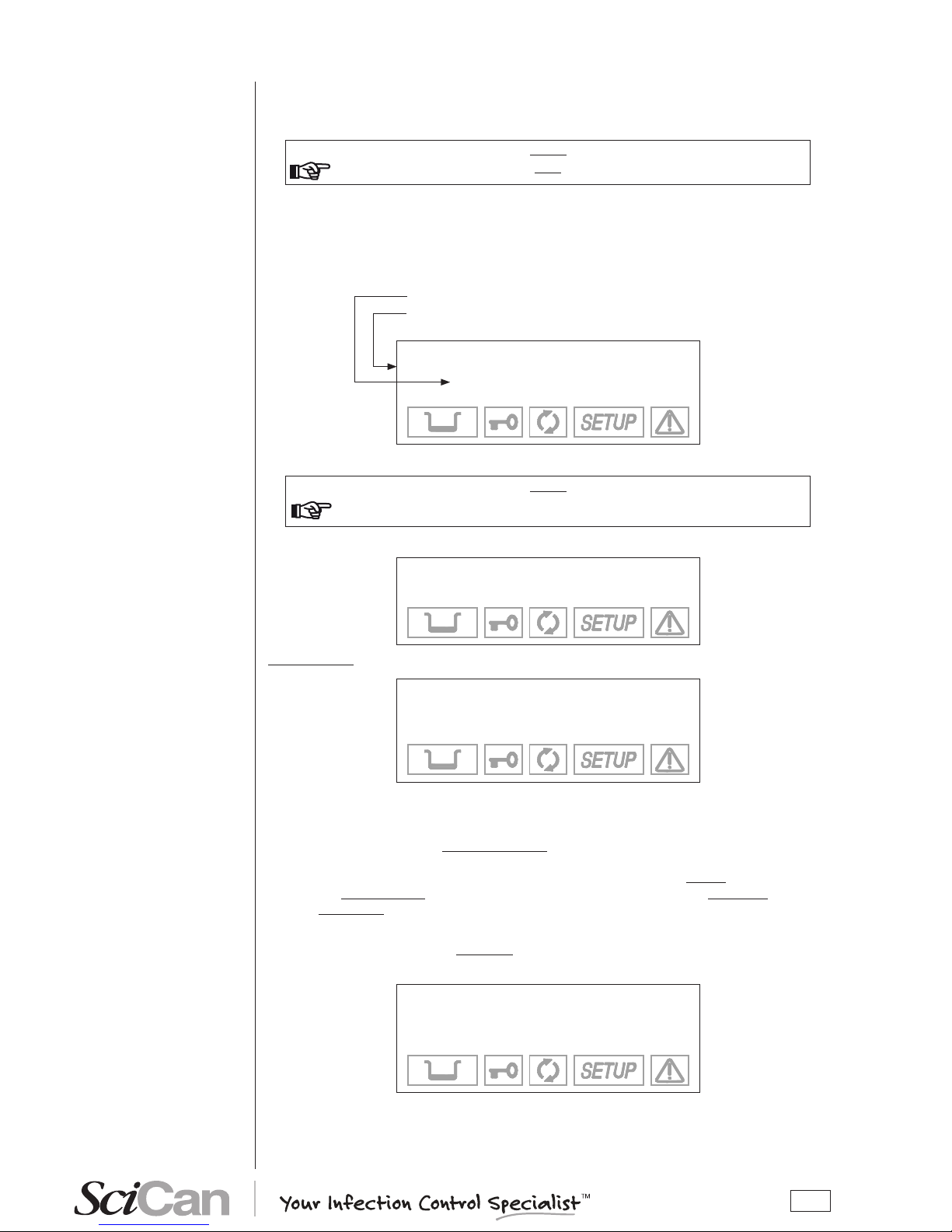
When you press the ↵ key, you enter the SETUP. The screen shows the rst-level menu items
(see the paragraph, SETUP fl owchart).
Press the ESC key ⇑ quits the SETUP program and takes you back to normal operation (standby mode).
NOTE
the setup program Can only be started in stand-by mode. it is not aCCessible
during sterilization or test CyCles.
In SETUP mode the control panel keys have different functions than in normal mode.
Key SETUP mode function
ENTER key to con rm the selected option or value
+
Increase the value /scroll up
-
-
-
Decrease the value /scroll down
ESC key to exit the selected menu option
Now, we describe the meaning of the various main menu and second-level menu items.
CONFIGURATION
INTRODUCTION
STARTING AND
ENTERING THE
SETUP MODE
MEANING OF THE
KEYS IN SETUP MODE
Page 26
22
Rev. 07 (de l 16/12/2005)
YES
BASIC
ADVANCED
dd/mm/yyyy
+/- to set
↵
to enter
⇑ to exit
hh:mm:ss
+/- to set
↵
to enter
⇑ to exit
LANGUAGE
DATE SETTING
TIME SETTING
EXIT
HIGH
LOW
OFF
EXIT
PRINT OPTIONS
STAND-BY OPTIO NS
PROGRAMS
FILLING OPTIONS
EXIT
EXTRA: XX min
+/- to set
↵
to enter
⇑ to exit
AUTOMATIC
MANUAL
EXIT
PRINTER
REPORT
EXIT
NORMAL PRINT
EXTENDED PRINT
EXIT
COPIES: XX
+/- to s
et
↵
to enter
⇑ to exit
NR. COPIES
PRINT LAST
EXIT
INTERNAL
EXTERNAL
EXIT
134c PROCESS
121c PROCESS
EXIT
TIME: XX min
+/- to set
↵
to enter
⇑ to exit
4th PRESET
3rd PRESET
2nd PRESET
EXIT
MILLENNIUM B
SETUP LAYOUT
NOTA
2nd LEVEL
MENU’
PRINT
REPORT
NOW PRINTING
THE REPORT
PLEA SE WA IT...
134 SOLID / WRAPPED
121 SOLID / WRAPPED
134 SOLID / WRAPPED
121 SOLID / WRAPPED
134 HOLLOW / UNWRAP.
121 HOLLOW / UNWRAP.
134 EMERGENCY
XXXc CUSTOM
EXIT
SHORT DRYING
LONG DRYING
EXIT
FRA CTIO N. V ACUUM
SINGLE VACUUM
EXIT
STANDARD DRY ING
INTELL. DRYING
EXTRA DRYING
EXIT
STANDARD DRY ING
FAST DRYING
EXIT
NO
SPECIAL
SERVICE
REVIEW
EXIT SETUP
PRESSURE VALU
E
SET INTO MEMO RY
WARNIN G!
OPEN THE DOOR
TO CONT INUE
Is the door
open?
EXIT SETUP (st-by)
or
RESUME SETUP
time
limited
(+ beep)
until door
opening
AMBIENT PRESSURE
EXIT
LCD CONTRAST
Selected progra m (see menu)
STND, I NTEL, EXTRA (long dry ing)
STND, F AST (short dry ing)
INTERNAL, EXTERNAL CR , EXTERNAL
CR+LF
MANUAL, AU TOMATIC (f illing)
INTERNAL, EXTERNAL (drain)
HIGH, LOW, OFF
30 min, … , 300 min (s
tep of 30 m in)
ESPANOL
DEUTSCH
EXIT
ITALIANO
ENGLISH
FRANCAIS
ST-BY TIMEOUT
ST-BY MODE
EXIT
TIMEOUT: XXX min
+/- to set
↵
to enter
⇑ to exit
CR TYPE
CR+LF TYPE
EXIT
TYPE 1
TYPE 2
EXIT
ACQUISI TION OF THE
AMBIEN T PRESSU RE
↵
to enter
⇑ to exit
ADJUSTMEN T OF THE
LCD C ONTRAST
+/- to set
⇑ to exit
1st PRESET
starting
from 01’
CONTINU E
-
(press +/ to scroll )
BRAVO 17V
EXIT SETUP?
↵
to conf irm
⇑ to res
ume
Firmware rele ase
Exxxx / JPyyy yyy
Serial Number
ENGLISH
Date
dd/mm/yyy y
Time
hh:mm:ss
1st PRESET
134 POROUS/WRAPPED
STANDARD DRYING
Stand-by option
HIGH
120 min
Print option
EXTERNAL CR+LF
1 copy
Filling option
AUTOMATIC
Drain option
INTERNAL
EXIT
REVIEW
↵ to confirm
2nd PRESET
134 HOLLOW/UNWRAP.
FAST DRYING
3rd PRESET
134 SOLID/WRAPPED
EXTRA DRYING (+05)
4th PRESET
134 SOLID/UNWRAP
FAST DRYING
DRAIN OPTIONS
INTERNAL
EXTERNAL
EX
IT
OFF
134 HOLLOW / UNWRAP.
+
121 HOLLOW / UNWRAP.
sample
visualization
BRAVO
SETUP
↵
to continue
⇑ to exit
ONLY AVAILABLE FOR
SCICAN SERVICE
3rd LEVEL
MENU’
TIME: XX min
+/- to set
↵
to enter
⇑ to exit
starting
from 18’
CR TYPE (+FF)
CR+LF TYPE (+FF)
EXIT
DISABLED
ANY CYCL E START
ANY POWER ON
PASSW ORD
INSERT PASSWORD
* * * * * * * * * * * * * * *
*
↵
to enter
CONFIRM PASSWORD
* * * * * * * * * * * * * * *
*
↵
to enter
PRINTOUT MODE
AT CYCLE END
STEP BY STEP
EXIT
Quando il comando EXIT è attivato si torna al menù
precedente (il tasto ESC sulla tastiera ha lo stesso eetto
del comando EXIT)
Quando un OPZIONE nale
è stata selezionata
(memorizzata) si torna al 2°-3° livello del menu.
BRAVO
Configuration menu diagram:
NOTES
When EXIT (EXIT) is selected, the previous menu
level is restored (the ESC key on the panel has the
same function as the EXIT (EXIT) key).
When the last menu OPTION available is selected
(or when recording is conrmed) the previous menu
level is restored.
Page 27

23
MAIN MENU
The main menu has 6 entries that open additional (second-level) menus:
BASIC (basic options)
ADVANCED (advanced options)
SPECIAL (special options)
SERVICE (menu not accessible to users)
DATA REVIEW (summary of options selected)
EXIT SETUP (exit the SETUP program and return to normal operation. In this
regard, see the paragraph, Exiting the SETUP program)
BASIC Menu
The Basic menu (basic options) consists of the items:
LANGUAGE (language setting)
DATE SETTING (setting the current date)
TIME SETTING (setting the current time)
PASSWORD (setting the password)
EXIT (exit the BASIC menu and return to the main menu)
ADVANCED Menu
The Advanced menu (advanced options) consists of the items:
PROGRAMMES (setting preselected sterilization programs, shown on the LCD
display)
STAND-BY OPTIONS (stand-by mode settings)
PRINT OPTIONS (setting printer and printing options)
FILLING OPTIONS (setting modes for filling the distilled water tank)
DRAIN OPTIONS (setting the modes for emptying the used water tank)
EXIT (exit the ADVANCED menu and return to the main menu)
SPECIAL Menu
The Special menu (special options) consists of the following items:
AMBIENT PRESSURE (acquisition of the ambient pressure)
LCD CONTRAST (adjusting the contrast of the Liquid Crystal Display)
EXIT (exit he SPECIAL menu and return to the main menu)
SERVICE Menu
The Service menu can ONLY be accessed by the Service department.
DATA REVIEW Menu
The Data Review displays a summary of the device's current settings, allowing users to verify
their correctness.
DESCRIPTION OF
THE MENU ITEMS
Page 28
24
It has the following screens (shown by way of example):
BRAVO 17V
R.Exxxx/JPyyyyyy
10 JP 0001
ENGLISH
DATE
dd/mm/yyyy
TIME
hh:mm:ss
Use the keys
+ / - to scroll through the menu
1st PRESET
134 POROUS/WRAPPED
STANDARD DRYING
2nd PRESET
134 HOLLOW/UNWRAP.
FAST DRYING
Use the keys + / - to scroll through the menu
3rd PRESET
134 SOLID/WRAPPED
EXTRA DRYING + 05
4th PRESET
134 EMERGENCY
FAST DRYING
Use the keys + / - to scroll through the menu
Stand-by option
HIGH
120 min
Print option
OFF
1 copy (ies)
Use the keys + / - to scroll through the menu
Filling option
AUTOMATIC
Drain option
INTERNAL
Use the keys + / - to scroll through the menu
EXIT
DATA REVIEW
↵ to continue
Press ↵ to continue
NOTE
to learn more about any of the terms above, see Chapter — aCtivating -
C
onfiguration options.
Page 29
25
The sterilizer leaves the factory with the following settings:
DATE: current date
TIME: current time
PROGRAMS: 1° PRESET: 134°C POROUS/WRAPPED
2nd PRESET: 121°C HOLLOW/UNWRAP
3rd PRESET: 134°C SOLID/WRAPPED
4th PRESET: 134°C SOLID/UNWRAP
NOTE
the programs indiCated should be Considered as preferential settings. however,
other Combinations are possible based on the destination market.
ST-BY MODE: HIGH (preheating)
PRINT OPTIONS: INTERNAL (1 copy, with optional printer)
FILLING OPTIONS: MANUAL
DRAIN OPTIONS: INTERNAL
To congure the unit access the SETUP mode from the stand-by screen, enter the SETUP mode
by holding down the ⇑ key on the control panel for several seconds until the SETUP screen
appears (shown below).
Counter xxxx/yyyy
Stand-by HIGH
23.6 °C 30/08/02
-0.01 bar 18:13:05
Scroll to the BASIC menu and press the ↵ key. From here, scroll and select any of the following
conguration options.
Select LANGUAGE using the ↵ key. The following screen will appear:
→ ITALIANO +
ENGLISH ↑
FRANÇAIS ↓
DEUTSCH ESPAÑOL
Select the desired language.
Move using the + or – keys and conrm using the
↵ key to store the selection. After the data is
conrmed, you return to the second-level menu.
NOTE
as soon as the seleCtion is Confirmed, all the menus of the setup program will
be displayed in the language set.
When DATE SETTING is selected with the ↵ key, you will see:
dd/mm/yyyy
+/- to set
↵ to enter
⇑ to exit
DEFAULTS SETTINGS
ACTIVATING
CONFIGURATION
OPTIONS
Setting the language
(LANGUAGE on the BASIC
Menu)
Setting the date
DATE SETTING on the BASIC
Menu)
Page 30

26
To set the date, follow these steps:
– When the day ashes: set the current date with the + and - keys. Conrm with ↵.
– When the month ashes: set the current month with the + and - keys. Conrm with ↵.
– When the year ashes: set the current year with the + and - keys. Conrm with ↵.
The date is stored. Once the last conrmation is given, you return to the second-level menu.
When TIME SETTING is selected with the ↵ key, you will see:
hh:mm:ss
+/- to set
↵ to enter
⇑ to exit
Follow these steps:
– When the hours ash: set the current hour with the + and - keys. Conrm with ↵.
– When the minutes ash: set the current value with the + and - keys. Conrm with ↵.
When the last conrmation is given, return to the second-level menu.
When PASSWORD is selected with the ↵ key, you will see this menu:
→ DISABLED +
ANY POWER ON ↑
ANY CYCLE START ↓
EXIT -
Select DISABLED to use the device freely, without any limitation on operator access.
Select ANY POWER-ON to password protect the main power switch. This allows only authorized
personnel to turn the unit on. Once it is on, it can be used by any operator.
Select ANY CYCLE START to password protect the unit both at power-on and at the start of
every sterilization program. In this mode, only authorized personnel will be able to use it.
NOTE
entering a password provides more Controlled use of the produCt but, at the same
time, inevitably makes it more Cumbersome. so as not to overly CompliCate using the
deviCe, we reCommend only aCtivating this option when it is really needed.
When the ANY POWER-ON or ANY CYCLE START options are selected, the following screen
is displayed:
INSERT PASSWORD
↵ to enter
⇑ to exit
Enter the password with the + and – keys (xed length, 8 characters).
Conrm with the ↵ key. Then, the following message will appear:
CONFIRM PASSWORD
↵ to enter
⇑ to exit
Enter the password again using the + and – keys. Conrm with the ↵.key
Setting the time
(TIME SETTING on the BASIC
menu)
Setting the password
(PASSWORD on the BASIC
menu)
Page 31

27
NOTE
to Change the password, first seleCt the disable option, whiCh CanCels the pre
-
vious password, and then seleCt the any power-on or any CyCle start
option, entering the new password as desCribed above.
Setting and storing customized sterilization programs in the four pre-set positions can be
completed by following these steps, starting in the advanced menu.
Each pre-set position can be associated to a standard or user congurable cycle (CUSTOM).
To associate a standard program and dene several of its parameters, proceed as follows:
1. Select PROGRAMS using the ↵ key; the following menu appears:
→ 1stPRESET +
2ndPRESET ↑
3rdPRESET ↓
4thPRESET EXIT
Dene the position (1, 2, 3 or 4) to which the sterilization program will be associated using the +
and - keys. Conrm with the ↵ key.
2. From here, you enter the list of available cycles:
→ 134 HOLLOW/UNWRAP +
121 HOLLOW/UNWRAP. ↑
134 SOLID/UNWRAP. ↓
121 SOLID/UNWRAP. 134 EMERGENCY
134 SOLID/WRAPPED
121 SOLID/WRAPPED
134 POROUS/WRAPPED
121 POROUS/WRAPPED
XXX CUSTOM
EXIT
Using the + and - keys, scroll the list until you identify the sterilization program desired.
3. Conrm the selection with the ↵ key.
As a function of the choices made, you will go to one of two alternative menus that allow selecting
the type of drying to associate to the selected program.
Setting the sterilization
programs
(PROGRAMS on the
ADVANCED menu)
Page 32

28
a) Programs with short drying (HOLLOW/UNWRAP., SOLID/UNWRAP., EMERGENCY):
→ STANDARD DRYING +
FAST DRYING ↑
EXIT ↓
-
It is possible to select STANDARD mode (the default setting) or FAST (reduced drying,
recommended for light loads). Move using the + and - keys and conrm with the ↵ key.
NOTE
the emergenCy program provides only fast drying (suitable for a load up to
0.5
kg/1.1 lbs).
b) Programs with long drying (POROUS/WRAPPED, SOLID/WRAPPED, EXTRA):
→ STANDARD DRYING +
INTELL. DRYING ↑
EXTRA DRYING ↓
EXIT -
The default setting is STANDARD. Also available are the INTELLIGENT option, an automatic
drying that adjusts its duration on the basis of the volume and/or quantity and type of load, and
the EXTRA option, a selectable value extended drying recommended for critical loads. Move
using the + and - keys and conrm with the ↵ key.
NOTE
with large loads or speCial materials, the standard option may not provide a perfeCt
result. in this Case, extend the drying phase by using the extra mode.
with partiCularly Complex types of loads (suCh as wrapped instruments in a "Container" for
sterilization) "intelligent" drying may not work CorreCtly, with worse than expeCted results.
in these Cases, use the standard or extra options, depending on the need.
WARNING
the fast, intelligent and extra drying options have not been validated and have
not been Cleared in the u.s. by fda for healthCare use.
please refer to the "program summary table" and its general notes
(see appendix b — programs) for a desCription of the drying options and the maximum
sterilizable mass allowed in eaCh sterilization program.
When the EXTRA option is activated, the following screen appears:
EXTRA: XX min
+/- to set
↵ to enter
⇑ to exit
This option permits setting the duration of extra drying from between 1 and 15 minutes (time to
be added to the STANDARD DRYING time). Set the value using the + and - keys and conrm the
selection with the ↵ key.
NOTE
the seleCtion Can be Changed at any time by following the proCedure desCribed
above.
w
henever an identiCal sterilization program is already present in another position,
the seleCtion is not aCCepted. the following warning appears on the display, along
with a beep:
THIS PROGRAM
IS ALREADY PRESET
Page 33

29
To dene the CUSTOM program. follow these steps:
1. From the PROGRAMS menu, select the number to which the program is to be associated (see
the previous description) and then select CUSTOM in the next screen. The following menu
will appear:
→ 134°C PROCESS +
121°C PROCESS ↑
EXIT ↓
-
Select 121 °C to perform a custom program with a sterilization process at 121 °C or 134 °C for
one at 134 °C. Move using the + and - keys and conrm with the ↵ key.
2. You will then go the screen:
TIME: XX min
+/- to set
↵ to enter
⇑ to exit
Use the + and - keys to set the duration of the sterilization process and conrm with the ↵ key.
NOTE
the duration of the sterilization proCess is variable from 4 to 30 minutes for the
program at 134 °C, and from 20 to 30 minutes for the program at 121 °C.
3. After selecting the time, you go to the menu where you specify the type of initial vacuum:
→ FRACTION VACUUM +
SINGLE VACUUM ↑
EXIT ↓
-
Select FRACTION to perform a fractionated vacuum (for hollow bodies and porous materials),
or SINGLE for a single preliminary vacuum phase (for solid instruments). Move using the + and keys and conrm with the ↵ key.
4. After selecting the vacuum, a new screen will ask you to set the drying mode:
→ SHORT DRYING +
LONG DRYING ↑
EXIT ↓
-
Select LONG drying suitable for porous and/or wrapped loads, or SHORT if you need to sterilize
solid, loose materials (and even hollow, as long as it is not wrapped). Move with the + and - keys,
conrm with the ↵ key.
Page 34

30
Depending on the selection (SHORT or LONG) one of two different menus will open (these
menus are the same for the standard cycles), i.e.:
In SHORT mode the following is displayed:
→ STANDARD DRYING +
FAST DRYING ↑
EXIT ↓
-
In LONG mode the following is displayed:
→ STANDARD DRYING +
INTELL. DRYING ↑
EXIT ↓
-
NOTE
whenever the Custom program is already present in another position, the se
-
leCtion is not aCCepted. the following warning appears on the display, along with
a beep
THIS PROGRAM IS
ALREADY PRESET
WARNING
CUSTOM PROGRAMS HAVE NOT BEEN VALIDATED AND HAVE NOT
BEEN CLEARED IN THE U.S. BY FDA FROM HEALTHCARE USE. THEY
SHOULD ONLY BE USED BY EXPERIENCED USERS.
PLEASE REFER TO THE "PROGRAM SUMMARY TABLE" AND ITS
GENERAL NOTES (SEE APPENDIX B — PROGRAMS) FOR THE LIST OF
AVAILABLE PROGRAMS, THEIR SCREENS AND THE CHARACTERISTIMS
OF STERILIZABLE MATERIALS (IN RELATION TO THE PROGRAMS).
NOTE
the seleCtion Can be Changed at any time by following the proCedure desCribed
above.
a
CCess to a Custom CyCle does not require a password.
n
one of the Combinations possible in the Customization phase Create any risks or
dangers of injury to the operator or damage to the deviCe.
Page 35

31
Based on the equipment's frequency of use, or other considerations, users may want to select a
high or low heating level during the STAND-BY (preheating) phase. They may also want to select
a STAND-BY time-out mode that determines when the STAND-BY is deactivated.
When you select STAND-BY OPTIONS with the ↵ key, you access the following menu:
→ ST-BY MODE +
ST-BY TIME-OUT ↑
EXIT ↓
-
When you select STAND-BY MODE, an additional menu appears where you can set the heating
level:
→ OFF +
LOW ↑
HIGH ↓
EXIT -
Select HIGH (high preheating level) to reduce the wait time between one cycle and the next.
Select LOW (low preheating) for normal use, since the wait time will be relatively shorter, in any
case.
Select OFF (deactivate preheating) for occasional use. In this case, the wait time will be longer
(up to about 10-12 minutes for a "cold start").
Move using the + and - keys; conrm with the ↵ key.
On the other hand, when the STAND-BY TIME-OUT option is selected, it is possible to set the
time for deactivating STAND-BY, i.e., how many minutes after the last cycle the heating elements
are turned off.
The following screen appears:
TIME-OUT: XX min
+/- to set
↵ to enter
⇑ to exit
It is possible to set a value between 0 and 300 minutes (in 30-minute increments), after which the
heating elements are turned off (a condition analogous to STAND-BY OFF), avoiding the useless
consumption of electricity.
Set using the + and - keys; conrm with the ↵
key.
NOTE
this option is also aCtive with stand-by off. however, in this Condition the ti
-
mer value obviously has no effeCt sinCe the heating elements are turned off anyway
at the end of the sterilization program.
w
hen any CyCle seleCtion key (sterilization or test) is pressed, or the maChine is
turned off and on with the main switCh, the original stand-by mode (high or
low)
is immediately reaCtivated.
Setting the STAND-BY mode
(STAND-BY OPTIONS on the
ADVANCED menu)
Page 36

32
The sterilizer can be equipped with an optional printer for recording sterilization program data; it
is necessary to set the parameters required for its proper operation.
1. Select PRINT OPTIONS using the ↵ key and the following menu appears:
→ PRINTER +
REPORT ↑
EXIT ↓
-
Select PRINTER to select the settings for the printer used, or REPORT to set the number of
copies to print and to reprint data from the last program executed.
a) Item PRINTER
The following screen appears:
→ OFF +
INTERNAL ↑
EXTERNAL ↓
EXIT -
Select OFF to deactivate the printing of data at the end of a sterilization (or test) cycle.
Select INTERNAL to enable the thermal printer set inside the front of the sterilizer. In this case,
another menu opens:
→ TYPE 1 +
TYPE 2 ↑
EXIT ↓
-
Select Type 1 for the model 1 of the printer installed.
Select Type 2 for the model 2 of the printer installed (currently not available).
If, on the other hand, you choose EXTERNAL, the data will be printed on an external peripheral.
Following this selection, another menu opens:
→ CR TYPE +
CR+LF TYPE ↑
CR(+FF)TYPE ↓
CR+LF(+FF)TYPE EXIT -
Activate CR to use printers that advance the paper only on the CR (Carriage Return) command,
or CR+LF for that require the CR+LF (Carriage Return + Line Feed) commands, or with +FF
(Form-Feed) for printers that require the addition of this command.
NOTE
Consult the printer manual to determine the type of Command used. if this infor
-
mation is not available, try printing with the various options to identify the CorreCt
setting.
Setting the printing mode
(PRINT OPTIONS on the
ADVANCED menu)
Printer model 1
Page 37

33
b) Item REPORT
The following screen appears:
→ PRINTOUT MODE +
NR. COPIES ↑
PRINT LAST ↓
EXIT -
Select item PRINTOUT MODE to chose the mode the data are printed: the following options
appear:
→ AT CYCLE END +
STEP BY STEP ↑
EXIT ↓
-
Select AT CYCLE END to print the report al the end of the cycle.
Select STEP BY STEP to print the data at each phase of the cycle, as result in the normal
printout (see Examples of printed report in Appendix B).
NOTE
in step by step mode is not possible more report Copies.
t
he vaCuum and helix test report print is Carried out only in mode “at CyCle
e
nd”.
Activate NR. COPIES to set the number of copies of the cycle report to print at the end of the
program. The following text appears:
COPIES: XX
+/- to set
↵ to enter
⇑ to exit
Set the number of copies desired (up to a maximum of 5). Conrm with the ↵ key.
On the other hand, the selection PRINT LAST reprints the report for the last cycle executed
(whether it terminated correctly or was interrupted by an alarm). The following screen appears:
→ NORMAL PRINT +
EXTENDED PRINT ↑
EXIT ↓
-
The NORMAL PRINT command activates normal printing (that with salient cycle data produced
at the end of a correctly executed cycle), while EXTENDED PRINT activates complete printing
(including all the data typical of a cycle interrupted by an alarm).
Page 38

34
NOTE
if the last CyCle Completed CorreCtly (or was interrupted by manual stop) it
will be possible to reprint it in either normal or extended mode.
i
f the last CyCle was interrupted by an alarm (manual stop exCluded) it only
the extended mode will be available.
Following the reprint command, this message will be displayed:
NOW PRINTING
THE REPORT
PLEASE WAIT...
which will remain on the screen until printing is nished.
The internal tank can be lled either manually or automatically. Automatic lling would occur
from an external device (container or demineralizer) connected to the Bravo - see Chapter Installation).
Select FILL OPTIONS and the following menu appears:
→ AUTOMAT.FILLING +
MANUAL FILLING ↑
EXIT ↓
-
When AUTOMATIC FILL is selected, the unit will automatically ll the internal tank until the
maximum level (MAX signal) is reached and the MAX icon is displayed.
NOTE
only aCtivate the automatiC filling mode after the external tank has been filled
with high quality distilled water or demineralizer. also remember to open the tap
on the external tank or demineralizer, if required.
When MANUAL FILL is selected, the internal tank must be lled manually (see the Chapter,
“First Start-Up”).
Scroll through the items with the + and - keys; conrm with the ↵ key.
Setting the tank filling mode
(FILLING OPTIONS on the
ADVANCED menu)
Page 39

35
Selecting INTERNAL DRAIN enables the reading of the MAX level sensor in the internal tank. This
is the setting that should be selected if connected directly to the drain.
Selecting EXTERNAL DRAIN enables the MAX level sensor located in the external tank and in
the internal tank.
NOTE
the level sensor in the internal tank remains aCtive in either mode to prevent a
possible malfunCtion of the external tank or a missing or faulty ConneCtion of the
optional external drain tank.
i
f the installation has ConneCted direCtly to the drain, seleCt internal drain.
Scroll through the items with the + and - keys; conrm with the ↵ key.
The rst time the sterilizer is used and after any reinstallation, the sterilizer must acquire the
ambient pressure.
This operation is necessary or the correct operation of several of the device's auxiliary systems.
When AMBIENT PRESSURE is activated, the following screen appears:
ACQUISITION OF THE
AMBIENT PRESSURE
↵ to enter
⇑ to exit
NOTE
CheCk that the sterilizer door is Completely open. if you try to aCquire the pres
-
sure with the door Closed the following message will be displayed:
OPEN THE DOOR
TO CONTINUE
which remains until the door is opened.
Conrm the acquisition of the data by pressing the ↵ key. This message appears:
PRESSURE VALUE
SET INTO MEMORY
accompanied by a beep. The ambient data pressure has been acquired.
On the other hand, press the ⇑
key to cancel the operation.
Acquisition of the ambient
pressure
(AMBIENT PRESSURE on
the SPECIAL menu)
Page 40

36
The LCD contrast function adjusts the screens’ readability to compensate for the sterilizer
location’s lighting.
When LCD CONTRAST is activated, this screen appears:
ADJUSTMENT OF THE
LCD CONTRAST
+/- to set
⇑ to exit
Press the + key increases the contrast while the - key decreases it.
Place yourself in your usual working position and adjust the contrast until the display is as clear
and readable as possible.
When you have completed the sterilizer conguration, return to the normal mode by selecting
EXIT and conrming with the ↵ key.
– This text will appear on the display:
BRAVO 17V
SETUP COMPLETE
↵ to exit
⇑ to resume
After several seconds, the device returns to normal operation in STAND-BY mode.
NOTE
to return to the first level from any Current menu level, just seleCt item exit of
the Current menu and Confirm by
↵
key.
alternatively, you Can press ⇑ (esC) key one or more times.
EXIT THE
CONFIGURATION
MODE
Adjusting the contrast of
the liquid crystal display
(LCD CONTRAST on the
SPECIAL menu)
Page 41

37
Clean and rinse all instruments before loading them into the sterilizer. Disinfectant residues and
solid debris may inhibit sterilization and damage the instruments and the Bravo.
Unwrapped instruments, once exposed to ambient or external conditions, cannot be maintained
in a sterile state. If sterile storage is desired, wrap the instruments to be sterilized according to
the instrument manufacturer’s instructions, select the appropriate wrapped cycle and allow it to
run to completion.
NOTE
user should use only sterilization wraps that have been Cleared for their market.
f
or u.s. Customers, use only sterilization wraps that have been Cleared by fda for
the sterilization program Chosen.
To promote drying and enable effective sterilization, wrapped or pouched instruments must not
touch each other.
SciCan recommends the nal user carefully choose the most appropriate sterilization cycle
according to the recommendations of their leading infection control authorities and local
regulatory guidelines / recommendations.
WARNING
PLEASE REFER TO THE APPENDIX B — PROGRAMS (INTRODUCTION)
FOR THE LIST OF COMPATIBLE MATERIALS WITH THE STERILIZER.
With regards to textile material (or porous materials in general), such as smocks, napkins, caps
and other, carefully wash and then dry these before they are treated in the autoclave.
NOTE
do not use detergents with a high Content of Chlorine and/or phosphates. do
not bleaCh with Chlorine-based produCts. these substanCes Can damage the tray
supports, trays and any metal instruments that may be present in the sterilization
Chamber.
First of all, it should be recalled that, when handling and managing contaminated material, it is a
good idea to take the following precautions:
– Wear rubber gloves of adequate thickness;
– Clean your gloved hands with a germicide detergent;
– Always carry the instruments on a tray;
– Never carry them in your hands;
– Protect your hands from contact with any sharp points or edges; this will avoid the risk of
contracting a dangerous infection;
– Immediately remove any article that does not need to be sterilized or that is not capable of
withstanding the process;
– Carefully wash your still gloved hands when done handling non-sterile material.
All materials and/or instruments to be sterilized must be perfectly clean, without any type of
residue (deposits of organic/inorganic material, fragments of paper, cotton/gauze pads, lime,
etc.).
NOTE
in addition to Causing problems during sterilization, the failure to Clean and remo
-
ve residue Can damage the instruments and/or the sterilizer, itself.
PREPARING THE
MATERIAL
INTRODUCTION
TREATING TEXTILE
MATERIAL BEFORE
STERILIZATION
TREATING THE
LOAD BEFORE
STERILIZATION
Page 42

38
OK
OK
For handles (turbines, contra-angles, etc.), supplement the above with treatment in suitable
dedicated devices that provide effective internal cleaning (occasionally including lubrication).
NOTE
the end of the sterilization program, remember to lubriCate the internal handle
meChanisms using the speCial sterile oil. by taking these preCautions, the instru
-
ments useful life will not be reduCed in any way.
WARNING
CONSULT THE INSTRUCTIONS PROVIDED BY THE MANUFACTURER OF
THE INSTRUMENT/MATERIAL TO BE STERILIZED BEFORE SUBJECTING
IT TO AUTOCLAVE TREATMENT, CHECKING FOR ANY INCOMPATIBILITIES. DILIGENTLY FOLLOW THE METHODS OF USING DETERGENTS OR
DISINFECTANTS AND THE USAGE INSTRUCTIONS OF THE AUTOMATIC
DEVICES FOR WASHING AND/OR LUBRICATING THEM.
To ensure proper sterilization and to reduce wear on instruments, follow the instructions below:
General notes for positioning on trays:
– Arrange instruments made of different metals (stainless steel, tempered steel, aluminum, etc.)
on different trays or well separated from each other;
– For instruments not made of stainless steel, place a paper sterilization napkin or a muslin cloth
between the tray and the tool, avoiding direct contact between the two different materials;
– Always arrange objects sufciently distant from each other that they will remain so for the
entire sterilization cycle;
– Make sure that all instruments are sterilized in an open position;
– Position cutting instruments, (scissors, scalpels, etc.) so they can not come into contact with
each other during sterilization; if necessary, use a cotton or gauze cloth to isolate and protect
them;
– Arrange recipients (glasses, cups, test tubes, etc.) resting on their side, or upended, so avoid
pooling water;
– Do not load trays beyond their indicated limit (see Appendix A);
– Since this value is understood to be the maximum allowed limit, it can be excessive in some
cases, so always use common sense;
– Do not stack trays or put them in direct contact with the walls of the sterilization chamber;
– Always use the tray support provided;
– To insert and extract trays from the sterilization chamber, always use the extractor provided.
NOTE
proCess the appropriate biologiCal/ChemiCal indiCator with every tray to Confirm
sterlization has oCCurred. if proCessing wrapped material, plaCethe indiCator in
-
side on the wrappings.
t
he Customer should use only biologiCal indiCators that have been Cleared in their
market. for u.s. Customers, only use biologiCal indiCators that have been Cleared
by fda for the sterilization program Chosen.
ARRANGING
THE LOAD
Page 43

39
OK
OK
OK
Notes for rubber and plastic tubing
– Always rinse before use with pyrogen-free water; do not dry them.
– Arrange the tubing on the tray so that their ends are not obstructed or crushed.
– Do not bend or wind them, but allow them to lie as straight as possible.
Notes for packets and packages
– Ar≈nge packages side-by-side, suitably spaced and absolutely not piled, to avoid their
coming in contact with the walls of the chamber.
– When it is necessary to wrap particular objects, always use suitably porous material
(sterilization paper, muslin napkins, etc.), closing the wrapping with autoclave adhesive tape.
Notes for wrapped material
– It is best to wrap instruments individually, but if more than one instrument is placed in the
same envelope, make sure that they are made of the same metal.
– Seal the wrapping with adhesive tape designed for autoclaves or heat-sealing machines.
– Do not use staples, pins or other fasteners since they can compromise the maintenance of
sterility.
– Arrange the envelopes to avoid forming air pockets that obstruct the correct penetration and
removal of the steam.
– Orient the envelopes with the plastic side up and the paper side down.
– Always check that envelopes are correctly positioned and turn them over if necessary.
– If possible, place the envelopes on their sides using a suitable support.
– If pouched or wrapped loads are not dry when they are removed from the chamber, the
instruments must be used immediately or resterilized.
WARNING
IF YOU EXPECT TO STORE INSTRUMENTS, ALWAYS WRAP THEM. SEE
THE CHAPTER 10 — STORING STERILIZED MATERIAL.
THE USER SHOULD USE ONLY STERILIZATION WRAPS THAT HAVE
BEEN CLEARED FOR THEIR MARKET. FOR U.S. CUSTOMERS, ONLY USE
STERILIZATION WRAPS THAT HAVE BEEN CLEARED BY FDA FOR THE
STERILIZATION PROGRAM CHOSEN.
Chemical process monitors suitable for steam sterilizers at the indicated cycle temperatures
and times should be included in or on each package or load being sterilized. In addition, SciCan
recommends the use of biological monitors such as the EZTEST-STEAM indicator or the 3M
Attest system for routine monitoring of the sterilizer. It is important to select the correct biological
indicator for the cycle being tested.
STERILIZATION
MONITORING
Page 44

40
Program selection is key to a successful sterilization process.
Since objects for sterilization can vary in shape, consistency and properties, it is important to
identify the most suitable program for it. This will not only preserve its physical characteristics
(avoiding or, at any rate, limiting alterations) it will ensure the most effective sterilization.
Power-on the device as described in the Chapter, “First Start-Up”.
NOTE
if a password has been enabled (see the Chapter Configuration - setting the pas-
sword), you will be asked to enter the aCCess Code:
INSERT PASSWORD
↵ to continue
⇑ to exit
Enter the password using the + and – keys and con rm with the ↵ key.
At this point, the display will not offer any active pre-selection. It is waiting for the user to select
a program.
Press the PROGRAM SELECTION key one or more times until you reach the desired program (1,
2, 3 or 4, also shown on the upper left of the display).
NOTE
when the seleCtion key is pressed, the first sterilization program proposed is the
one used for the last CyCle exeCuted
.
The top two lines of the display show the description of the selected program and the type
of drying set. Below are the set-point values for the temperature (°C), pressure (bar) and time
(mm:ss) of the selected cycle. For example:
1 134 POROUS/WRAPPED
NORMAL DRYING
134.0 °C
2.10 bar
04:00
After a brief interval, the two lower lines of the display will change and show the present
temperature and pressure values of the chamber, with the current date and time.
1 134 POROUS/WRAPPED
NORMAL DRYING
101.0 °C
30/08/12
0.01 bar
18:13:05
To cancel the selection, press ESC ⇑ on the control panel.
PROGRAM
SELECTION
INTRODUCTION
PROCEDURE
Page 45

41
NOTE
If no sterIlIzatIon program Is selected, the equIpment cannot start a sterIlIzatIon
cycle, and the followIng message appears on the dIsplay, wIth a beep.
SELECT A PROGRAM
PLEASE...
WARNING
IF YOU USE A PROGRAM THAT IS INAPPROPRIATE FOR THE TYPE OF
MATERIAL TO BE STERILIZED (SEE APPENDIX B) THE EFFECTIVENESS
OF THE STERILIZATION PROCESS IS NOT GUARANTEED.
Page 46

42
A sterilization cycle consists of a determined number of phases. The number and duration of the
phases can differ for the programs, based on the type of air extraction, sterilization process and
drying method.
The electronic control system monitors the various phases, while checking that the various
parameters are respected. If any type of anomaly is encountered during the cycle, the program
is immediately interrupted, an alarm sounds and a code is displayed along with a message
explaining the nature of the problem.
After placing the load in the sterilization chamber, select the desired program and close the door
until you hear the click.
The door status icon
will ash to indicate the door is closed.
Press the START button.
NOTE
if a password has been enabled (see the Chapter Configuration - setting the pas-
sword), you will be asked to enter it.
INSERT PASSWORD
↵ to enter
⇑ to exit
Enter the password using the + and - keys. Con rm with the ↵ key.
The equipment checks the presence of the paper into the on-board printer (if installed). If it is out
of paper the following message will be displayed:
WARNING
PAPER OUT
↵ to continue
⇑ to exit
Push key ↵ to continue however (replace the paper during or at the end of the sterilisation cycle).
Push key ⇑ to return in Stand-by mode.
If the memory is full or has insuf cient space remaining to store the data of the new cycle, the
following message will appear:
WARNING
MEMORY FULL
↵ to continue
⇑ to exit
RUNNING THE
CYCLE
INTRODUCTION
STARTING THE CYCLE
Password check
Printer paper-out check
If the USB key is connected
Page 47

43
Press the ↵ key to continue, however, the data recorded on the USB key will be lost.
Then download the les onto the PC and cancel the content of the memory (this operation can
also be carried out by DataFlash).
Reinsert the USB key in its port.
Once the operation has been completed, press Start again.
NOTE
the above message is also generated if a non-Compatible usb key is used.
The equipment locks the door.
The door status icon
appears without blinking, the door is locked.
When START is pushed, and for the entire sterilization cycle, the lower lines of the display will
show the following parameters:
1 134°C UNIVERSAL
WARMUP
101.9 °C
0.01 bar 00:00
Cycle time is counted from the start of the sterilization cycle (rst vacuum phase), and excludes
the preheating phase.
What follows is a phase by phase explanation of the execution of a sterilization cycle, using as an
example, the most complete and important cycle, the 134 POROUS/WRAPPED program. This
cycle is characterized by a fractionated pre-vacuum.
When the START button is pressed, the rst phase is PREHEATING, which brings the chamber to
the required temperature for the start of the cycle. The display shows the following:
1 134°C POROUS/WRAPPED
WARMUP
23.9 °C
0.01 bar
00:00
The icon that shows the status of the sterilization process is off.
PROGRAM
EXECUTION
Door locking
Preheating
Pressure of the sterilization chamber (bar)
Temperature of the sterilization chamber (°C)
Progressive time of the sterilization cycle (mm:ss)
Page 48

44
When the optimum temperature is reached, the rst vacuum phase (1st VACUUM PULSE) is
begins and the unit brings the chamber pressure down to the target value. The display shows:
1 134°C POROUS/WRAPPED
1. VACUUM PULSE
84.1 °C
- 0.69 bar 01:25
When the pre-set vacuum value is reached, steam is injected and the pressure begins to rise (1st
PRESSURE PULSE), until the established value is reached.
1 134°C POROUS/WRAPPED
1. PRESSURE PULSE
108.1 °C
- 0.47 bar 03:58
At the end of the pressure rise, the steam, mixed with residual air, is discharged and the second
emptying of the sterilization chamber begins (2nd VACUUM PULSE).
1 134°C POROUS/WRAPPED
2. VACUUM PULSE
93.3 °C
- 0.79 bar 06:06
After the second vacuum phase, steam is again injected into the sterilization chamber, with a
corresponding rise in pressure (2nd PRESSURE PULSE).
1 134°C POROUS/WRAPPED
2. PRESSURE PULSE
11.4 °C
0.72 bar 07:44
The icon that shows the status of the sterilization process is always off.
At the end of the second pressure rise, there is another discharge and the last vacuum phase
begins (3rd VACUUM PULSE).
1 134°C POROUS/WRAPPED
3. VACUUM PULSE
89.9 °C
- 0.70 bar 09:52
First vacuum phase
First rise in pressure
Second vacuum phase
Second rise in pressure
Third vacuum phase
Page 49

45
After the last vacuum phase, the pressure in the sterilization chamber must rise to the value set
for the sterilization process (3rd PRESSURE PULSE), always through the injection of steam.
1 134°C POROUS/WRAPPED
3. PRESSURE PULSE
128.6 °C
1.70 bar 12:33
When the pressure and temperature values for the selected program have been reached, the unit
pauses to allow the temperature in the chamber to stabilize (EQUILIBRATION). The liquid crystal
display shows:
1 134°C POROUS/WRAPPED
EQUILIBRATION
135.4 °C
2.15 bar 13:40
When the thermodynamic parameters are balanced, the actual sterilization phase of the materials
begins (HOLDING TIME).
With continuous monitoring of the thermodynamic parameters and ongoing management of the
plumbing circuit, the pressure and temperature are remain constant within the limits required by
the program. A sterilization time countdown begins, and the display shows the following:
1 134°C POROUS/WRAPPED
HOLDING TIME
135.6 °C 04:00
2.16 bar 13:55
The icon for the sterilization process status flashes, to indicate that the treatment of the
load is in progress.
At the end of the sterilization phase, the icon
stays on, to indicate the complete sterilization.
WARNING
if the sterilization CyCle is interrupted before Completion,
the iCon will Continue to flash. when this happens, the material Cannot be Considered sterile and must not be used.
At the end of the sterilization phase, the steam is released from the sterilization chamber (STEAM
DISCHARGE). The liquid crystal display shows:
1 134°C POROUS/WRAPPED
DEPRESSURIZATION
123.9 °C
1.24 bar 18:20
The icon for the sterilization process status stays on.
Third rise in pressure
Thermodynamic equilibrium
Sterilization time
Steam discharge
Countdown
Page 50

46
After the steam under pressure is released, the vacuum pump turns on to begin the drying phase
(DRYING). This creates a low pressure in the sterilization chamber to facilitate the evaporation
and consequent elimination of the steam. Depending on the type of drying selected, one of the
following screens will appear:
1 134°C POROUS/WRAPPED
DRYING (NOR)
101.1 °C
0.00 bar 18:51
1 134°C POROUS/WRAPPED
DRYING (INT)
101.1 °C
0.00 bar 18:51
1 134°C POROUS/WRAPPED
DRYING (+XX)
101.1 °C
0.00 bar 18:51
When the drying phase is nished, it is followed by a VENTILATION phase in which fresh sterile
air is injected, while maintaining a vacuum in the chamber, to eliminate condensate and cool the
load.
1 134°C POROUS/WRAPPED
VENTILATION
84.4 °C
-0.77 bar 26:51
At the end of the ventilation phase, the chamber is brought back to atmospheric pressure
(LEVELLING) by injecting sterile outside air to allow the opening of the door and the retrieval of
the load.
1 134°C POROUS/WRAPPED
LEVELLING
86.9 °C
-0.43 bar 29:21
When the drying cycle is completed and the chamber pressure returns to pre-set safety limits,
the door status indicator
will ash, the unit will beep and the door will unlock.
1 134°C POROUS/WRAPPED
CYCLE COMPLETE
86.2 °C
-0.02 bar 29:40
The icon for the sterilization process status is steady on.
Drying
Ventilation
Leveling to the
atmospheric pressure
Completion of the cycle
Standard drying
Intelligent drying
EXTRA DRYING
(+XX) is the time set
Page 51

47
NOTE
at the end of the CyCle, and up to the opening of the door, the heating elements
are off to allow Cooling of the load. only after the load has been removed will
the unit return to any stand-by preheating options you have seleCted..
NOTE
when the sterilizer's' door is not opened at the end of the CyCle, the vaCuum pump
is periodiCally aCtivated to remove any traCes of Condensate from the sterilization
Chamber. the display shows:
FORCED VENTILATION
⇑ to interrupt
35.2 °C
-0.02 bar 29:40
Press ⇑ to interrupt ventilation and open the door.
Open the door and retrieve the sterilized material, using the extractor provided.
When the door is opened, the icon
symbol turns off and the device goes to STAND-BY
mode as previously set.
When the door is opened, the report for the sterilization cycle executed is automatically produced
(if the printer or data logger is installed). Refer to the print report examples shown in Appendix
B, Programs.
If a data logger is installed, never remove the USB stick until the report is fully downloaded,
which is indicated by a quick ashing light on the USB stick and a message on the LCD display.
NOTE
if the printout step by step option is seleCted, the report will be printed at the
Completion of eaCh phase of the CyCle.
The device is ready to execute a new cycle.
Repeat the procedures explained in the Chapter - Program Selection to execute a new sterilization
cycle.
After the cycle is nished, it is important to check the sterilization results.
The report (option) of the sterilization parameters is an additional verication tool.
Open the door
Report print
Equipment ready
RESULT OF
THE CYCLE
Page 52

48
>3s
It is a good practice to check that the print report issued at the end of the sterilization program,
also speci es a positive outcome.
At the end of the cycle, the relevant data for the thermodynamic parameters of the sterilization,
i.e., temperature and pressure (°C and bar), and time (in minutes) of the sterilization cycle, along
with particular attention to the sterilization phase, will print automatically when the door is
opened.
Check the values on the print report and any additional indications for further con rmation of
sterilization.
The operator should sign in the space provided and le the document for possible future use.
If necessary, copies of the document can be used to identify the load (or parts of it) with the date/
time of sterilization and details of the type of cycle performed.
To select the number of copies to print, consult Chapter - Con guration.
NOTE
the operator Can also request an extended printout of the sterilization proCess
data, inCluding the reCorded values of all the sensors installed on the maChine. to
start this print funCtion, hold down the
⇑
(esC) key on the Control panel while
opening the door.
f
or Complete details about printing the summary, please refer to the report
examples shown in appendix b, programs.
CHECK OF THE CYCLE
DATA REPORT
STORING DATA ON
THE USB KEY
MANUAL CYCLE
INTERRUPTION
Error code
The operator can manually interrupt the cycle at any time by pressing the START/STOP key
for three seconds. The command generates the error E999, because the cycle did not nish
correctly. Until it is safe to open the door, the unit will beep and the display will show:
MANUAL STOP
LEVELLING
101.2°C E999
-0.47 bar 26:01
When safe conditions are reached, the machine activates a special procedure, rst asking the
user to manually unlock the door by displaying the following instruction:
PRESS ⇑ T O
UNLOCK THE DOOR
86.2°C E999
-0.02 bar 26:01
Press the ⇑ key to unlock the door.
The following message is then displayed:
MANUAL STOP
OPEN THE DOOR
85.8°C E999
-0.01 bar 26:01
All printing reports can be stored on the supplied USB key so that they can be archived and
viewed on the PC whenever necessary (using the DataFlash software).
NOTE
to avoid the possible loss of data stored on the usb key, periodiCally baCkup the
reports.
Page 53

49
Finally, when the door is opened, you will be asked to reset the device by the following message:
MANUAL STOP
RESET SYSTEM
85.5 °C E999
-0.01 bar 26:01
To RESET the system, hold down, for at least three seconds, the PROGRAM SELECTION
key until you hear the con rming beep.
When the door is opened, the report for the sterilization cycle executed is produced, including
the error code (E999). Check the report, initial it in the space provided and le it in a suitable
place.
Refer to the print report examples shown in Appendix B, Programs.
After the RESET, the device goes to STAND-BY mode, ready to execute a new program.
NOTE
whenever an alarm is generated in Certain phases of the CyCle, an automatiC pro-
Cedure is aCtivated to Clean the plumbing CirCuit. for a Complete desCription of the
alarms, see appendix e “alarms”.
NOTE
after an aborted CyCle, due to blaCk-out or a power failure, the user Cannot
aCCess the Chamber until to the power returns.
a
t that time, the user must reset the unit aCCording to the proCedure desCribed in
the appendix e — alarms (alarm intervention).
a
t the start of the next CyCle, an automatiC proCedure is aCtivated to Clean the
plumbing CirCuit. for a Complete desCription of the alarms, see appendix e —
a
larms.
WARNING
IF THE ICON IS OFF, THE MATERIAL IN THE STERILIZATION CHAMBER
CANNNOT BE CONSIDERED STERILE AND MUST NOT BE USED.
>3s
Page 54

50
The sterilized material must be adequately treated and stored to maintain its sterility over time,
until its use.
Inadequate storage can cause rapid recontamination.
This leads to problems regardless of what you do since you will either be using recontaminated
material (most of the time unconsciously), placing the user and patient at risk, or you will have to
run the sterilization cycle again, with an inevitable waste of time and resources.
For this reason, we think it will be useful to provide several basic suggestions, leaving the
operator the task of further study of specic texts.
Assuming that the sterilizer is located in a clean place, free of dust and not too damp, the
following precautions should be taken when handling and/or carrying sterile material:
1. Remove the load from the sterilization chamber wearing gloves and a clean, or even better,
sterilized smock. As an additional precaution, wear a protective mask on your face;
2. Rest the tray on a dry, suitably clean and disinfected surface. Take care to distance or, at any
rate, separate the sterile material from the area where contaminated material is kept waiting
to be sterilized;
3. Touch the material and/or instruments as little as possible, taking extreme care not to cut or
damage the wrappings;
4. Let the instruments cool before any transport (and subsequent storage). If necessary for
transport, transfer the material using dry, clean and disinfected containers. The containers
must be closed or, if open, covered with clean cloths.
Sterile material waiting for used must be stored using the appropriate techniques. These will
signicantly slow recontamination:
1. Store the material and/or instruments in the protective wrappings that were used during
sterilization. Do not wrap the instruments after sterilization since, in addition to being useless
and completely senseless, is also potentially damaging;
2. Store the material in a dry, suitably clean and disinfected place, far from the area where infected
material passes. If possible, use closed compartments equipped with ultraviolet light;
3. Identify the sterile material by attaching the sterilization data (attaching a copy of the printed
report or an adhesive label);
4. First use the material that has been stored the longest (FIFO, "First In First Out"). This results in
material that is homogeneously stored, avoiding storing for too long, with the consequent
risks.
5. Never store material for too long. In fact, do not overlook the fact that materials will tend to
degrade and be recontaminated in a nite time, even when the above instructions are
followed.
NOTE
unpaCkaged instruments and materials must be stored in a Closed, dry, Cle
-
an and disinfeCted plaCe, possibly equipped with ultraviolet light.
p
lease remember that unpaCkaged instruments and/or materials are not suitable
for long time storage.
i
t is reCommended their immediate use after the sterilization proCess.
WARNING
CONSULT THE SPECIFICATIONS PROVIDED BY THE MANUFACTURER
OF THE PACKAGING MATERIAL FOR INFORMATION ON THE MAXIMUM
ALLOWED STORAGE TIME.
STORING
STERILIZED
MATERIALS
INTRODUCTION
HANDLING
STORAGE
Page 55

51
To protect the safety of users and patients, a fundamental process like sterilizing medical devices
should be periodically checked.
In this regard, Bravo offers the possibility of, simply and automatically, executing two distinct
test programs:
• Helix/BD Test
• Vacuum Test
The HELIX/BD Test program executes a cycle at 134 °C for a duration of 3.5 min. The cycle
has a fractionated vacuum phase similar to that used in the POROUS and HOLLOW programs.
Using a suitable device, it is possible to evaluate the correct penetration of the steam inside
hollow loads (see the following paragraph).
This cycle is also suitable for measuring the penetration of the steam inside porous loads (Bowie
& Dick test pack).
On the other hand, the Vacuum Test program tests the seals of the sterilizer's entire plumbing
system.
By measuring the variation in the degree of vacuum in a certain span of time and comparing it
with pre-set limit values, it is possible to determine the effectiveness of the seal of the sterilization
chamber, the various tubes and the cut-off devices.
To select the HELIX/BD Test program, press the Test Selection key one or two times until the
display reads:
HELIX/BD TEST
134.0 °C
2.15 bar 03:30
The test device (in accordance with the requirements of standard EN 867-5) is a 1.5-m tube
made of PTFE with an internal diameter of 2 mm, with a small sealed screw capsule attached to
one end, capable of holding a suitable amount of chemical. The other end of the tube is left free
to allow the penetration of the steam and evaluate its effectiveness.
To execute the test (in reference to standard EN 13060) insert the chemical indicator, which
consists of a strip of paper with a special reagent ink, inside the capsule of the device (which is
always to be used perfectly dry). Tighten the capsule so that seepage through the gasket seal
will not be possible.
NOTE
the deviCe and ChemiCal indiCators for running the helix/bd test program are not
supplied with the deviCe. to request information in this regard, ContaCt sCiCan's
C
ustomer support department (see appendix g).
Place the device on the device's central tray, approximately in the middle. Do not put any other
material inside the chamber.
Close the door and start the program with the START key.
NOTE
if a password has been set with the any CyCle start option (see the Chapter,
C
onfiguration, setting the password), you will be asked to enter the aCCess Code.
i
n addition, the equipment CheCks the printer paper presenCe (optional).
t
he possible warning messages, and the Consequent aCtions to Carry out, are the
same as desCribed for a standard sterilization CyCle.
TEST PROGRAMS
INTRODUCTION
HELIX/BD TEST
Page 56

52
The cycle phases are analogous to what is described in the Chapter, “Running a Sterilization
Program”. At the end of the program, remove the test device, open the capsule and remove the
indicator from its housing.
If the steam has correctly penetrated, the ink will have completely changed color from what it
was before, along the entire length of the strip; if not (insuf cient penetration) there will be only
a partial variation or none at all.
NOTE
normally the Color Change is from a light Color (beige, yellow, etC.) to a dark
Color (blue, violet or blaCk). in any Case, diligently follow the instruCtions provi-
ded by the indiCator's manufaCturer for its methods of use and indiCation and any
other teChniCal details.
As the door is opened at the end of the cycle, a report will be printed of the relevant data for the
test cycle performed.
Attach the chemical indicator in the space provided, initial the document and le it in a suitable
place.
NOTE
when a usb key is inserted, it is always possible to eleCtroniCally baCkup the
printing reports.
For complete details about printing summaries, please refer to the report examples shown in
Appendix B, Programs.
To select the VACUUM TEST program, press the Test Selection key one or two times until the
display reads:
VACUUM TEST
-0.80 bar
The Vacuum Test program is run with the sterilization chamber empty, except for the trays and
their supports.
NOTE
run the vaCuum test as the first CyCle after powering-on the equipment.
To avoid the heating of the sterilization chamber in uencing the variation of the vacuum value
measured during the Vacuum Test, the system is programmed to prevent running this test when
the temperature sensors of the sterilization chamber and steam generator show a value higher
than 50° C.
If you try to start the program with a higher temperature than indicated above, the liquid crystal
display will read:
WARNING!
PT OVERHEATING
-0.80 bar
After a short time, the device will automatically return to STAND-BY mode, ready for use.
VACUUM TEST
Page 57

53
NOTE
to rapidly lower the temperature of the Chamber and, thus, perform the vaCuum
t
est, switCh off the sterilizer with the door open until the CorreCt temperature
is reaChed.
Close the door and start the program with the START key.
NOTE
if a password has been set with the any CyCle start option (see the Chapter,
C
onfiguration, setting the password), you will be asked to enter the aCCess Code.
i
n addition, the equipment CheCks the printer paper presenCe (option) and, if a data
reCorder is ConneCted, the presenCe of the flash Card and its memory CapaCity.
t
he possible warning messages, and the Consequent aCtions to Carry out, are the
same as desCribed for a standard sterilization CyCle.
The vacuum phase begins immediately and the display reads:
VACUUM TEST
VACUUM PULSE
-0.69 bar 01:02
The display shows the pressure (bar), and the total time from the start of the program.
When the pre-set pressure is reached (-0.80 bar) the pump stops and the pressure stabilization
phase begins (WAITING PERIOD). This lasts 5 minutes and (shown on the display as a scalar
value):
VACUUM TEST
WAITING PERIOD
5:00
-0.80 bar 00:48
During this phase, a variation of not more than 10% of the maximum low pressure is allowed.
Beyond this, the test will fail.
When the waiting phase is complete, the pressure verication phase begins (LEAKAGE PERIOD).
This will last 16 minutes.
VACUUM TEST
LEAKAGE PERIOD
16:00
-0.79 bar 06:48
In this phase, a variation of up to ±0.02 bar is allowed, compared to the initial phase value.
Higher variations cause the test to fail.
This time is counted down until the phase is completed, after which the pressure is brought back
to atmospheric pressure.
VACUUM TEST
LEVELLING
-0.29 bar 17:19
Page 58

54
When the program nishes, the display will read:
VACUUM TEST
TEST PASSED
-0.01 bar 17:44
NOTE
if the pressure Change exCeeds the pre-set limit, the program is interrupted and
alarm message is generated.
s
ee a Complete desCription of the alarms in appendix e.
When the door is opened at the end of the program, a report of the test cycle is printed (if the
printer is installed) with all the relevant data.
NOTE
when a usb key is inserted, it is always possible to eleCtroniCally baCkup the
printing reports.
For complete details about printed reports, please refer to the examples shown in Appendix B,
Programs.
Page 59

55
APPENDIX A – TECHNICAL CHARACTERISTICS
SUMMARY TABLE
Device Steam Sterilizer
Classication (according to the Directive
93/42/EEC and subsequent changes)
II b
Model
BRAVO 17 BRAVO 17V BRAVO 21V
Manufacturer
SciCan Ltd.
1440 Don Mills Road
Toronto, ON M3B 3P9
CANADA
Phone: (416) 445-1600
Fax: (416) 445-2727
Toll free: 1-800-667-7733
Power supply voltage 120V 220V - 230V 220V - 240V
Frequency 50/60 Hz (depending on the version)
Mains fuses
(6.3 x 32 mm)
F 15A
On-board fuses
(5 x 20 mm)
F1 (Secondary trafo):
F2 (Primary trafo):
F3 (doorlock accidental
activation):
F4 (doorlock overload):
F1 PTR (printer protection):
T 5A 250V
T 4A 250V
F 200mA 250V
F 1.25A 250V
T 5A 250V
T 5A 250V
TT 2A 250V
F 200mA 250V
F 1.25A 250V
T 5A 250V
External dimensions (HxWxD) (excluding rear
connections)
420 x 480x 560 mm 420 x 480x 660 mm
Nominal power 1700 W (15A) 2300 W (10A)
Insulation class Class I
Installation category Cat. II
Environment of use Internal use
Sound power level (A weighted) < 65 db(A)
Environmental operating conditions
Temperature: +15 °C ÷ +40 °C
Relative humidity: max 80%, non-condensing
Altitude: max 3000 m (a.s.l.)
Net weight:
empty
empty with trays and support
empty, with trays and supports and water at
MAX level
~ 50 kg / 110 lbs
~ 55 kg / 121 lbs
~ 58 kg / 130 lbs
~ 53 kg / 117 lbs
~ 58 kg / 128 lbs
~ 62 kg / 137 lbs
~ 58 kg / 128 lbs
~ 63 kg / 139 lbs
~ 67 kg / 148 lbs
Sterilization chamber dimensions
(Ø x D)
250 x 350 mm 250 x 450 mm
Sterilization chamber total volume about 17 l (0.017 m
3
) about 22 l (0.022 m3)
Sterilization chamber useful volume
(with tray supports inserted)
about 10 l (0.010 m
3
)
about 13 l (0.013
m
3
)
Distilled water tank capacity
(supply)
about 4.6 l (water at MAX level)
about 0.8 l (water at MIN level)
Sterilization programs
Available: 11 (see Appendix B)
Pre-sets: 4 (direct selection by user)
Test programs
Helix / BD Test
Vacuum Test
Preheating time
(from cold)
about 10 minutes
USB connection Standard female connector
Bacteriological lter
(PTFE filtering element)
Porosity: 0.2 μm
Connection: male 1/8" NPT connector
Page 60

56
SAFETY DEVICES
The sterilizer is equipped with the following safety devices:
– Mains fuses (see summary table data).
Protects inside the device against a fault in the heating elements.
Action: cuts the electricity.
– Fuses protecting the electronic circuits (see summary table data).
Protects against a fault in the primary transformer circuit and low voltage uses.
Action: cuts power to one or more low-voltage circuits.
– Thermal circuit breakers on the mains voltage windings.
Protects against overheating of the vacuum pump motor and the primary transformer windings.
Action: temporary cut-off (until cooling) of the winding.
– Safety valve.
Protects against overpressure in the sterilization chamber.
Action: releases the steam and restores to a safe pressure.
– Steam generator manual re-arm safety thermostat.
Protects against steam generator overheating.
Action: cuts-off the electricity to the steam generator.
– Heating element manual re-arm safety thermostat.
Protects against overheating of the heating elements of the container under pressure.
Action: cuts-off the electricity to the chamber heating element.
– Door position safety microswitch.
Conrms the door is correctly closed when the container is under pressure.
Action: signals incorrect door position.
– Mechanized door lock mechanism with electromechanical protection (pressure switch).
Protects against accidental opening of the door (even in a blackout).
Action: locks the door.
– Door lock mechanism safety microswitch.
Conrms the door lock is operating correctly.
Action: signals the failure or incorrect operation of the door lock mechanism.
– Self-leveling plumbing system.
Plumbing system structure that allows for the spontaneous leveling of pressure in the case of a manual interruption of the
cycle, alarm or blackout.
Action: automatically restores atmospheric pressure in the sterilization chamber.
– Integrated system for evaluating the sterilization process.
Provides continuous verication of the sterilization process parameters entirely managed by microprocessor.
Action: in case of anomaly, immediately interrupts the program and generates alarms.
– Monitoring of the sterilizer's operation.
Provides real-time oversight of all signicant parameters when the machine is on.
Action: in case of anomaly, generates alarm messages with possible interruption of the cycle.
Page 61

57
WATER SUPPLY CHARACTERISTICS
DESCRIPTION WATER SUPPLY VALUES
VALUES IN
CONDENSATE
DRY RESIDUE < 10 mg/l < 1 mg/l
SILICON OXIDE SiO
2
< 1 mg/l < 0.1 mg/l
IRON < 0.2 mg/l < 0.1 mg/l
CADMIUM < 0.005 mg/l < 0.005 mg/l
LEAD < 0.05 mg/l < 0.05 mg/l
HEAVY METAL RESIDUES
(except iron, cadmium and lead)
< 0.1 mg/l < 0.1 mg/l
CHLORINES < 2 mg/l < 0.1 mg/l
PHOSPHATES < 0.5 mg/l < 0.1 mg/l
CONDUCTIVITY AT 20 °C < 15 ms/cm < 3 ms/cm
pH VALUE 5 - 7 5 - 7
APPEARANCE
colorless, transparent,
without sediments
colorless, transparent,
without sediments
HARDNESS < 0.02 mmol/l < 0.02 mmol/l
NOTE
when purChasing distilled water, always CheCk that the quality and CharaCteristiCs deClared by the produCer are
Compatible with those shown in the table.
WARNING
THE USE OF WATER FOR GENERATING STEAM CONTAINING CONTAMINANTS IN LEVELS EXCEEDING
THOSE SHOWN IN THE TABLE WILL SIGNIFICANTLY SHORTEN THE STERILIZER’S LIFE.
IN ADDITION, THIS MAY INCREASE THE OXIDATION OF MORE SENSITIVE MATERIALS AND INCREASE
LIME RESIDUES ON THE GENERATOR, BOILER, INTERNAL SUPPORTS AND INSTRUMENTS.
Page 62

58
APPENDIX B – PROGRAMS
INTRODUCTION
The steam sterilizer is appropriate for almost all materials and instruments, so long as they are able to tolerate, without damage,
a minimum temperature of 121 °C.
The following material can normally be sterilized with steam:
– Stainless steel surgical/generic instruments;
– Carbon steel surgical/generic instruments;
– Rotating and/or vibrating instruments driven by compressed air (turbines) or mechanical transmission (counter-angles,
tooth scalers);
– Glass articles;
– Mineral-based articles;
– Articles made of heat-resistant plastic;
– Articles made of heat-resistant rubber;
– Heat-resistant textiles;
– Medication materials (gauze, pads, etc.);
– Other generic material suitable for autoclave treatment.
NOTE
to prevent the instruments and/or matterials from eleCtrolythiC Corrosion during the sterilization
proCess, please avoid direCt ContaCt between the following metals.
aluminum (al) - niCkel (ni);
Carbon steel – niCkel (ni);
niCkel (ni) – Chrome (Cr);
Copper (Cu) – aluminum (al);
Carbon steel – Copper (Cu);
Chrome (Cr) – Copper (Cu);
stainless steel – aluminum (al);
Carbon steel – stainless steel;
Chrome (Cr) – stainless steel.
always separate the instruments and/or materials by metal type and eleCtrolythiC Compatibility.
NOTE
depending on the Conformation of the material (solid, hollow or porous), any paCkaging (paper/
plastiC envelope, sterilization paper, Container, muslin napkin, etC.) and its heat-resistanCe, it is
important that you Choose the appropriate program by referring to the table shown on the next page.
WARNING
THE DEVICE MAY NOT BE USED FOR STERILIZATION OF FLUIDS, LIQUIDS OR
PHARMACEUTICAL PRODUCTS.
Page 63

59
PROGRAM SUMMARY TABLE
PROGRAM
DESCRIPTION
NOMINAL VALUES
BASIC PROGRAM
PARAMETERS
STERILIZABLE MATERIAL
NOTES
Temperature
(°C)
Pressure
(bar)
Holding time
(min)
Cycle type
(EN 13060: 2009)
Pre-vacuum
(F=fractionated; S=single)
Standard drying
(L=long; S=short)
Total cycle time
(average load ÷
max load)
Average
consumption
H
2
O
(ml/cycle)
Average energy
consumption (kWh/cycle)
TYPE
MAX TOTAL MASS
(kg)
MAX MASS
PER TRAY (kg)
MAX MASS
PER ARTICLE (kg)
220V
17/17V
21V
17/17V
21V
17/17V
21V
17
17V
21V
134 POROUS/
WRAPPED
134 2,10 4 B F L 43 38 43 525 675 0,8
Porous,
unpackaged
material
1.00 1,25 0.30 0,40 0,30
For material and
instruments in
(single and double)
packaging, we
recommend
using the 3-tray
conguration
(turning 90° the tray
support)
Porous material in
single package
0.75 1,00 0.25 0,30 0,25
Porous material in
double package
0.60 0,75 0.20 0,25 0,20
Solid material/
handpiences in
single package
3.00 4,00 1.00 1,25 0,25
Solid material/
handpieces in
double package
1.50 2,00 0.50 0,60 0,25
121 POROUS/
WRAPPED
121 1,10 20 B F L 58 53 58 550 700 0,8
Porous,
unpackaged
material
1.00 1,25 0.30 0,40 0,30
Porous material in
single package
0.75 1,00 0.25 0,30 0,25
Porous material in
double package
0.60 0,75 0.20 0,25 0,20
Hollow
instruments in
single package
3.00 4,00 1.00 1,25 0,25
Solid and hollow
instruments in
double package
1.50 2,00 0.50 0,60 0,25
134 HOLLOW/
UNWRAPPED
134 2,10 4 S F S 38 31 36 525 625 0,7
Unpackaged
hollow
handpieces
6.00 7,50 1.20 1,50 0,50
121 HOLLOW/
UNWRAPPED
121 1,10 20 S F S 53 46 51 550 700 0,7
Unpackaged
hollow
handpieces
6.00 7,50 1.20 1,50 0,50
134 SOLID/
WRAPPED
134 2,10 4 S S L 32 26 30 300 375 0,6
Solid material in
single package
3.00 4,00 1.00 1,25 0,25
We recommend
using the 3-tray
conguration
(turning 90° the tray
support)
121 SOLID/
WRAPPED
121 1,10 20 S S L 47 41 45 325 400 0,6
Solid material in
single package
3.00 4,00 1.00 1,25 0,25
134 SOLID/
UNWRAP.
134 2,10 4 N S S 24 21 25 300 375 0,5
Unpackaged solid
material
6.00 7,50 1.20 1,50 0,50
121 SOLID/
UNWRAP.
121 1,10 20 N S S 39 36 41 325 400 0,5
Unpackaged solid
material
6.00 7,50 1.20 1,50 0,50
134 EMERGENCY 134 2,10 3 N S
Fast
16 12 14 300 375 0,45
Unpackaged solid
material
0.50 0,50 0.50 0,50 0,50
XXX USER
(see note)
134
or
121
2.10
or
1.10
> 4
or
> 20
n.d. F/S L/S n.d. n.d. n.d. n.d. n.d. n.d.
Unpackaged solid
material
n.d. n.d. n.d. n.d. n.d.
Variable parameters
depending on the
settings made
HELIX/BD TEST 134 2,10 3,5 - F S 22 20 22 - - -
Test device only
(no other load)
- - - - -
VACUUM TEST - -0,80 - - - - 22 18 18 - - - Empty chamber - - - - -
Page 64

60
GENERAL NOTES
1) fraCtionated = pre-vaCuum stage Completed with a sequenCe of 3 vaCuum pulses + 3 pressure pulses.
“fraCtionated vaCuum” programs are dediCated to the sterilization of porous materials or handpieCes.
single = pre-vaCuum stage Completed by 1 vaCuum + 1 pressure pulse.
“single vaCuum” programs are dediCated to the sterilization of solid materials.
2) l
ong = drying stage for porous material and/or handpieCes and/or solid material in single/double paCkage.
the validated long drying time (standard option) is 16.5 min.
the extra and intelligent options have not been validated.
short = typiCal of hollow and solid CyCles.
the validated short drying time (standard option) is 7 min.
the fast option, with a drying time of 2.5 min (up to a load of 1.0 kg max) has not been validated.
3) t
he total CyCle time indiCates the approximate time required for the Completion of the entire program. it
does not inClude warm up phase initiated when the start button is pressed. times are dependant on input
voltage and load Condition.
4) the program 121°C / 134°C Custom has holding times of 20 minutes (or more) and 4 minutes (or more)
respeCtively at 121°C and 134°C.
pre-vaCuum type and drying type Can be set aCCording to the indiCations given in the notes (1) and (2) above.
the 121°C / 134°C Custom programs have not been validated.
Page 65

61
PROGRAM
134
°C POROUS/WRAPPED
134°C FOR 4 MINUTES
Pressure (bar)
0.00
1.00
2.00
2.10
-0.80
Time (min)
LONG DRYING
PROCESS
PRE-VACUUM
OR
134
°C 18 MIN. EXT.
134°C FOR 18 MINUTES
0.00
1.00
1.10
Pressure (bar)
Time (min)
LONG DRYING
PROCESS
FRACTIONATED PRE-VACUUM
PROGRAM
121°C POROUS/WRAPPED
121°C FOR 20 MINUTES
-0.80
Page 66

62
PROGRAM
134 HOLLOW/UNWRAP.
134°C FOR 4 MINUTES
Pressure (bar)
0.00
1.00
2.00
2.10
-1.00
Time (min)
SHORT DRYING
PROCESS
FRACTIONATED PRE-VACUUM
-0.80
PROGRAM
121 HOLLOW/UNWRAP.
121°C FOR 20 MINUTES
0.00
1.00
-1.00
Time (min)
SHORT DRYING
PROCESS
PRE-VACUUM
1.10
Pressure (bar)
Page 67

63
PROGRAM
134 SOLID/WRAPPED
134°C FOR 4 MINUTES
Pressure (bar)
0.00
1.00
2.00
2.10
-1.00
Time (min)
LONG DRYING
PROCESS
ONE SHOT PRE- VACUUM
PROGRAM
121 SOLID/WRAPPED
121°C FOR 20 MINUTES
Pressure (bar)
0.00
1.00
1.10
-1.00
Time (min)
LONG DRYING
PROCESS
ONE SHOT PRE-VACUUM
Page 68

64
PROGRAM
134 SOLID/UNWRAP.
134°C FOR 4 MINUTES
Pressure (bar)
0.00
1.00
2.00
2.10
-1.00
Time (min)
SHORT DRYI NG
PROCESS
ONE SHOT PRE-VACUUM
PROGRAM
121 SOLID/UNWRAP.
121°C FOR 20 MINUTES
Pressure (bar)
0.00
1.00
-1.00
Time (min)
SHORT DRYING
PROCESS
ONE SHOT PRE-VACUUM
1.10
Page 69

65
PROGRAM
134 EMERGENCY
134°C FOR 3 MINUTES
Pressure (bar)
0.00
1.00
2.00
2.10
-1.00
Time (min)
DRYING
PROCESS
ONE SHOT PRE-VACUUM
PROGRAM
XXX CUSTOM
134°C FOR 4 to 30 MINUTES
121°C FOR 20 to 30 MINUTES
0.00
-1.00
Time (min)
Pressure (bar)
2.10
2.00
1.10
1.00
SETUP
ONE SHOT PRE-VACUUM
or
FRACIONATED PRE-VACUUM
SETUP
Temperature: 134° C
21° C
Time: 4
-
30 MINUTES (134°C)
20 - 30 MINUTES (121°C)
SETUP
LONG DRYING
or
SHORT DRYING
Page 70

66
DIAGRAMS OF THE TEST PROGRAMMES
PROGRAM
HELIX / BOWIE & DICK TEST
134°C FOR 3 MINUTES
Pressure (bar)
2.10
2.00
1.00
- 1.00
Time (min)
SHORT DRYING
PROCESS
FRACTIONATED PRE-VACUUM
0.00
0.00
PROGRAM
VACUUM TEST (VT)
-0.80 bar
Pressure (bar)
P
0
1.00
0.00
Time (min)
-0.80
t1
P1
P2
P3
t2 = t1+300 s
5 minutes 16 minutes
WAITING LEAKAGE
End condition for
positive test result
Intermediate condition for
the continuation of the test
(P2-P1) < (P0-P1) /10
(P3-P2) < 0.02 bar
t3 = t2+600 s
VACUUM
PHASE
Page 71

67
EXAMPLES OF PRINTED REPORTS
Cycle Report (normal)
Model BRAVO 17V
S/N 12 JP 0001
Ver. SW Exxxx/JPyyyyyy
Counter 0007/0015
Selection 134 °C SOLID/UNWRAPPED
Temperature 134 °C
Pressure 2.10 bar
Process time 4 min
Stand-by LOW
Pre-vacuum SINGLE
Drying FAST
CYCLE START 01/02/11
12:14
Time C bar
---------------------------------------------------------00:01 CS 079.4 +0.00
02:02 1PV 093.7 -0.80
05:48 ET 135.6 +2.15
06:02 SS 135.9 +2.17
07:02 135.6 +2.14
08:02 135.5 +2.14
09:02 135.4 +2.14
10:02 SE 135.5 +2.15
10:37 DS 104.1 +0.00
11:41 SPD 047.5 -0.90
16:08 DE 047.6 -0.84
17:12 CE 084.6 -0.04
06:32 MAX 136.0
09:59 MIN 135.4
Drying PuIses 01
CYCLE END 01/02/11
12:36
STERILIZATION: POSITIVE
OPERATOR
. . . . . . . . . . . . . . . . . . . . . . . . . . . . . . . . . .
----------------------------------------------------------
Model BRAVO 17V
S/N 12 JP 0001
Ver. SW Exxxx/JPyyyyyy
Counter 0007/0015
Selection 134 °C POROUS/WRAPPED
Temperature 134 °C
Pressure 2.10 bar
Process time 4 min
Stand-by HIGH
Pre-vacuum FRACTIONATED
Drying STANDARD
CYCLE START 01/02/10
09:52
Time C bar
---------------------------------------------------------00:01 CS 075.1 -0.00
01:57 1PV 047.S -0.80
04:53 1PP 120.5 +1.00
07:00 2PV 061.1 -0.80
09:15 2PP 120.4 +0.98
11:22 3PV 061.1 -0.80
15:04 ET 135.5 +2.15
15:19 SS 135.9 +2.17
16:19 135.4 +2.14
17:18 135.5 +2.15
18:19 135.4 +2.14
19:19 SE 135.5 +2.15
19:53 DS 104.4 +0.00
20:57 SPD 048.4 -0.90
26:55 EPD 094.9 -0.86
29:15 DE 112.6 -0.47
29:43 CE 115.8 -0.04
16:20 MAX 135.9
18:11 MIN 135.4
Drying Pulses 05
CYCLE END 01/02/11
10:28
STERILIZATION: POSITIVE
OPERATOR
. . . . . . . . . . . . . . . . . . . . . . . . . . . . . . . . . .
Cycle Report (extended)
at the operator’s request
Model BRAVO 17V
S/N 12 JP 0001
Ver. SW Exxxx/JPyyyyyy
Counter 0007/001
Selection 134 °C POROUS/WRAPPED
Temperature 134 °C
Pressure 2.10 Bar
Process t ime 4 min
Stand-by HIGH
Pre-vacuum FRACTIONATED
Drying STANDARD
CYCLE START 01/02/11
09:52
Time T1 P T2 T3 T4
----------------------------------------------------------------
--00:01 CS 075.1 -0.00 130.9 115.2 093.4
00:11 074.9 -0.28 133.3 114.2 094.0
00:21 074.4 -0.46 146.3 113.2 094.5
00:31 074.3 -0.57 152.6 112.2 095.0
00:35 .. 074.3 -0.59 154.2 111.9 095.2
00:51 .. 078.9 -0.62 152.2 110.4 095.6
01:01 .. 074.9 -0.73 146.6 109.6 095.7
01:27 .. 047.8 -0.78 149.3 107.7 095.7
01:57 .. 047.8 -0.80 155.3 105.8 095.4
02:07 .. 076.5 -0.57 149.9 105.2 095.1
02:17 .. 081.1 -0.49 142.1 104.6 094.6
……………
……………
08:15 … 068.4 -0.76 151.8 104.7 102.3
08:22 … 061.1 -0.80 153.6 104.5 101.7
08:32 ... 097.4 +0.01 154.7 104.0 100.8
08:42 … 104.6 +0.24 148.9 103.7 101.0
……………
……………
15:04 … 135.5 +2.15 143.3 111.7 131.7
15:19 … 135.9 +2.17 148.5 113.5 132.6
15:28 … 135.3 +2.16 153.6 115.9 133.0
……………
……………
19:19 … 135.5 +2.15 157.4 126.5 132.5
19:34 … 134.4 +1.07 157.0 126.8 131.2
19:49 … 108.3 +0.25 156.4 126.8 119.9
19:53 .. 104.4 +0.00 156.1 126.6 116.2
20:04 … 094.2 - 0.50 155.1 125.9 112.4
20:19 … 069.2 -0.73 153.7 124.5 112.9
20:34 … 059.2 -0.81 152.3 123.4 113.5
20:49 … 053.8 -0.87 151.2 122.9 113.6
20:57 … 048.4 -0.90 150.9 122.7 113.5
21:04 … 047.1 -0.80 151.0 122.5 113.5
23:31 … 042.3 -0.89 153.3 122.0 112.2
……………
……………
26:55 … 094.9 -0.90 153.3 121.7 112.3
27:10 … 101.4 -0.67 154.0 121.7 112.3
27:25 … 105.4 -0.57 153.7 121.5 112.3
……………
……………
29:15 … 112.6 -0.47 149.6 119.1 111.2
29:28 … 115.2 -0.10 143.0 118.4 110.7
29:43 CE 115.8 -0.04 147.4 110.1 110.7
16:20 MAX 135.9
18:11 MIN 135.4
Drying pulses 05
CYCLE END 01/02/11
10:28
STERILIZATION: POSITIVE
OPERATOR
. . . . . . . . . . . . . . . . . . . . . . . . . . . . . . . . . .
EXTENDED REPORT
REQUESTED BY THE OPERATOR
Report following a
Manual Stop
Model BRAVO 17V
S/N 12 JP 0001
Ver. SW Exxxx/JPyyyyyy
Counter 0007/0015
Selection 134 °C POROUS/WRAPPED
Temperature 134 °C
Pressure 2.10 bar
Process time 4 min
Stand-by HIGH
Pre-vacuum FRACTIONATED
Drying STANDARD
CYCLE START 01/02/11
11:13
Time C bar
---------------------------------------------------------00:01 CS 077.6 +0.01
01:40 1PV 088.7 -0.80
04:40 1PP 120.6 +1.00
05:40 2PV 062.9 -0.80
07:10 2PP 135.6 +1.00
08:20 3PV 135.5 -0.80
11:20 ET 135.4 +2.15
11:39 SS 135.5 +2.17
12:39 135.5 +2.14
13:39 104.1 +2.15
14:39 047.5 +2.15
STERILIZATION: NEGATIVE
OPERATOR
. . . . . . . . . . . . . . . . . . . . . . . . . . . . . . . . . .
ALARM CODE: E999
DESCRIPTION MANUAL STOP
----------------------------------------------------------
Report following a
Blackout
Model BRAVO 17V
S/N 12 JP 0001
Ver. SW Exxxx/JPyyyyyy
Counter 0006/0012
Selection 134 °C CUSTOM
Temperature 134 °C
Pressure 2.10 bar
Process time 07 min
Stand-by HIGH
Pre-vacuum FRACTIONATED
Drying FAST
CYCLE START 01/02/10
15:31
BLACK OUT 01/02/11
15:45
STERILIZATION NEGATIVE
OPERATOR
. . . . . . . . . . . . . . . . . . . . . . . . . . . . . . . . . .
ALARM CODE: E000
DESCRIPTION BLACK-OUT
67
Page 72

68
Report following an alarm
Model BRAVO 17V
S/N 12 JP 0001
Ver. SW Exxxx/JPyyyyyy
Counter 0007~001
Selection 134 °C POROUS/WRAPPED
Temperature 134 °C
Pressure 2.10 Bar
Process time 4 min
Stand-by HIGH
Pre-vacuum FRACTIONATED
Drying STANDARD
CYCLE START 01/02/11
11:30
Time T1 P T2 T3 T4
------------------------------------------------------------------00:01 CS 075.1 -0.00 130.9 115.2 093.4
00:11 074.9 -0.28 133.3 114.2 094.0
00:21 074.4 -0.46 146.3 113.2 094.5
00:31 074.3 -0.57 152.6 112.2 095.0
00:35 .. 074.3 -0.59 154.2 111.9 095.2
00:51 .. 078.9 -0.62 152.2 110.4 095.6
01:01 .. 074.9 -0.73 146.6 109.6 095.7
01:27 .. 047.8 -0.78 149.3 107.7 095.7
01:57 .. 047.8 -0.80 155.3 105.8 095.4
02:07 .. 076.5 -0.57 149.9 105.2 095.1
02:17 .. 081.1 -0.49 142.1 104.6 094.6
……………
……………
08:15 … 068.4 -0.76 151.8 104.7 102.3
08:22 … 061.1 -0.80 153.6 104.5 101.7
08:32 ... 097.4 +0.01 154.7 104.0 100.8
08:42 … 104.6 +0.24 148.9 103.7 101.0
……………
……………
15:04 … 135.5 +2.15 143.3 111.7 131.7
15:19 … 135.9 +2.17 148.5 113.5 132.6
15:28 … 135.3 +2.16 153.6 115.9 133.0
……………
……………
19:19 … 135.5 +2.15 157.4 126.5 132.5
19:34 … 134.4 +1.07 157.0 126.8 131.2
19:49 … 108.3 +0.25 156.4 126.8 119.9
19:53 DS 104.4 +0.00 156.1 126.6 116.2
STERILISATION NEGATIVE
ALARM CODE: A112
DESCRIPTION PTC SHORTCIRCUIT
CAUTION !
PLEASE REFER TO USER MANUAL
Cycle Report
HELIX/BD TEST
Model BRAVO 17V
S/N 12 JP 0001
Ver. SW Exxxx/JPyyyyyy
Counter 0011/0019
Selection HELIX TEST
Temperature 134 °C
Pressure 2.10 bar
Process time 3.5 min
CYCLE START 01/02/11
16:38
Time C bar
---------------------------------------------------------00:01 CS 076.4 +0.00
02:06 1PV 089.3 -0.89
04:35 1PP 120.4 +0.99
05:45 2PV 062.5 -0.78
07:02 2PP 120.2 +0.97
08:15 3PV 061.1 -0.79
11:00 .. 135.6 +2.15
11:14 .. 136.0 +2.17
12:14 135.6 +2.14
13:14 135.6 +2.15
14:14 135.5 +2.14
14:45 .. 135.4 +2.14
15:20 .. 111.5 +0.00
16:34 … 047.8 -0.89
18:21 … 059.5 -0.86
19:21 .. 075.4 -0.50
20:06 CE 078.7 -0.04
12:33 MAX 136.0
14:44 MIN 135.4
Drying pulses 01
CYCLE END 01/02/11
17:01
HELIX TEST COMPLETE
Please attach the indicator hereunder
OPERATOR
. . . . . . . . . . . . . . . . . . . . . . . . . . . . . . . . . .
Cycle Report
VACUUM TEST
Model BRAVO 17V
S/N 12 JP 0001
Ver. SW Exxxx/JPyyyyyy
Counter 0011/0019
Selection VACUUM TEST
CYCLE START 01/02/11
11:37
Time C bar
---------------------------------------------------------00:00 CS 035.0 +0.00
01:39 E1F 037.4 -0.80
6:39 E2F 038.4 -0.79
22:39 E3F 042.0 -0.79
23:54 CE 045.5 -0.01
CYCLE END 01/02/11
12:01
VACUUM TEST: POSITIVE
OPERATOR
. . . . . . . . . . . . . . . . . . . . . . . . . . . . . . . . . .
NOTE
when a usb key is inserted, it is always possible to eleCtroniCally baCkup the
printing reports.
Page 73

69
For better quality maintenance, supplement ordinary checks with regular periodic examinations
by a qualied technical service department (see Appendix G).
It is highly recommended users perform a periodic sterilizer validation or 'check' of the
thermodynamic parameters of the process by comparing them with the reference values provided
with suitably calibrated instruments. In this regard, see “Periodic Sterilizer’s Validation”, below.
The ordinary maintenance described is easy to complete and involves simple instruments.
WARNING
IN THE EVENT OF THE REPLACEMENT OF THE DEVICE’S COMPONENTS
OR PARTS, REQUEST AND/OR USE ORIGINAL REPLACEMENT PARTS
ON LY.
The table summarizes the maintenance required to keep the sterilizer operating at peak
efciency. In the case of very intense use, we recommend shortening maintenance intervals:
DAILY
Clean the gasket on the porthole
Clean external surfaces
WEEKLY
Clean the sterilization chamber and relative accessories
Disinfect external surfaces
MONTHLY
Clean the internal (and external - if installed) distilled water
tank
Safety valve maintenance
Clean (or replace) the drain lter
ANNUAL or
every 1000
cycles
Replace the door gasket
EVERY 3 YEARS
or 3000 cycles
Recommended complete maintenance of the sterilizer by
an authorized dealer
The steriliser periodically reminds the user about recommended “routine” maintenance
operations that must be carried out in order to ensure the proper operation of the device.
The reminder notices are displayed on the screen when a sterilisation cycle is started:
(ALERT MESSAGES)
↵ to confirm
⇑ to delay
Push the ↵ key to conrm the recommended "routine" maintenance operation has been
performed.
Press the
⇑ key to postpone the message.
The user is reminded with another message the next time the steriliser is used.
INTRODUCTION
APPENDIX C – MAINTENANCE
In addition to correct use, the user needs to perform ordinary maintenance in order to guarantee safe, efcient operation over the
device’s entire life.
ROUTINE
MAINTENANCE
Scheduled Maintenance
Messages
Page 74

70
NOTE
The user is given warning messages with the following frequency:
MESSAGES FREQUENCY
CHAMBER FILTER CLEANING Every 200 cycles
BACTERIOLOGICAL FILTER REPLACEMENT Every 400 cycles
CHAMBER GASKET REPLACEMENT Every 1.000 cycles
GENERAL REVISION Every 3.000 cycles
Whenever signicant reductions in performance, repeat alarms or a visible deterioration of parts subject to wear is noted, it is recommended that maintenance
operations be carried out in advance of the deadlines programmed in the system.
Keep the following general warnings in mind:
– Do not wash the sterilizer with direct jets of water, either under pressure or sprinkled. Seepage
into electrical and electronic components could damage the functioning of the device or its
internal parts;
– Do not use abrasive cloths, metal brushes (or other aggressive materials) or metal-cleaning
products, whether solids or liquids, to clean the device or sterilization chamber;
– Do not use chemical products or disinfectants to clean the sterilization chamber. In fact, these
products can damage the sterilization chamber, even irreparably;
– Do not allow lime residue or other substances to accumulate in the sterilization chamber or
on the door and its gasket. They can damage these parts in addition to compromising the
operation of the components installed along the plumbing circuit.
Page 75

71
NOTE
the formation of white spots on the base of the internal walls of the
sterilization Chamber means that you are using low-quality demineralized water.
DANGER
BEFORE PERFORMING ORDINARY MAINTENANCE, MAKE SURE THAT
THE POWER SUPPLY CORD IS REMOVED FROM THE MAINS SOCKET.
WHENEVER IT IS NOT POSSIBLE, PUT IN OFF THE EXTERNAL BREAKER
OF THE EQUIPMENT POWER SUPPLY LINE.
IF THE EXTERNAL BREAKER IS FAR AWAY OR, AT ANY RATE, NOT VISIBLE
TO THE MAINTAINER, PLACE A WORK IN PROGRESS SIGN ON THE
EXTERNAL BREAKER AFTER TURNING IT OFF.
To remove traces of lime, clean the door gasket of the container and the porthole (door plate)
with a clean, cotton cloth soaked in a weak solution of water and vinegar (or similar product). Dry
the surfaces and remove any residue before using the device.
Clean all the external parts using a clean cotton cloth dampened with water and, if needed, a
neutral detergent.
Dry the surfaces and remove any residue before using the device.
Clean the sterilization chamber, support and trays (and internal surfaces in general) with a clean
cotton cloth soaked in water and, if needed use a small amount of neutral detergent. Carefully
rinse with distilled water, taking care not to leave any type of residue in the chamber or on
accessories.
NOTE
do not use sharp or pointed instruments to remove lime enCrustation from the
sterilization Chamber. whenever there are visible deposits, immediately CheCk the
quality of the distilled water used (see Appendix A
,).
MAINTENANCE
DESCRIPTION
Clean gasket and porthole
to remove any traces of lime
Clean external surfaces
Clean sterilization chamber
and accessories
Disinfect external surfaces
Page 76

72
For the occasional disinfection of the external surfaces, you can use either denatured alcohol or
detergents with a small percentage of sodium hypochlorite (or equivalent).
1. Arrange an empty container on the oor near the sterilizer and insert the free end of the tube.
2. Insert the other end of tube in the quick-coupling marked “Service” positioned on the front as
shown in the gure below.
3. Allow the tank to empty completely, and then disconnect the tube.
4. Prepare 4 litres/1.06 US Gal of distilled water and 10 % of pure alcohol, such as isopropyl and
then pour it into the distilled water tank following the procedure indicated in the chapter
“Loading Distilled Water” until the maximum level has been reached.
5. Let the solution sit for 30 minutes.
WARNING
IN THE MEANTIME, DO NOT CARRY OUT ANY STERILISATION CYCLE.
Cleaning the internal tank
Clean external distilled water
tank
(optional)
Safety valve maintenance
6. Repeat step 2 and completely empty the internal tank again (as in point 2).
7. Run one empty (no load) cycle of your choice.
1. Disconnect the external tank from the steriliser and close the tank valve.
2. Fill the tank with a solution of distilled water and alcohol (10%), such as isopropyl.
3. Allow the solution to sit for 30 minutes.
4. Drain the tank and discard the solution.
5. Fill the tank with water and drain it to remove any residual alcohol solution.
6. Reconnect the tank to the sterilizer and rell with distilled water.
1. Access the safety valve located on the rear of the machine.
2. Loosen the knurled locking ring with your ngers (or a suitable tool inserted in the two holes in
the ring itself), turning counter-clockwise until it reaches the end and turns loosely.
3. Pull the ring towards the outside a few times.
4. Retighten the locking ring making sure the threads are properly engaged.
5. Denitively tighten the locking ring all the way down.
WARNING
THE USER SHOULD PERFORM THIS OPERATION MONTHLY TO
GUARANTEE THE CORRECT FUNCTIONING OF THE VALVE OVER TIME.
AT THE END OF THE MAINTENANCE, MAKE SURE THAT THE LOCKING
RING IS COMPLETELY SCREWED ON AND TIGHTENED.
Page 77

73
1
2
Over time various residues will accumulate inside the lter, obstructing the lower drain tube.
To clean (or replace) the lter, open the sterilizer door and remove the cap (1) with a coin.
Loosen the tting (2) and the lter (3).
Remove the lter from the support and put it under running water to thoroughly clean. Use a
sharp tool, if necessary, to remove possible material of greater dimension.
If the filter cannot be reused, replace it with a new one.
NOTE
a replaCement baCteriologiCal filter is supplied with the deviCe. to request others,
please refer to Appendix G, TechnicAl supporT
.
Reassemble all the parts in reverse order. Pay attention when screwing the tting (2) back into
the tting so that the drain holes (4) is at the same level as the chamber wall.
NOTE
properly insert the filter into its housing; partial insertion may Cause damage to
the Component.
When it is due to be changed, or when you notice visible clogging of the lter (when the lter
turns gray) unscrew the bacteriological lter from its support and replace it with a new one by
screwing it all the way down on the connector on the front of the machine.
NOTE
a replaCement baCteriologiCal filter is supplied with the deviCe. to request
others, please refer to Appendix G, TechnicAl supporT
.
To replace the paper in the printer:
1. Open the door (1) of the service compartment to access the printer.
2. Press the tabs and the green button at the same time to open the door and access the paper
compartment.
3. Remove the empty roll and place a new roll of thermal paper so that the paper unrolls off the
top.
the roll must have the following dimensions:
- width 57 mm (2.24") / diameter max 50 mm (1.96").
4. Unroll about 15 cm (6") of paper and close the compartment door (the paper will automatically
advance outside the window for several centimeters).
5. Thread the paper in the slot of door of the service compartment and reclose.
Clean/replace the drain filter
Replace bacteriological filter
Replacing the printer paper
Printer type 1
Page 78

74
To ensure proper performance of the unit, complete maintenance should be performed by a
authorized dealer.
Ensuring the sterilizer is routinely maintained and properly calibrated over time is the responsibility
of the user.
The complete maintenance recommendation requires the use of special equipment. It is therefore
necessary to contact Technical Service to perform this maintenance.
NOTE
the sCiCan Customer support department (see Appendix G
)
Can provide any
information relative to the periodiC maintenanCe of the bravo.
In accordance with Directives 2002/95/ EC, 2002/96/ EC and 2003/108/ EC, regarding the
reduction in use of dangerous substances in electrical and electronic equipment, as well as
waste disposal, such equipment may not be disposed of as normal urban waste and must be
separated accordingly. When purchasing a new, equivalent piece of equipment, the old piece
of equipment that has reached its end-of-life must be handed over to the reseller for proper
disposal. As regards reuse, recycling and other forms of recovery of the above mentioned waste,
the manufacturer carries out the functions dened in the individual national legislations.
The proper collection and separation of such equipment for recycling, treatment and disposal
helps avoid any possible negative effects on the environment and health and facilitates the
recycling of the materials of which the equipment is made. The crossed out rubbish can symbol
indicates that the product, at the end-of-life, must be collected separately from other types of
waste.
WARNING!
Improper disposal of the product results in the application of sanctions which are defined
by individual national laws.
PERIODIC STERILIZER
MAINTENANCE
(EVERY 3000 CYCLES)
DISPOSAL AT
END-OF-LIFE
Page 79

75
APPENDIX D – TROUBLESHOOTING
INTRODUCTION
ANALYSIS AND RESOLUTION OF PROBLEMS
If your sterilizer is not working correctly, please make the following checks before calling the Technical Support Department:
PROBLEM POSSIBLE CAUSE PROPOSED SOLUTION
The sterilizer does not power-on.
The power cord is not plugged-in. Plug it in.
There is no voltage at the socket.
Check the cause of the lack of voltage at
and socket and x it.
The main switch and/or differential
switch are OFF.
Turn the switch ON.
The mains fuses are blown.
Replace with good fuses of equal
nominal value.
(See the Summary Table in Appendix A,
Technical Characteristics).
After pressing START, the sterilization
cycle does not start.
The device is preheating.
Wait for the sterilizer to reach the proper
operating conditions for starting the
program.
NOTE: Under normal conditions, the
average preheating time is
about 10-15 minutes.
The MIN water level icon is lit.
The distilled water level inside the tank
is below the minimum level.
Fill the distilled water tank until the MAX
level indicator comes on (or, at any rate,
until the MIN level signal turns off).
The alarm icon is lit.
An alarm was triggered, with the
generation of the relative code and
message (see LCD).
Check the alarm code and take the
appropriate action.
(See the following paragraphs, Alarms,
Alarm Codes and Troubleshooting).
The safety valve has intervened.
Locking ring loosened.
Presence of anomalous overpressure in
the chamber.
Check that the knurled locking ring is
correctly tightened on the upper part of
safety valve.
DANGER
LET THE DEVICE
COOL, OR WEAR
GLOVES TO AVOID
BEING BURNED
WHEN TOUCHING
THE VALVE.
Page 80

76
PROBLEM POSSIBLE CAUSE PROPOSED SOLUTION
At the end of the
program (CYCLE
COMPLETE), I’m not
able to open the door.
There is residual pressure remaining in
the sterilization chamber at the end of the
cycle.
NOTE: the display shows:
NOW LEVELLING
PLEASE WAIT
Wait several minutes, until the pressure returns to 0.00 bar,
and try to open the door again.
Check if the bacteriological lter is clogged and, if
necessary, replace it with a new one.
The procedure for storing the ambient temperature
(SET 0 bar function) was not executed correctly.
Contact the Technical Support Department (see
Appendix G).
At the end of the cycle, the safety door
lock remains on.
Contact the Technical Support Department (see
Appendix G).
There is water on the
support surface of the
sterilizer.
Drain connectors or tubing (optional
external tank) not correctly connected to
the device.
Check the tightness of the ttings; if necessary, reassemble,
paying more attention to sealing.
Check that the tubes to the drain tank are completely
pushed onto the connectors; make sure that the plastic
ties have been applied.
The water supply tube from the external
tank (optional) is not well connected.
Check the tightness of the connector; if
necessary, reassemble, paying greater attention
to sealing (see the Chapter, “Installation”).
Check that the tube coming from the external tank is
completely pushed onto the connector; make sure that the
plastic tie has been applied.
Steam leaks from the gasket.
At the end of the cycle, clean the gasket and porthole of the
container under pressure. Check if the gasket is damaged.
Run another cycle and check the situation. If the gasket
still leaks, replace it with a new one.
There is water around
the drain tank.
Drain tubes (optional drain tank) not
correctly connected to the tank.
Check that the tubes connected to the drain tank are
correctly and completely pushed-on to the connectors.
The sterilizer has
problems creating a
vacuum in the chamber
(drying problems,
presence of water in the
sterilization chamber
at the end of the cycle,
etc.).
Drain lter of the sterilization chamber
obstructed.
Clean or replace the drain lter.
(See Appendix C “Maintenance”).
Drain circuit obstructed or drain tubes
choked (optional drain tank).
Check that the drain tubes (and the connectors they are
pushed onto) are not obstructed and run freely from the
device to the tank.
The air intake on the frame and/or
the cover are obstructed or the heat
exchanger is not sufciently ventilated.
Remove all possible obstructions from the air intake and
heat exchanger.
Check that the device is not in direct contact with walls or
surfaces (see the Chapter, “Installation”).
Excessive humidity
on the material and/or
instruments at the end of
the program.
There is too much of material inside the
sterilization chamber.
Check the quantity of material sterilized and
make sure that it does not exceed the maximum
allowed quantity, depending on the type of load.
(See the Summary Table in Appendix A, Technical
Characteristics”).
Material not correctly positioned.
Position the material, and especially wrapped
material, according to the instructions.
(See the Chapter, “Preparing the Material”).
Wrong sterilization program selection.
Select the appropriate sterilization program
for the type of material to be treated.
(See the Summary Table in Appendix B, “Programs”).
Drain lter of the sterilization chamber
obstructed.
Clean or replace the drain lter, Check for
kinks in the exhaust tube, if being used.
(See Appendix C “Maintenance”).
Page 81

77
PROBLEM POSSIBLE CAUSE PROPOSED SOLUTION
Traces of oxidation or spots on
instruments.
Quality of the instruments is not
adequate.
Check the quality of the instruments
with the problem, checking whether the
material they are made of can tolerate
steam sterilization.
Quality of the distilled water not
adequate.
Empty the tank and ll it with highquality distilled water.
(See the Water Supply Characteristics
in Appendix A, “Technical
Characteristics”).
Organic or inorganic residues on the
instruments.
Carefully clean the material before
subjecting it to the sterilization cycle.
(See the Chapter, “Preparing the
Material”).
Contact between instruments made of
different metals.
Separate instruments made of different
metals.
(See the Chapter, “Preparing the
Material”).
Lime residue on the wall of the sterilization
chamber and/or accessories.
Clean the device and its parts, as required.
(See Appendix C “Maintenance”).
Blackening of the instruments or
damage to the material.
Wrong sterilization program selection.
Check the adequacy of the sterilization
temperature of the selected program in
relation to the material to be treated.
(See the Summary Table in Appendix B,
“Programs”).
The printer (optional on some models)
is not printing the summary report.
Wrong printer conguration.
Congure the sterilizer for the type of
printer used (Configuration program).
(see the Chapter, “Configuring the
Device”).
Out of paper.
Insert a new roll of paper.
(See Appendix C, “Replacing the
Paper”).
Paper jammed.
Clear the jam.
Check the dimensions of the roll of
paper.
(See Appendix C, “Replacing the
Paper”).
NOTE
should the problem persist, ContaCt the Customer serviCe (see Appendix G) providing the model of the sterilizer
and the serial number. this information is found on the serial number plate on the rear of the deviCe and on the
deClaration of Conformity.
Every time an anomalous condition occurs during the operation of the sterilizer, an alarm is generated, and a specic code
(consisting of a letter followed by a 3-digit number) is displayed.
Page 82

78
Alarm codes are divided into three categories:
· E = ERROR
Operator error or a cause external to the device.
A problem that can generally be xed by the user.
Code format: Exxx (xxx = identifying number from 000 ÷ 999)
· A = ALARM
First-level fault, not linked to safety.
A problem that normally is xed by a specialized technician on-site.
Code format: Axxx (xxx = identifying number from 000 ÷ 999)
· H = HAZARD
Second-level fault, linked to safety.
A problem generally xed by the Technical Support Center.
Code format: Hxxx (xxx = identifying number from 000 ÷ 999)
NOTE
in the Case of an alarm, please only remove voltage from the deviCe after exeCuting
a reset (see the paragraph, “resetting the system”).
An alarm causes the interruption of the cycle with the relative alarm code displayed on the
display, accompanied by a beep and a ashing alarm icon.
NOTE
during the alarm proCedure, the display always shows the Current temperature
and pressure in the sterilization Chamber.
This procedure is designed to keep the user from misinterpreting an anomalous cycle for a
correctly completed cycle and, as a consequence, involuntarily using non-sterile material.
The alarm procedure is differentiated depending on whether it occurs during the execution
of the program or outside, and is structured to guide the user to the necessary RESET of the
sterilizer.
If the alarm intervenes during a program, the display will show the message:
(Alarm Message)
LEVELLING
114.6 °C XXXX
0.70 bar 11:30
Whenever an alarm is generated in certain phases of the cycle, an automatic procedure is
activated to clean the internal water circuit. The display will contain the notice:
(Alarm Message)
CIRCUIT CLEANING
100.6 °C XXXX
0.70 bar 11:40
APPENDIX E – ALARMS
INTRODUCTION
ALARM
INTERVENTION
Alarm during a cycle
Alarm message
Alarm code
Page 83

79
At the end of what has been described and having reached safe conditions, the machine
activates a special procedure, that asks the user to manually unlock the door:
PRESS ⇑ TO
UNLOCK THE DOOR
101.O °C XXXX
0.01 bar 11:40
NOTE
the above indiCated message is shown only when the pressure in the Chamber is within
a safe limit.
t
he release of the loCking deviCe is not possible when the pressure value is outside
this limit.
Press the ⇑ key to unlock the door lock mechanism; the following message appears:
(Alarm Message)
OPEN THE DOOR
100.8 °C XXXX
0.01 bar 11:42
Once the door is open, the user is nally asked to reset the system:
(Alarm Message)
RESET SYSTEM
95.5 °C XXXX
0.00 bar 11:43
Perform a RESET (described below) and then turn-off the equipment and check the error or
make the repair.
NOTE
when the door is opened, the report (normal or extended depending on the type of
alarm) will be printed for the interrupted sterilization program and the alarm that
intervened. CheCk the doCument, initial it in the spaCe provided and file it in a suitable
plaCe. refer to the print report examples shown in appendix b, programs”.
If the alarm intervenes outside the sterilization or test program the display will show:
(Alarm Message)
ALARM!
80.5 °C XXXX
0.00 bar
Turn-off the equipment and check the alarm.
Or, depending on the type of alarm:
(Alarm Message)
WARNING!
80.5 °C XXXX
0.00 bar
which automatically transformed to the message:
(Alarm Message)
RESET SYSTEM
80.5 °C XXXX
0.00 bar
Alarm outside the
cycle
Alarm message
Alarm code
Page 84

80
Perform a RESET (described below) and then turn-off the device and check the alarm.
NOTE
alarms that intervene outside of a program do not produCe a printed report.
The system is RESET in two alternative ways, depending on the alarm that occurred (see the
Alarm Code List further below in this appendix):
1. Press the PROGRAM SELECTION key for about 3 seconds.
A beep confi rms the RESET.
WARNING
NEVER TURN THE DEVICE OFF BEFORE EXECUTING A RESET.
2. Turn-off the device and then power-on using the main switch.
Upon power-up, the sterilizer will perform its normal initial test.
After a RESET and any technical operation necessary to eliminate the fault, the device goes into
STANDBY ready to execute a new program.
RESETTING THE
SYSTEM
>3s
Page 85

81
ALARM CODES
The list of alarm codes and, consequently, the messages displayed on the LCD and relative RESET mode, is as follows:
CODE ALARM DESCRIPTION LCD INDICATION RESET MODE
ERRORS (category E)
E 000 Blackout BLACK-OUT
Press key
+
(> 3 seconds)
E 010 Door open DOOR OPEN
E 020
Exceeded timeout for activating door lock
system (closing)
DOOR UNLOCKED
E 021
Exceeded timeout for activating door lock
system (opening)
DOOR LOCKED
E 030 Water in the ll tank at minimum (MIN) level WATER MIN
E 031 Water in the drain tank at maximum (MAX) level EXHAUST MAX
E 041
Filling the tank too frequently
(automatic filling)
FILLING PROBLEM
E 900
Vacuum Test failed
(during the LEAKAGE PHASE)
TEST FAILED
E 901
Vacuum Test failed
(during the WAITING PHASE)
TEST FAILED
E 902
Vacuum Test failed
(vacuum pulse timeout exceeded)
TEST FAILED
E 999 Manual cycle interruption MANUAL STOP
ALARMS (category A)
A 022
System door lock microswitches failed (OFFOFF)
LOCKING PROBLEM
Turning-off
device
A 023 System door lock microswitches failed (ON-ON) LOCKING PROBLEM
A 024 System door lock microswitches failed (ON-OFF) LOCKING PROBLEM
A 032 Sensor-level problem LEVEL PROBLEM
A 040
Failure to ll the tank
(automatic filling)
FILLING PROBLEM
A 101
PT1 broken
(sterilization chamber)
PTC BROKEN
A 102
PT2 broken
(steam generator)
PTC BROKEN
A 103
PT3 broken
(heating element)
PTC BROKEN
A 104
PT4 broken
(sterilization chamber wall)
PTC BROKEN
A 111
PT1 short-circuited
(sterilization chamber)
PTC SHORTCIRCUIT
A 112
PT2 short-circuited
(steam generator)
PTC SHORTCIRCUIT
A 113
PT3 short-circuited
(heating element)
PTC SHORTCIRCUIT
A 114
PT4 short-circuited
(sterilization chamber wall)
PTC SHORTCIRCUIT
Page 86

82
CODE ALARM DESCRIPTION LCD INDICATION RESET MODE
A200
Pre-heating not performed within the timeout
(heating resistor problem)
HEATING PROBLEM
Press key
+
(> 3 seconds)
A 250 1st vacuum pulse not reached within timeout PV1 TIMEOUT
A 251
1st rise to atmospheric pressure not reached
within timeout
ATM1 TIMEOUT
A 252 1st pressure pulse not reached within timeout PP1 TIMEOUT
A 253 2nd vacuum pulse not reached within timeout PV2 TIMEOUT
A 254
2nd rise to atmospheric pressure not reached
within timeout
ATM2 TIMEOUT
A 255 2nd pressure pulse not reached within timeout PP2 TIMEOUT
A 256 3rd vacuum pulse not reached within timeout PV3 TIMEOUT
A 257
3rd rise to atmospheric pressure not reached
within timeout
ATM3 TIMEOUT
A 258 3rd pressure pulse not reached within timeout PPP TIMEOUT
A 259 Phase of PROCESS not started within timeout PROCESS TIMEOUT
A 260
Chamber depressurization not completed within
timeout
PPD TIME-OUT
HAZARDS (category H)
H 150 MPX pressure sensor broken MPX BROKEN
Turning-off
device
H 160
MPX pressure sensor short-circuited/not
connected
MPX SHORTCIRCUIT
H 400
Ratio P
conv
/T not balanced (P
conv
>T)
(Phase PROCESS)
P/T PROBLEM
Press key
+
(> 3 seconds)
H 401
Ratio T/P
conv
not balanced (T>P
conv
)
(Phase PROCESS)
T/P PROBLEM
H 402
Temperature above MAX limit
(Phase PROCESS)
T OVER LIMIT
H 403
Temperature below MIN limit
(Phase PROCESS)
T UNDER LIMIT
H 404
Temperature uctuating over the limit
(Phase PROCESS)
PT1 FLUCTUATING
H 405
Pressure above MAX limit
(Phase PROCESS)
P OVER LIMIT
H 406
Pressure below MIN limit
(Phase PROCESS)
P UNDER LIMIT
H 410
Wrong maintenance time
(Phase PROCESS)
TIMING PROBLEM
H 990
Excessive pressure
(sterilization chamber, MPX)
OVERPRESSURE
H 991
Overheating
(sterilization chamber, PT1)
OVERHEATING PT1
H 992
Overheating
(steam generator, PT2)
OVERHEATING PT2
H 993
Overheating
(band heating element, PT3)
OVERHEATING PT3
Page 87

83
ANALYSIS AND RESOLUTION OF PROBLEMS
Based on the type of alarm, below we provide instructions for identifying the possible causes and restoring correct operation:
CODE POSSIBLE CAUSE PROPOSED SOLUTION
ERRORS (category E)
E 000
Sudden power failure (blackout).
Wait for electricity to return and perform RESET following
the instructions.
Accidentally turning-off the main switch and/or
pulling the plug out of the socket.
Reconnect the plug and/or power-on the device and
perform RESET following the instructions.
Mains fuses blown.
Replace with good fuses of equal nominal value.
(See the Summary Table in Appendix A, Technical
Characteristics”).
Turn-on the device and perform RESET following the
instructions.
E 010
Door open (or not properly closed) at the start of the
program (START).
Perform RESET following the instructions.
Close the door properly and restart the program.
Door position microswitch broken.
Contact the Technical Support Department
(see Appendix G).
E 020
Limit microswitch (CLOSED position) of the door
lock mechanism broken.
Perform RESET following the instructions.
Try to start the program a second time.
If the problem persists contact the Technical Support
Department (see Appendix G).
Door lock system gear motor broken.
E 021
Limit microswitch (OPEN position) of the door lock
mechanism broken.
Perform RESET following the instructions.
Contact the Technical Support Department
(see Appendix G).
Door lock system gear motor broken.
E 030
Water level in the ll tank below minimum (MIN) level.
Perform RESET following the instructions.
Top-off the water until the MAX level indicator comes on (or
at least until MIN indicator goes off).
MIN water level indicator broken.
Contact the Technical Support Department
(see Appendix G).
E 031
Water level in the drain tank (or possible optional
external drain tank) over the MAX level.
Perform RESET following the instructions and empty the
tank.
If installed, empty the external tank (optional), leaving water
up to the level indicated.
Wire of the external tank (optional) level indicator not
connected to the device.
Perform RESET following the instructions.
Connect the plug of the level indicator wire (coming from
the optional external tank) to the female socket located on
the back of the device.
MAX water level indicator broken.
Contact the Technical Support Department
(see Appendix G).
E 041
Connection tube between the sterilizer and a
possible external lling device not correctly installed.
Perform RESET following the instructions.
Check that the water supply tube is correctly and solidly
connected to the relative connectors.
Eliminate all possible obstructions along the path of the
tube.
External lling container is empty.
Ensure the external lling container is lled with distilled
water.
Water lling pump broken.
Contact the Technical Support Department
(see Appendix G).
Problem in the plumbing circuit.
E 900
Air leaking through the gasket.
Perform RESET following the instructions.
Carefully clean the gasket with a clean cotton cloth
dampened with water.
Start the program again.
Problem in the plumbing circuit.
Contact the Technical Support Department
(see Appendix G).
Page 88

84
CODE POSSIBLE CAUSE PROPOSED SOLUTION
E 901
Excessive humidity in the sterilization chamber.
Perform RESET following the instructions.
Carefully dry the inside of the sterilization chamber and
start the program again.
Air leaking through the gasket
Perform RESET following the instructions.
Carefully clean the gasket with a clean cotton cloth
dampened with water.
Start the program again.
Problem in the plumbing circuit.
Contact the Technical Support Department
(see Appendix G).
E 902
Excessive humidity in the sterilization chamber.
Perform RESET following the instructions.
Carefully dry the inside of the sterilization chamber and
start the program again.
Air leaking through the gasket.
Perform RESET following the instructions.
Carefully clean the gasket with a clean cotton cloth
dampened with water.
Start the program again.
Vacuum pump broken.
Contact the Technical Support Department
(see Appendix G).
Problem in the plumbing circuit.
E 999
Manual interruption of sterilization or test
program.
(Also see the Chapter, “Running the Program”).
Perform RESET following the instructions.
Check that the load has been correctly sterilized (see
LCD indicators) before using the material.
ALARMS (category A)
A 022
Limit microswitch(es) on the door lock mechanism
broken.
Contact the Technical Support Department
(see Appendix G).
A 023
Limit microswitch(es) on the door lock mechanism
broken.
A 024
Limit microswitch(es) on the door lock mechanism
broken.
A 032
Connector of the water level indicators not
connected.
Level indicator(s) broken.
A 040
Lack of water in the external tank or Milldrop turned
off (automatic lling).
Perform RESET following the instructions.
Fill the tank with a sufcient quantity of water, remembering
to periodically check the level, or turn on the Milldrop.
Connection tube between the sterilizer and a
possible external lling device not correctly installed.
Perform RESET following the instructions.
Check that the water supply tube is correctly and solidly
connected to the relative connectors.
Eliminate all possible obstructions along the path of the
tube.
Water lling pump broken.
Contact the Technical Support Department
(see Appendix G).
Page 89

85
CODE POSSIBLE CAUSE PROPOSED SOLUTION
A 101
Chamber temperature sensor (PT1)
broken.
Contact the Technical Support Department
(see Appendix G).
A 102
Steam generator temperature sensor
(PT2) broken.
A 103
Heating element temperature sensor
(PT3) broken.
A 104
Chamber wall temperature sensor (PT4)
broken.
A 111
Incorrect connection of the temperature
sensor (sterilization chamber) to the
connector.
Temperature sensor short circuit
(sterilization chamber).
A 112
Incorrect connection of the temperature
sensor (steam generator) to the
connector.
Temperature sensor short circuit
(steam generator).
A 113
Incorrect connection of the temperature
sensor (heating element) to the
connector.
Temperature sensor short circuit (heating
element).
A 114
Incorrect connection of the temperature
sensor (chamber wall) to the connector.
Temperature sensor short circuit
(chamber wall).
A 200
Intervention of the steam generator safety
thermostat.
Manually rearm the thermostat(s) located on the back of the device
(see the Chapter, “Product Introduction”).
Unscrew the protective plastic cap, press the button until you hear
a soft click and then ret the cap.
Turn-off (RESET) and then turn-on the device.
If the problem persists contact the Technical Support
Department (see Appendix G).
Intervention of the heating element safety
thermostat.
Steam generator or heating element
malfunctioning.
A 250
Presence of water or condensate in the
sterilization chamber.
Perform RESET following the instructions.
Carefully dry the inside of the sterilization chamber and start the
program again.
Do not put material impregnated with water, or liquids in general, in
the chamber.
Drain lter of the sterilization chamber
obstructed.
Clean or replace the drain lter.
(See Appendix C “Maintenance”).
Air leaking through the gasket.
Perform RESET following the instructions.
Carefully clean the gasket with a clean cotton cloth dampened with
water.
Start the program again.
Vacuum pump broken.
Contact the Technical Support Department (see Appendix G).
Problem in the plumbing circuit.
Page 90

86
CODE POSSIBLE CAUSE PROPOSED SOLUTION
A 251
Water injection pump malfunction.
Contact the Technical Support Department (see Appendix G).
Problem in the plumbing circuit.
Intervention of the steam generator
safety thermostat.
See A200
If the problem persists contact the Technical Support Department (see
Appendix G).
Heating element safety thermostat
intervened.
Heating or steam generator heating
element malfunction.
A 252
Steam leaking through the gasket.
Perform RESET following the instructions.
Carefully clean the gasket with a clean cotton cloth dampened with water.
Start the program again. If the gasket still leaks, replace the gasket.
Excessive load.
Perform RESET following the instructions.
Check the quantity of material in the sterilization chamber and make sure it
does not exceed the maximum quantity allowed.
(See the Summary Table in Appendix A, Technical Characteristics).
Problem in the plumbing circuit.
Contact the Technical Support Department (see Appendix G).
Intervention of the steam generator
safety thermostat.
See A200
If the problem persists contact the Technical Support Department (see
Appendix G).
Heating element safety thermostat
intervened.
Heating or steam generator heating
element malfunction.
A 253
Presence of water or condensate in the
sterilization chamber.
Perform RESET following the instructions.
Carefully dry the inside of the sterilization chamber and start the program
again.
Do not put material impregnated with water, or liquids in general, in the
chamber.
Air leaking through the gasket.
Perform RESET following the instructions.
Carefully clean the gasket with a clean cotton cloth dampened with water.
Start the program again. If the gasket still leaks, replace the gasket.
Vacuum pump broken.
Contact the Technical Support Department (see Appendix G).
Problem in the plumbing circuit.
A 254
Water injection pump malfunction.
Contact the Technical Support Department (see Appendix G).
Problem in the plumbing circuit.
Intervention of the steam generator
safety thermostat.
See A200
If the problem persists contact the Technical Support Department (see
Appendix G).
Heating element safety thermostat
intervened.
Heating or steam generator heating
element malfunction.
Page 91

87
CODE POSSIBLE CAUSE PROPOSED SOLUTION
A 255
Steam leaking through the gasket.
Perform RESET following the instructions.
Carefully clean the gasket with a clean cotton cloth dampened with water.
Start the program again. If the gasket still leaks, replace the gasket.
Excessive load.
Perform RESET following the instructions.
Check the quantity of material in the sterilization chamber and make sure
it does not exceed the maximum quantity allowed.
(See the Summary Table in Appendix A, Technical Characteristics).
Problem in the plumbing circuit.
Contact the Technical Support Department (see Appendix G).
Intervention of the steam generator
safety thermostat.
See A200
If the problem persists contact the Technical Support Department (see
Appendix G).
Heating element safety thermostat
intervened.
Heating or steam generator heating
element malfunction.
A 256
Presence of water or condensate in
the sterilization chamber.
Perform RESET following the instructions.
Carefully dry the inside of the sterilization chamber and start the program
again.
Do not put material impregnated with water, or liquids in general, in the
chamber.
Air leaking through the gasket.
Perform RESET following the instructions.
Carefully clean the gasket with a clean cotton cloth dampened with water.
Start the program again. If the gasket still leaks, replace the gasket.
Vacuum pump broken.
Contact the Technical Support Department (see Appendix G).
Problem in the plumbing circuit.
A 257
Water injection pump malfunction.
Contact the Technical Support Department (see Appendix G).
Problem in the plumbing circuit.
Intervention of the steam generator
safety thermostat.
See A200
If the problem persists contact the Technical Support Department (see
Appendix G).
Heating element safety thermostat
intervened.
Heating or steam generator heating
element malfunction.
A 258
Steam leaking through the gasket.
Perform RESET following the instructions.
Carefully clean the gasket with a clean cotton cloth dampened with water
and start the program again.
Excessive load.
Perform RESET following the instructions.
Check the quantity of the material in the sterilization chamber and make
sure that it does not exceed the maximum allowed quantity, depending
on the type of load.
(See the Summary Table in Appendix A, Technical Characteristics).
Problem in the plumbing circuit.
Contact the Technical Support Department (see Appendix G).
Page 92

88
CODE POSSIBLE CAUSE PROPOSED SOLUTION
A 258
Intervention of the steam generator
safety thermostat.
See A200
If the problem persists contact the Technical Support Department (see
Appendix G).
Heating element safety thermostat
intervened.
Heating or steam generator heating
element malfunction.
A 259
Excessive load.
Perform RESET following the instructions.
Check the quantity of the material in the sterilization chamber and make sure
that it does not exceed the maximum allowed quantity, depending on the type
of load.
(See the Summary Table in Appendix A, Technical Characteristics).
Steam leaking through the gasket.
Perform RESET following the instructions.
Carefully clean the gasket with a clean cotton cloth dampened with water and
start the program again.
Problem in the plumbing circuit.
Contact the Technical Support Department (see Appendix G).
A 260
Drain lter of the sterilization
chamber obstructed.
Clean or replace the drain lter (See Appendix C “Maintenance”).
Problem in the plumbing circuit.
Contact the Technical Support Department (see Appendix G).
HAZARDS (category H)
H 150 Pressure sensor (MPX) broken.
Contact the Technical Support Department (see Appendix G).
H 160
Incorrect connection of the pressure
sensor (MPX) to the connector.
Pressure sensor (MPX) short circuit.
H 400 Problem in the plumbing circuit.
H 401 Problem in the plumbing circuit.
H 402
Steam generator malfunction.
Problem in the plumbing circuit.
H 403
Steam generator malfunction.
Problem in the plumbing circuit.
H 404
Problem in the plumbing circuit.
Steam generator malfunction.
H 405
Problem in the plumbing circuit.
Steam generator malfunction.
H 406
Problem in the plumbing circuit.
Steam generator malfunction.
H 410 Timer problem.
H 990 General operating problem.
H 991 General operating problem.
H 992 General operating problem.
H 993 General operating problem.
Page 93

89
APPENDIX F – NOTES FOR THE OPERATOR
Page 94

90
APPENDIX G – TECHNICAL SUPPORT
FOR ANY REQUEST FOR
TECHNICAL SERVICE FOR THE PRODUCT,
WHETHER IN OR OUT OF WARRANTY,
DIRECTLY CONTACT THE
TECHNICAL SUPPORT DEPARTMENT
OF THE DEALER OR RESELLER
THAT SUPPLIED THE PRODUCT.
SciCan is completely available to customers to provide any technical information about the product as well as to offer
suggestions and advice on steam sterilization procedures.
In this regard, please refer to the following address:
SciCan Ltd.
1440 Don Mills Road
Toronto, Ontario M3B 3P9
CANADA
website www.scican.com
Page 95

91
APPENDIX H – LIMITED WARRANTY
Limited Warranty
For a period of two years or 2500 cycles, which ever appears rst, SciCan guarantees that the Bravo Autoclave, when manufactured
by SciCan in new and unused condition, will not fail during normal service due to defects in material and workmanship that are not
due to apparent abuse, misuse, or accident.
The two year warranty will cover the performance of all components of the unit except consumables such as the door seal,
microbiological lter, water lter, wire racks and trays, provided that the product is being used and maintained according to the
description in the operator’s manual.
In the event of failure due to such defects during this period of time, the exclusive remedies shall be repaired or replaced, at SciCan’s
option and without charge, of any defective non-consumable part(s) (except gasket), provided SciCan is notied in writing within
thirty (30) days of the date of such a failure and further provided that the defective part(s) are returned to SciCan, prepaid.
This warranty shall be considered to be validated if the product is accompanied by the original purchase invoice from the authorized
SciCan dealer, and such invoice identies the item by serial number and clearly states the date of purchase. No other validation is
acceptable. After two years or 2500 cycles, all SciCan’s warranties and other duties with respect to the quality of the product shall
be conclusively presumed to have been satised. All liability therefore shall be terminated, and no action or breach of any such
warranty or duty may thereafter be commenced against SciCan.
Any express warranty not provided hereon and any implied warranty or representation as to performance, and any remedy for breach
of contract which, but for this provision, might arise by implication, operation of law, custom or trade or course of dealing, including
any implied warranty of merchantability or of tness for particular purpose with respect to all and any products manufactured by
SciCan is excluded and disclaimed by SciCan.
If you would like to learn more about SciCan products and features, visit our website at www.scican.com
 Loading...