


MODEL / MODELO:
SC2
Automatic
Battery Charger/Maintainer
Cargador de batería
automático / Mantenedor
OWNERS MANUAL
MANUAL DEL USUARIO
PLEASE SAVE THIS OWNERS MANUAL AND READ BEFORE EACH USE.
This manual will explain how to use the charger safely and effectively. Please read
and follow these instructions and precautions carefully.
POR FAVOR CONSERVE ESTE MANUAL DEL USUARIO Y LEALO ANTES
DE CADA USO. En este manual le explica cómo utilizar el cargador de manera
segura y conable. Por favor, lea y siga las siguientes instrucciones y precauciones.
0099001569-00

CONTENTS
IMPORTANT SAFETY INSTRUCTIONS ..........................................................................................3
PERSONAL SAFETY PRECAUTIONS .............................................................................................4
PREPARING TO CHARGE ............................................................................................................... 4
CHARGER LOCATION ..................................................................................................................... 5
DC CONNECTION PRECAUTIONS .................................................................................................5
FOLLOW THESE STEPS WHEN BATTERY IS INSTALLED IN VEHICLE ......................................5
FOLLOW THESE STEPS WHEN BATTERY IS OUTSIDE VEHICLE ..............................................6
GROUNDING AND AC POWER CORD CONNECTIONS ...............................................................6
ASSEMBLY INSTRUCTIONS ........................................................................................................... 7
FEATURES ....................................................................................................................................... 7
CONTROL PANEL ............................................................................................................................ 7
OPERATING INSTRUCTIONS ......................................................................................................... 7
MAINTENANCE AND CARE ..........................................................................................................10
TROUBLESHOOTING .................................................................................................................... 10
BEFORE RETURNING FOR REPAIRS ..........................................................................................12
SPECIFICATIONS ..........................................................................................................................12
REPLACEMENT PARTS ................................................................................................................12
LIMITED WARRANTY ....................................................................................................................12
WARRANTY CARD ........................................................................................................................27
CONTENIDOS
INSTRUCCIONES IMPORTANTES DE SEGURIDAD ...................................................................14
PRECAUCIONES DE SEGURIDAD PERSONAL ..........................................................................15
PREPARACIÓN PARA LA CARGA ................................................................................................ 16
UBICACIÓN DEL CARGADOR ......................................................................................................16
PRECAUCIONES DE CONEXIÓN EN CC ..................................................................................... 16
SIGA ESTOS PASOS CUANDO LA BATERÍA ESTÉ COLOCADA EN EL VEHÍCULO..................17
SIGA ESTOS PASOS CUANDO LA BATERÍA SE ENCUENTRE FUERA DEL VEHÍCULO ..........18
CONEXIONES A TIERRA Y ENERGÍA DE CA ............................................................................... 18
INSTRUCCIONES DE MONTAJE ..................................................................................................19
CARACTERÍSTICAS ......................................................................................................................19
PANEL DE CONTROL .................................................................................................................... 19
INSTRUCCIONES DE OPERACIÓN ..............................................................................................20
MANTENIMIENTO Y CUIDADO .....................................................................................................22
LOCALIZACIÓN Y SOLUCIÓN DE PROBLEMAS .........................................................................22
ANTES DE DEVOLVER A REPARACIONES .................................................................................25
ESPECIFICACIONES ..................................................................................................................... 25
REPUESTOS .................................................................................................................................. 25
GARANTÍA LIMITADA ..................................................................................................................... 25
TARJETA DE GARANTÍA ...............................................................................................................28

1. IMPORTANT SAFETY INSTRUCTIONS
SAVE THESE INSTRUCTIONS.
1.1 SAVE THESE INSTRUCTIONS – This manual contains important safety and
operating instructions.
1.2 This charger is not intended for use by children.
1.3 Do not expose the charger to rain or snow.
1.4 Use of an attachment not recommended or sold by Schumacher® Electric
Corporation may result in a risk of re, electric shock or injury to persons.
1.5 To reduce the risk of damage to electric plug and cord, pull by the plug rather than
the cord when disconnecting charger.
1.6 An extension cord should not be used unless absolutely necessary. Use of
improper extension cord could result in a risk of re and electric shock. If an
extension cord must be used, make sure:
• That the pins on plug of extension cord are the same number, size and shape as
those of plug on charger.
• That extension cord is properly wired and in good electrical condition
• That wire size is large enough for AC ampere rating of charger, as specied in
section 8.
1.7 Do not operate charger with damaged cord or plug – replace the cord or plug
immediately.
1.8 Do not operate charger if it has received a sharp blow, been dropped, or otherwise
damaged in any way; take it to a qualied serviceman.
1.9 Do not disassemble charger; take it to a qualied serviceman when service or
repair is required. Incorrect reassembly may result in a risk of electric shock or re.
1.10 To reduce risk of electric shock, unplug charger from outlet before attempting any
maintenance or cleaning. Turning off controls will not reduce this risk.
1.11 WARNING: RISK OF EXPLOSIVE GASES.
a. WORKING IN VICINITY OF A LEAD-ACID BATTERY IS DANGEROUS.
BATTERIES GENERATE EXPLOSIVE GASES DURING NORMAL BATTERY
OPERATION. FOR THIS REASON, IT IS OF UTMOST IMPORTANCE THAT
YOU FOLLOW THE INSTRUCTIONS EACH TIME YOU USE THE CHARGER.
b. To reduce risk of battery explosion, follow these instructions and those
published by battery manufacturer and manufacturer of any equipment you
intend to use in vicinity of battery.
1.12 Pursuant to California Proposition 65, this product contains chemicals known to the
State of California to cause cancer and birth defects or other reproductive harm.
Wash hands after handling.
• 3 •

2. PERSONAL SAFETY PRECAUTIONS
2.1 Consider having someone close enough by to come to your aid when you work
near a lead-acid battery.
2.2 Have plenty of fresh water and soap nearby in case battery acid contacts skin,
clothing, or eyes.
2.3 Wear complete eye protection and clothing protection. Avoid touching eyes while
working near battery.
2.4 If battery acid contacts skin or clothing, wash immediately with soap and water.
If acid enters eye, immediately ood eye with running cold water for at least 10
minutes and get medical attention immediately.
2.5 NEVER smoke or allow a spark or ame in vicinity of battery or engine.
2.6 Be extra cautious to reduce risk of dropping a metal tool onto battery. It might spark
or short-circuit battery or other electrical part that may cause explosion.
2.7 Remove personal metal items such as rings, bracelets, necklaces, and watches
when working with a lead-acid battery. A lead-acid battery can produce a short-circuit
current high enough to weld a ring or the like to metal, causing a severe burn.
2.8 Use the charger for charging only 6 and 12V LEAD-ACID, GEL and AGM-type
rechargeable batteries with recommended rated capacities of 12Ah (6V) and 5-33Ah
(12V). It is not intended to supply power to a low voltage electrical system other than
in a starter-motor application. Do not use battery charger for charging dry-cell batteries
that are commonly used with home appliances. These batteries may burst and cause
injury to persons and damage to property.
2.9 NEVER charge a frozen battery.
3. PREPARING TO CHARGE
3.1 If necessary to remove battery from vehicle to charge, always remove grounded
terminal from battery rst. Make sure all accessories in the vehicle are off, so as
not to cause an arc.
3.2 Be sure area around battery is well ventilated while battery is being charged.
3.3 Clean battery terminals. Be careful to keep corrosion from coming in contact with eyes.
3.4 Add distilled water in each cell until battery acid reaches level specied by battery
manufacturer. Do not overll. For a battery without removable cell caps, such as valve
regulated lead acid batteries, carefully follow manufacturer’s recharging instructions.
3.5 Study all battery manufacturer’s specic precautions while charging and
recommended rates of charge.
3.6 Determine voltage of battery by referring to car owner’s manual and make sure that
output voltage selector switch is set at correct voltage. If charger has adjustable charge
rate, charge battery initially at lowest rate.
• 4 •

4. CHARGER LOCATION
4.1 Locate charger as far away from battery as DC cables permit.
4.2 Never place charger directly above battery being charged; gases from battery will
corrode and damage charger.
4.3 Never allow battery acid to drip on charger when reading electrolyte specic
gravity or lling battery.
4.4 Do not operate charger in a closed-in area or restrict ventilation in any way.
4.5 Do not set a battery on top of charger.
5. DC CONNECTION PRECAUTIONS
5.1 Connect and disconnect DC output clips only after setting any charger switches to
“off” position and removing AC cord from electric outlet. Never allow clips to touch
each other.
5.2 Attach clips to battery and chassis, as indicated in sections 6 and 7.
6. FOLLOW THESE STEPS WHEN BATTERY IS INSTALLED IN VEHICLE
A SPARK NEAR THE BATTERY MAY CAUSE A BATTERY EXPLOSION.
TO REDUCE THE RISK OF A SPARK NEAR THE BATTERY:
6.1 Position AC and DC cords to reduce risk of damage by hood, door, or moving engine part.
6.2 Stay clear of fan blades, belts, pulleys, and other parts that can cause injury to persons.
6.3 Check polarity of battery posts. POSITIVE (POS, P, +) battery post usually has
larger diameter than NEGATIVE (NEG, N,–) post.
6.4 Determine which post of battery is grounded (connected) to the chassis. If
negative post is grounded to chassis (as in most vehicles), see (6.5). If positive
post is grounded to the chassis, see (6.6).
6.5 For negative-grounded vehicle, connect POSITIVE (RED) clip from battery
charger to POSITIVE (POS, P, +) ungrounded post of battery. Connect NEGATIVE
(BLACK) clip to vehicle chassis or engine block away from battery. Do not connect
clip to carburetor, fuel lines, or sheet-metal body parts. Connect to a heavy gauge
metal part of the frame or engine block.
6.6 For positive-grounded vehicle, connect NEGATIVE (BLACK) clip from battery
charger to NEGATIVE (NEG, N, –) ungrounded post of battery. Connect POSITIVE
(RED) clip to vehicle chassis or engine block away from battery. Do not connect
clip to carburetor, fuel lines, or sheet-metal body parts. Connect to a heavy gauge
metal part of the frame or engine block.
6.7 When disconnecting charger, turn switches to off, disconnect AC cord, remove clip
from vehicle chassis, and then remove clip from battery terminal.
6.8 See Operating Instructions for length of charge information.
• 5 •

7. FOLLOW THESE STEPS WHEN BATTERY IS OUTSIDE VEHICLE
A SPARK NEAR THE BATTERY MAY CAUSE A BATTERY EXPLOSION.
TO REDUCE THE RISK OF A SPARK NEAR THE BATTERY:
7.1 Check polarity of battery posts. POSITIVE (POS, P, +) battery post usually has a
larger diameter than NEGATIVE (NEG, N, –) post.
7.2 Attach at least a 24-inch-long 6-gauge (AWG) insulated battery cable to
NEGATIVE (NEG, N, –) battery post.
7.3 Connect POSITIVE (RED) charger clip to POSITIVE (POS, P, +) post of battery.
7.4 Position yourself and free end of cable as far away from battery as possible – then
connect NEGATIVE (BLACK) charger clip to free end of cable.
7.5 Do not face battery when making nal connection.
7.6 When disconnecting charger, always do so in reverse sequence of connecting
procedure and break rst connection while as far away from battery as practical.
7.7 A marine (boat) battery must be removed and charged on shore. To charge it on
board requires equipment specially designed for marine use.
8. GROUNDING AND AC POWER CORD CONNECTIONS
This battery charger is for use on a nominal 120 volt circuit. The plug must be
plugged into an outlet that is properly installed and grounded in accordance with
all local codes and ordinances. The plug pins must t the receptacle (outlet). Do
not use with an ungrounded system.
DANGER: Never alter the AC cord or plug provided – if it does not t the outlet,
have a proper grounded outlet installed by a qualied electrician. An improper
connection can result in a risk of an electric shock or electrocution.
NOTE: Pursuant to Canadian Regulations, use of an adapter plug is not allowed
in Canada. Use of an adapter plug in the United States is not recommended and
should not be used.
USING AN EXTENSION CORD
The use of an extension cord is not recommended. If you must use an extension
cord, follow these guidelines:
• Pins on plug of extension cord must be the same number, size, and shape as
those of plug on charger.
• Ensure that the extension cord is properly wired and in good electrical condition.
• Wire size must be large enough for the AC ampere rating of charger, as specied:
Length of cord (feet) 25 50 100 150
AWG* size of cord 18 18 18 16
*AWG-American Wire Gauge
• 6 •
9. ASSEMBLY INSTRUCTIONS
9.1 Remove all cord wraps and uncoil the cables prior to using the battery charger.
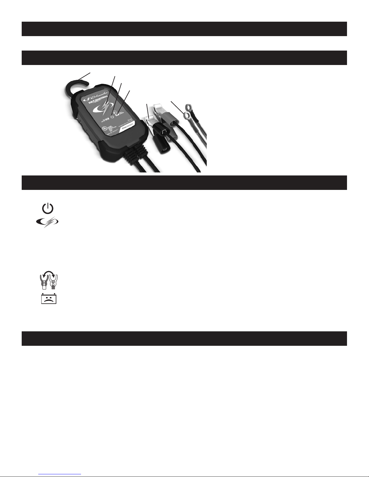
10. FEATURES
1
2
3
4
5 6
1. Hook attachment
2. Battery status LED
3. Power LED
4. Clamps Reversed LED
5. Battery clamps
(quick-connect)
6. Ring connectors
(quick-connect)
11. CONTROL PANEL
LED INDICATORS
POWER (green) LED lit: The charger is connected to AC power.
CHARGING INDICATOR:
Yellow/orange LED lit: The charger is charging the battery.
Yellow/orange LED ashing: The charger is in abort mode.
Green LED pulsing: The battery is fully charged and the charger is in
maintain mode.
CLAMPS REVERSED (red) LED ashing: The connections are reversed.
BAD BATTERY (red) LED lit: The charger has detected a problem
with the battery. See Troubleshooting for more information.
NOTE: See Operating Instructions for a complete description of the charger modes.
12. OPERATING INSTRUCTIONS
IMPORTANT: Do not start the vehicle with the charger connected to the AC outlet,
or it may damage the charger and your vehicle.
NOTE: This charger is equipped with an auto-start feature. Current is supplied
to the battery clamps before a battery is connected, and the clamps may spark if
touched together.
CHARGING A BATTERY IN THE VEHICLE
1. Turn off all the vehicle’s accessories.
2. Keep the hood open.
3. Clean the battery terminals.
• 7 •

4. Place the charger on a dry, non-ammable surface, or use the convenient hook
attachment to hang the unit safely outside the work area.
5. Lay the AC/DC cables away from any fan blades, belts, pulleys and other
moving parts.
6. Connect the battery, following the precautions listed in sections 6 and 7.
7. Connect the charger to a live grounded 120V AC outlet.
8. The green POWER LED will light.
9. When charging is complete, disconnect the charger from the AC power,
remove the clamps from the vehicle’s chassis, and then remove the clamp
from the battery terminal.
CHARGING A BATTERY OUTSIDE OF THE VEHICLE
1. Place battery in a well-ventilated area.
2. Clean the battery terminals.
3. Connect the battery, following the precautions listed in sections 6 and 7.
4. Connect the charger to a live grounded 120V AC outlet.
5. The green POWER LED will light.
6. When charging is complete, disconnect the charger from the AC power,
disconnect the negative clamp, and nally the positive clamp.
7. A marine (boat) battery must be removed and charged on shore.
USING THE QUICK-CONNECT CABLE CONNECTORS
Connect either of the two (2) output cable leads to the charger. Make sure to place
the charger on a dry, non-ammable surface.
WARNING: Never connect the clamp and ring terminal connectors together for
use in other applications, such as external battery or other power source charging,
or to extend the output cable length, as reverse polarity and/or overcharge
conditions will occur.
USING THE 50 AMP BATTERY CLAMPS
1. Connect the end of the charger output cable to the end of the battery cable,
quick-connect and clamps.
2. Follow the steps in sections 6 and 7, to connect the output clamps to the battery.
3. Connect the charger to a live 120V AC outlet.
USING THE RING CONNECTORS
1. To permanently attach to a battery, loosen and remove each nut from the bolt
at the battery terminal.
2. Connect the red POSITIVE connector ring to the POSITIVE battery terminal.
3. Connect the black NEGATIVE connector ring to the NEGATIVE battery terminal.
4. Replace and tighten the nuts to secure.
• 8 •
5. Connect the cable to the end of the charger output cord.
Take care to keep the wires and plug away from metal and moving parts.
6. Connect the charger to a live grounded 120V AC outlet.
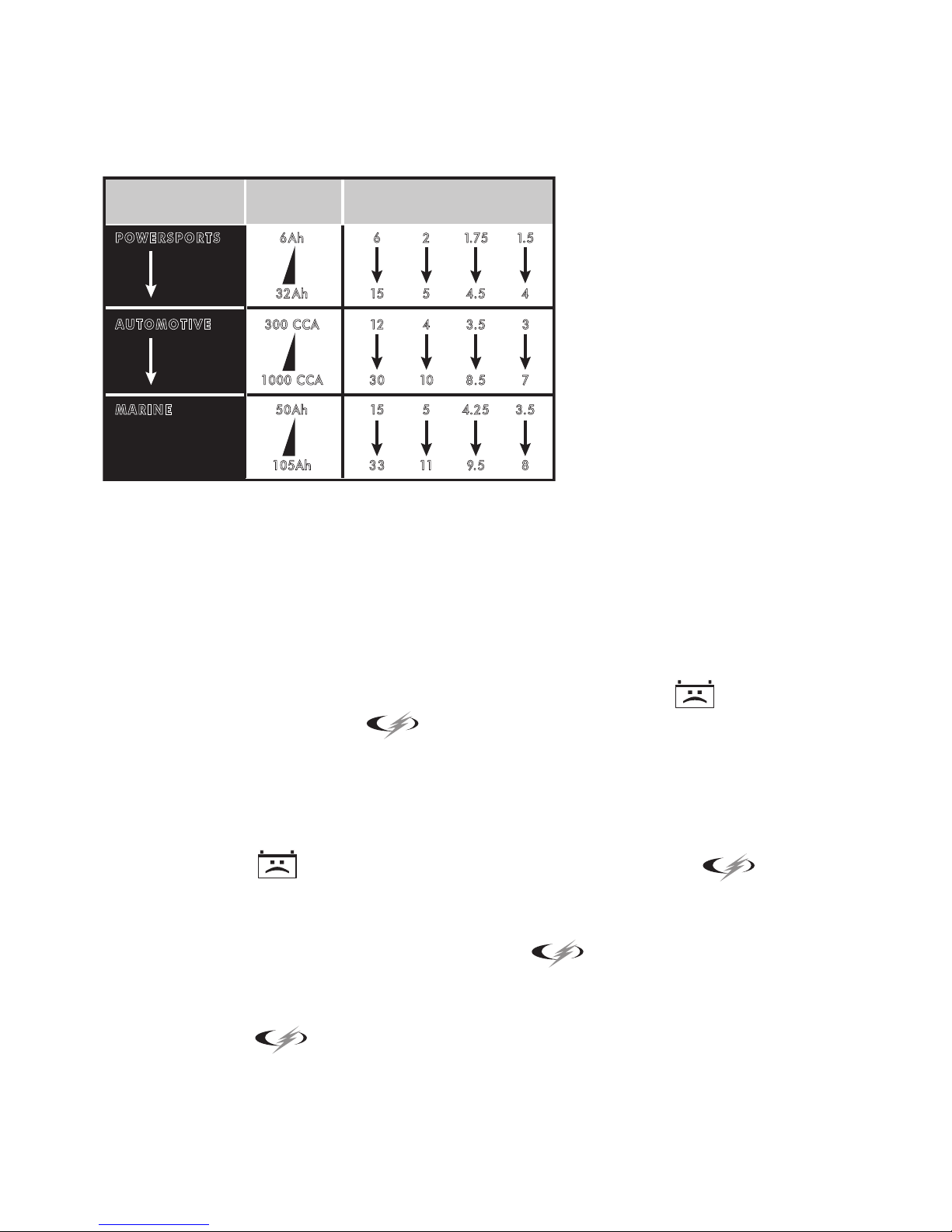
BATTERY CHARGING TIMES
APPLICATION
POWERSPORTS
AUTOMOTIVE
MARINE
BATTERY
SIZE
6Ah 6
32 Ah 15
300 CCA 12
1000 CCA 30
50 Ah 15
105Ah 33
CHARGING TIME (Hours)
2A 6A 8A 10A
2
10
11
1.7 5
5
4.5
4
3.5
8. 5
5
4.2 5
9.5
1. 5
4
3
7
3.5
8
Times are based on a 50% discharged battery and may change, depending on age
and condition of battery.
AUTOMATIC CHARGING MODE
When an Automatic Charge is performed, the charger switches to the maintain
mode automatically after the battery is charged.
ABORTED CHARGE
If charging cannot be completed normally, charging will abort. When charging
aborts, the charger’s output is shut off. The BAD BATTERY (red) LED will
light and the yellow/orange
(CHARGING) LED will ash. Do not continue
attempting to charge this battery. Do not continue attempting to charge this battery.
Check the battery and replace, if necessary.
DESULFATION MODE
Desulfation could take 8 to 10 hours. If desulfation fails, charging will abort. The
BAD BATTERY (red) LED will light and the yellow/orange
(CHARGING)
LED will ash.
COMPLETION OF CHARGE
Charge completion is indicated by the green
(CHARGED) LED. When
pulsing, the charger has switched to the maintain mode of operation.
MAINTAIN MODE (FLOAT-MODE MONITORING)
When the green
(CHARGED) LED is pulsing, the charger has started maintain
mode. In this mode, the charger keeps the battery fully charged by delivering a small
current when necessary. If the charger has to provide its maximum maintain current for
a continuous 12 hour period, it will go into abort mode (see Aborted Charge section).
This is usually caused by a drain on the battery or the battery could be bad. Make sure
• 9 •
 Loading...