

SCHOLTES TGL 641,TGL 751,TGL 641 Operating Instructions Manual

Gas Hob Operating Instructions
Page 1 of 11
English
Contents
AU
Installation, 2-5
!
Positioning
!
Electrical Connection
!
Gas Connection
!
Data Plate
!
Burner & Injector Specification
!
!
Description of the Appliance, 6
!
Overall View
!
!
Start-up and Use, 7-8
!
Practical advise on using the burners
!
TGL 641
Precautions and Tips, 9
TGL 751
General Safety
!
Disposal
!
!
Maintenance and Care, 10
!
Switching the appliance off
!
Cleaning the appliance
!
Gas tap maintenance
!
!
Troubleshooting, 11
!
!
!
!
!
!
!
!
!

Gas Hob Operating Instructions
Page 2 of 11
Installation
! Before operating your new appliance please read
this instruction booklet carefully. It contains
important information for safe use, installation and
care of the appliance.
! Please keep these operating instructions for
future reference. Pass them on to possible new
owners of the appliance.
! Keep packaging material out of the reach of
children. It can become a choking or suffocation
hazard (see Precautions and tips)
! This appliance shall be installed only by
authorised personnel and in accordance with the
manufacturer’s installation instructions, local gas
fitting regulations, municipal building codes, water
supply regulations, electrical wiring regulations,
AS 5601/AG 601 - Gas Installations and any other
statutory regulations.
! Ventilation - Ventilation must be in accordance
with AS5601/AG 601 - Gas Installations. In
general, the appliance should have adequate
ventilation for complete combustion of gas, proper
flueing and to maintain temperature of immediate
surrounding within safe limits.
Positioning - The appliance can be fitted into a
working area as illustrated on the corresponding
figure. Apply the seal provided over the whole of
the area perimeter.
Combustible Surfaces - Any adjoining surface
situated within 200mm from the edge of any hob
burner must be a suitable non-combustable
material for a height of 150mm for the entire
length of the hob. Any combustible construction
above the hotplate must be at least 600mm above
the top of the burner and no construction shall be
within 450mm above the top of the burner. A
minimum depth of 60mm from the top of the
worktop surface must be provided for the
appliance.
Access to base - Where the base of the hotplate
can be accidentally touched, such as through a
cupboard or a pot drawer, a panel should be fixed
15mm below the base of the hotplate to prevent
accidental contact. The base of the hotplate is
very hot during operation.
Data Label - The Data Label is located on the
underside of the appliance. A duplicate label is
supplied to adhere in an accessible area adjacent
to the appliance. This appliance is suitable for
Natural and Propane Gas; ensure the available
gas supply matches the data label.
Gas connection - The Gas Connection is male
1/2” BSP and is situated 50mm from the right,
50mm from the rear of the hotplate and 25mm
below the top surface of the bench top.
There are two ways to carry out the connection to
the main gas line:
A. The hotplate can be connected with rigid
pipe as specified in AS5601 table 3.1.
B. The hotplate can be connected with a
Flexible Hose, which complies with
AS/NZS 1869 (AGA Approved), 10mm
ID, class B or D, no more than 1.2m long
and in accordance with AS5601
Ensure that the Hose does not contact the hot
surfaces of the hotplate, oven, dishwasher or
other appliance that may be installed underneath
or next to the hotplate.
The hose should not be subjected to abrasion,
kinking or permanent deformation and should be
able to be inspected along its entire length. Unions
compatible with the hose fittings must be used and
connections tested for gas leaks. The supply
connection point shall be accessible with the
appliance installed.
When the installation has been carried out, check
the perfect sealing of the entire connection
system, by using soapy solution.
Power Connection - Simply plug into a 3 pin
household socket outlet which is properly earthed.
Warning: In order to avoid hazard, any electrical
work performed on this equipment or its
associated wiring, should only be done by persons
authorised by the supplier or similarly qualified
persons.
The socket outlet for this hotplate shall be installed
near the hotplate and shall be easily accessible.
Gas Hob Operating Instructions
Page 3 of 11
MODEL
L (mm)
W (mm)
Electrical Connection
The hobs come equipped with a 3 pin plug and
power cable. The plug and power cable comply
with Australian requirements. Please check the
power rating, voltage and frequency indicated on
the data plate (located on the bottom of the hob as
well as on the front cover of this manual).
If the appliance is to be installed above an electric
built-in electric oven, the electrical connection to
the hob and oven must be carries out separately,
both for electrical safety purposes and to make it
easier to remove the oven.
The supply cable must not come into contact with
surfaces higher than 50°C.
! The installer must ensure the electrical
connection has been made and is compliant with
AS/NZS 3000 wiring rules.
Before connecting to the power supply, make sure
that:
• The appliance is earthed and the plug is
compliant with the law.
• The socket can withstand the maximum
power of the appliance, which is indicated
on the data plate.
• The voltage is in the range between the
values indicated on the data plate.
• The socket is compatible with the plug of
the appliance. If the socket is
incompatible with the plug, ask an
authorised technician to replace it. Do not
use extension cords or multiple sockets.
! Once the appliance has been installed, the power
supply cable and the electrical socket must be
easily accessible.
! The cable must not be bent or compressed.
! The cable must be checked regularly and
replaced by authorised technicians only (see
Assistance).
! The manufacturer declines any liability should
these safety measures not be observed.
Adapting to various types of gas
Warning: Servicing should be carried out only by
authorised personnel. Should the appliance be
pre-set for a different type of gas than that
TGL 641
640
520
TGL 751
680
520
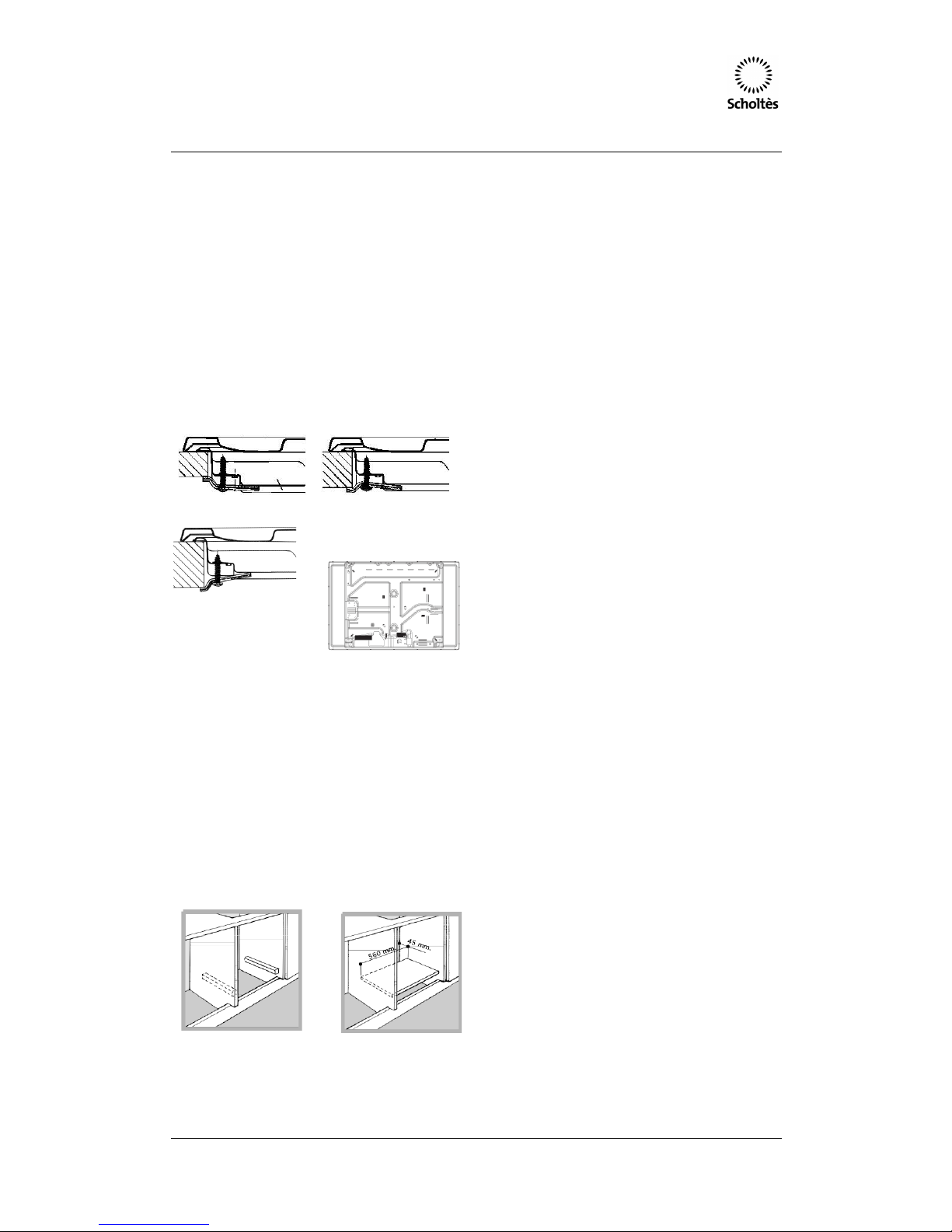
Bench cutout for both models is 555mm x 475mm
The installation cavity should have the dimensions
indicated in the figure.
Fastening hooks are provided, allowing you to
fasten the hob to tops that are between 20 and 40
mm thick. To ensure the hob is securely fastened
to the top, we recommend you use all the hooks
provided.
Hook fastening diagram
Hooking position Hooking position
For top H=20 mm for top H=30 mm
Hooking position
For top H=40 mm
Front
Back
! Use the hooks contained in the “accessory pack”
Where the hob is not installed over a built-in oven,
a wooden panel must be installed as insulation.
This must be placed at a minimum distance of 20
mm from the lower part of the hob.
Ventilation
To ensure adequate ventilation, the back panel of
the cabinet must be removed. It is advisable to
install the oven so that it rests on two strips of
wood, or on a completely flat surface with an
opening of at least 45 x 560 mm (see diagrams).
! The Hob can only be installed above built-in
ovens with a cooling ventilation system.
Gas Hob Operating Instructions
Page 4 of 11
available, proceed as follows:
− replace the injectors with the
corresponding type of gas to be used (see
table “Uses characteristics”).
− to adjust to the minimum, use a
screwdriver on the screw placed on the tap
after turning the tap to its minimum
position.
To adapt the hob to a different type of gas other
than default type (indicated on the rating plate at
the base of the hob or on the packaging), the
burner nozzles should be replaced as follows:
1. Remove the hob grids and slide the
burners off their seats.
2. Unscrew the nozzles using a 7 mm
socket spanner, and replace them with
nozzles for the new type of gas (see
table 1 “Burner and nozzle
characteristics”).
3. Reassemble the parts following the
above procedure in the reverse order.
4. Once this procedure is finished, replace
the old rating sticker with one indicating
the new type of gas used. Sticker are
available from any of our Service
Centres.
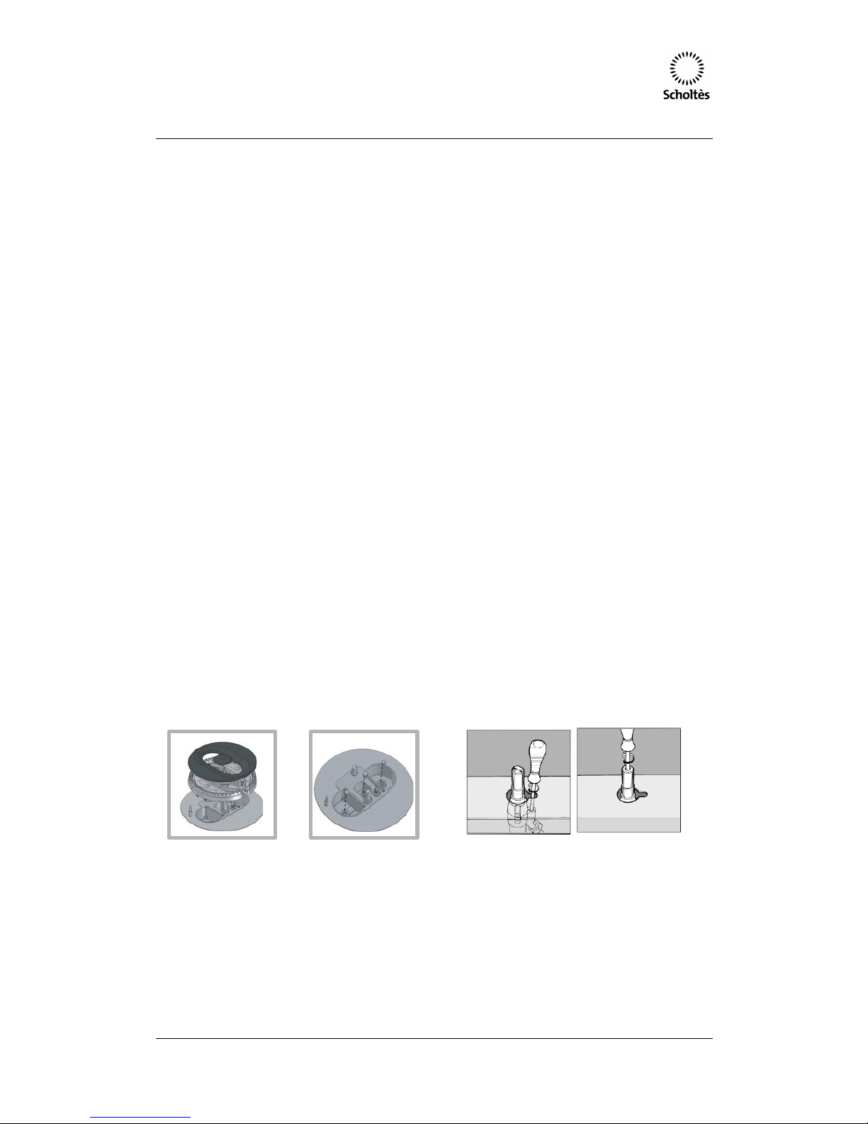
Replacing the nozzles on separate “double flame”
burners:
1. remove the grids and slide the burners
from their housings. The burner consists
of 2 separate parts (see figure);
• Setting the burners to minimum:
1. Turn the tap to the low flame position.
2. Remove the knob and adjust the
adjustment screw, which is positioned in
or next to the tap pin, until the flame is
small but steady.
3. Having adjusted the flame to the required
low setting, while the burner is alight,
quickly change the position of the knob
from minimum to maximum and vice
versa several times, checking that the
flame does not go out.
4. Some appliances have a safety device
(thermocouple) fitted. If the device fails to
work when the burners are set to the low
flame setting, increase this low flame
setting using the adjusting screw.
5. Once the adjustment has been made,
replace the seals on the by-passes using
sealing wax or a similar substance.
When converting from Natural Gas to Propane
ensure that the NG regulator is removed and
replaced with the test point assembly. A gas
regulator suitable for a supply pressure of
2.75kPa should be part of the gas tank supply and
should be adjusted with the wok burner operating
at maximum.
The appliance is factory set for Natural Gas. The
test point pressure should be adjusted to 1.00kPa
with the wok burner (or rapid burner if there is no
wok burner) operating at maximum.
6. Unscrew the burners with a 7 mm
wrench spanner. The internal burner has
a nozzle, the external burner has two (of
the same size). Replace the nozzle with
models suited to the new type of gas
(see table page 5).
7. Replace all the components by repeating
the steps in reverse order.
• Adjusting the burners primary air:
Does not require adjusting.
Replace the old data plate with one which is
suitable for the type of gas for which the appliance
has been regulated.
Before Leaving - Check all connections for gas
leaks with soap and water. DO NOT use a naked
flame for detecting leaks. Ignite all burners to
ensure correct operation of gas valves, burners
and ignition.
 Loading...