

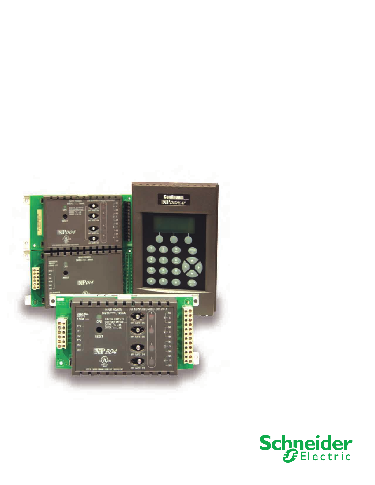
Andover ContinuumTM
xP Expansion I/O Family
The Andover Continuum xP Expansion I/O Family provides a
convenient and cost-effective means to add additional inputs,
TM
outputs, or a local display to the Andover Continuum Infinet
TM
and BACnet
family of distributed controllers.
II
Andover Continuum xP Expansion I/O Family
Features
Up to two modules plus a local display
can be powered directly from any of
the following controllers in the Andover
Continuum Infinet II (i2) or BACnet (b3)
families: i2/b3 920, i2/b3 810, i2/b3 814, i2/
b3 850, i2/b3 851, or i2/b3 853.
The bCX1 Controller/Router models can also
be used to connect xP Expansion Modules (and
Display) and are the only controllers that support the
xPBA4 and xPBD4 module types. No external power
supply is required to power the Module(s). Consult
the xP Modules and Local Display Modules User
Guide for valid configurations.
02
PRODUCT AT A GLANCE
• Powerfu l, Flexi ble Sy stem Allows f or Simp le
Addi tion of a Few I/ O Points
• Individual Overrides of All Digital Outputs
• U niversa l Input s Provide the Most Flexi bility,
Including a Single High Speed Counter Input
• Indi vidual Overrid es and Potentio meters for
All Analog Outputs
• Full Functio n Manua l Overr ides Pr ovide
Status Feedback
• 4-Li ne, 16- charact er Disp lay wit h Keypad
Provi des Simple and C onvenien t Operat or
Interface
• Local ly Mou nted or Remote Mount o f
Modules and Display
• Modu le Powe r Suppl ied by the Controlle r,
Reducing Installation Time and Cost
• xPDI8 – The xPDI8 module allows the addition
of 8 Digital Inputs in a small enclosure.
• xPUI4 – The xPUI4 module allows the addition
of 4 Universal Inputs. Each can be configured
independently based on your needs for Digital,
Temperature, Motion Sensor, or Pulse Counter
Inputs, etc., providing built-in flexibility for your
different application requirements.
• xPAO2/xPAO4 – Both the xPAO2 (2 Analog
Outputs) and the xPAO4 (4 Analog Outputs)
allow the addition of Analog Outputs. Each
output has individual manual override switches to
select Manual, Off, or Auto for program control.
When in Manual mode, each output also has a
potentiometer to allow control of the override point.
• xPDO2/xPDO4 – Both the xPDO2 (2 Digital
Outputs) and the xPDO4 (4 Digital Outputs) allow
the addition of Digital Outputs. Each output has
individual manual override switches to select On,
Off, or Auto for program control.
• xPBA4/xPBD4 – Both the xPBA4 and the xPBD4
combine the functions of two xP Expansion
modules. Similar to the xPUI4, both allow the
addition of 4 Universal Inputs. The xPBA4 allows
the addition of 4 Analog Outputs (like the xPAO4),
and the xPBD4 allows for the addition of 4 Digital
Outputs (like the xPDO4). (Note: The xPBA4 and
xPBD4 Expansion Modules can only be connected
to the bCX1 Controller/Routers and ACX Series
Access Controllers.)
Schneider Electric
SDS-XPEXPANSION-I/O-US.BU.N.EN.8.2007.0.00.CC

Andover Continuum xP Expansion I/O Family
03
Features
(continued)
Expansion I/O Family
xPDI8
INPUTS
xPUI4
INPUTS
xPAO 4 xPDO4
OUTPUTS
xPAO 2
OUTPUTS
Similar to xPAO4;
however only the first
2 outputs are populated.
Local Display
The local display with keypad (xP Display) allows for
the addition of a fully programmable local display
module that can be mounted within 10 feet (3
meters) of the controller. Connected via a ribbon
cable, the xP Display easily allows the Operator
Interface to be mounted on the door of an enclosure
or on a wall below or next to the controller.
OUTPUTS
xPDO2
OUTPUTS
Similar to xPDO4;
however only the first
2 outputs are populated.
Programming
Programming with the Expansion Modules points
are treated in the same manner as the built-in I/O
points on the controller. Once the points have been
configured, they are available for graphics, Plain
EnglishTM programming, or for displaying data on
the display.
Schneider Electric
SDS-XPEXPANSION-I/O-US.BU.N.EN.8.2007.0.00.CC

Andover Continuum xP Expansion I/O Family
04
Features
(continued)
Expansion I/O Family
INPUTS OUTPUTS
xPBA4
xPBD4
INPUTS OUTPUTS
Dimensional Drawings
xP Module
I
nstallation
Modules can be connected to the bottom of the
controller with the built-in expansion port connector
or they may be connected remotely via a 3-foot (~1
m) or 10-foot (~3m) ribbon cable. A total of 10 feet
of cable may be used for all Expansion Modules.
Mounting and securing of the xP modules is provided
through four mounting holes in the base plate.
xP Display
Models
xP-Disp lay
(includ es 3 foot cable)
xP-Disp lay-10
(includ es 10 foot cable)
Power Consumption
70 mA
Display Prop erties
4 lines x 16 characters,
backlit
Enclosure Type
IP54 Rati ng
Schneider Electric
SDS-XPEXPANSION-I/O-US.BU.N.EN.8.2007.0.00.CC

Andover Continuum xP Expansion I/O Family
Specifications
xP Expansion I/O
05
Electrical
Power
Up to two I/O module and an xP-Display may
be connected to a controller. All controllers
provide a total of 180 mA of power, the bCX1
controller/router has 400 mA of power, for the
modules. Each module’s power consumption
is listed below. Reference installation sheet for
valid combinations.
Mechanical
Operating Environment
32°–120°F (0–49°C),
10–95% RH (non-condensing)
Size
Module: 3.21˝ H x 7.10˝ W x 1.60˝ D
(82H x 180 W x 41 D) mm
Display: 7.25˝ H x 5.00˝ W x 1.65˝ D
(184H x 127 W x 42 D) mm
Weight
Module: 0.48 lb (0.22 kg)
Display: 1lb (0.45 kg)
Enclosure Type
Modules: UL Open class, IP 10.
Flammability rating of UL94-5V
Display: IP54
Communications
Communications Interface
Through built-in Expansion Port
on controller
Connections
Fixed Terminal Connectors
Reference specific module on previous
page for terminal point assignments
Input (top)
6-pin shrouded connector
Output (bottom)
6-pin shrouded connector
User LEDs/Switches
Status Indicator LEDs
CPU Module is Active
Switches
RESET
General
xP Modules
Consult the xP Module Installation
Guide for the maximum number
of inputs/outputs allowed on
each controller.
Cable Options
xP-Mod-Cable-3
3-foot (~1m) ribbon cable terminated
xP-Mod-Cable-10
10-foot (~3m) ribbon cable terminated
Agency Listings
UL/CUL 916, FCC CFR 47 Part 15,
ICES-003, EN55022, AS/NZS 3548,
Class A, CE
xPDI8 (Digital Inputs)
Points
8 Digital Inputs
Power Consumption
25 mA
Voltage
0-5 VDC, or contact closure
Input Impedance
10K ohm ref to +5VDC
Frequency
140Hz, 50% duty cycling, 3.57 ms
pulse width min.
Overvoltage Protection
24 VAC/DC +/- 1500 V transients
Schneider Electric
SDS-XPEXPANSION-I/O-US.BU.N.EN.8.2007.0.00.CC

Andover Continuum xP Expansion I/O Family
06
Specifications
xP Expansion I/O
xPUI4/xPBA4/xPBD4
(Universal Inputs)
Points
4 Universal Inputs
Power Consumption
50 mA (xPUI4)
60 mA (xPBA4)
125 mA (xPBD4)
Voltage
0-5.115 VDC
Input Impedance
10K ohm ref to +5VDC
Frequency
4Hz, 50% duty cycling,
125 ms pulse width min. (Inputs 1-3)
140Hz, 50% duty cycling, 3.57 ms
pulse width min. (Input 4)
Overvoltage Protection
24 VAC/DC +/- 1500 V transients
(continued)
xPAO2/xPAO4/xPBA4
(Analog Outputs)
Points
2 Analog Outputs (xPAO2)
4 Analog Outputs (xPAO4, xPBA4)
Power Consumption
80 mA (xPAO2)
120 mA (xPAO4)
60 mA (xPBA4)
Output Rating
0-10 VDC
4-20mA per channel (xPAO2, xPAO4)
Output Resolution
0.1V for 0-10V
0.1mA for 4-20mA (xPAO2, xPAO4)
Overrides
yes – per output point. Software
feedback of the switch position is
provided, for display and alarming
Potentiometer
yes – per output point
N1831
xPDO2/xPDO4/xPBD4
(Digital Outputs)
Points
2 Digital Outputs (xPDO2)
4 Digital Outputs (xPDO4, xPBD4)
Type
2 or 4 single pole single throw (SPST)
Form C relays
Power Consumption
60 mA (xPDO2)
100 mA (xPDO4)
125 mA (xPBD4)
Output Rating
Maximum 3A, 24 VAC/VDC,
+/- 1500 V transients (tested
according to EN61000-4-4)
Output Accuracy
0.1 sec for pulse width modulation
Output Overrides
Each Output is equipped with a
manual override switch. Software
feedback of the switch position is
provided, for display and alarming
All brand names, trademarks and registere d trademarks are the property of their respective owners. Information contained within this document is subject to change
without notice.
On October 1st, 2009, TAC became the Buildings Business of its parent company Schneider Electric. This document reflects the visual identity of Schneider Electric, however there remains references to TAC as a corporate brand in the body copy. As each document is updated, the body copy will be change d to reflect appropriate corporate
brand changes.
Schneider Electric
SDS-XPEXPANSION-I/O-US.BU.N.EN.8.2007.0.00.CC
August 20 07 pdw
© 2007-20 09 Schneider Electric. All rights reser ved.
 Loading...