

Page 1
Installation Instructions
VBB/VBS Series Ball Valves
with Proportional Actuators
Vertical Pipe
A AB
SHEET 12
SHEET 12
Inspection
Inspect the package for damage. If package is damaged,
notify the appropriate carrier immediately. If undamaged, open
the package and inspect the device for obvious damage.
Return damaged products.
Two-Way Valve: Flow A to AB Three-Way Valve: Mixing Only A
Requirements
NOTICE
RISK OF EQUIPMENT DAMAGE
•
Read and understand these instru
servicing this product.
Do not install this product in haz
•
locations unless expressly permi
•
Turn off all power supplying equ
the product.
•
Make all connections in accorda
diagram.
• Do not exceed the product’s technical ratings.
Use copper conductors only
•
accordance with the appropriate
Avoid installation locations expo
•
moisture, and/or corrosive or ex
•
Avoid electrical noise interferenc
conductors, electrical machinery
•
When making wiring connections within the actuator
put leads or connectors below the
•
This product is a class 2 (Limited V
device.
The installer is responsible for co
•
codes.
Check the Electrical terminals a
•
settings before powering up the
Failure to follow these instructions may cause equipment
damage.
ctions before installing or
ardous or classified
tted.
ipment before working on
nce with the electrical wiring
. Make all connections in
electrical wiring diagram.
sed to vibration, excessive
plosive vapours.
e. Do not install near large
, or welding equipment.
motor.
oltage Limited Energy)
nformance to all applicable
nd any configuration switch
actuator.
M113A0x or M123A0x
, do not
A
and/or B to AB.
B
M133A0x
AB
If this product is used in a manner not specified by the manufacturer,
the protection provided by the product may be impaired.
No responsibility is assumed by Schneider Electric for any
consequences arising out of the use of this product.
Tools (not provided)
• Wrench/adjustable spanners: 24…42mm (1”…1-5/8”)
• Pipe wrench according to pipe size
• Volt-ohm multimeter
• Phillips Head screwdriver
© 2016 Schne ider Ele ctric. All rights rese rved. All trademar ks are ow ned by Sch neider Electr ic Indust ries S AS or its affi liated co mpanie s. November, 2017 tc
Docume nt Numbe r: F-27394-10
Horizontal Pipe
Horizontal Plane
Training
• Installer must be a qualified, experienced technician
Other accessories
• As appropriate.
90
Vertical Pipe
Page 2
Installation Instructions
Piping
NOTICE
RISK OF EQUIPMENT DAMAGE
•
Do not install in open systems using substantial make-up water.
• Follow proper water treatment practices and system
procedures.
Failure to follow these instructio
damage.
These valves must be piped according to the water flow
diagram. Two-Way valve flow should go A to AB. Three-way
valves should be applied only as mixing valves (see diagram).
Best Practice Guidelines
It is recommended to fit a strainer upstream of the valve to
increase reliability and to follow water treatment guidelines as
detailed in VDI 2035.
Recommendations
The pipework system should be flushed prior to the operation.
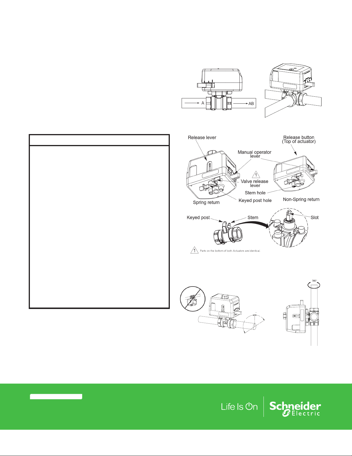
Mounting
The valves can be mounted in horizontal or vertical piping.
When installed in horizontal piping, the actuator must be above
the valve body. It can be tilted left or right but it must not be
tilted below 90° from vertical.
Installation Notes
• Confirm there is no overhead water source that may drip
onto valve actuator.
• In normal service, some condensation may occur on or
around the valve. A drip pan may be necessary or the valve
body may be insulated.
• Do not cover the actuator or obstruct the manual operator
lever.
• Reference product label and Product Datasheet F-27895 for
additional product specifications.
It is the responsibility of the installer or product specifier to
verify media compatibility of the valves construction materials
with the supplier of water treatment/heat transfer solution.
Installing the Valve Body
Apply PTFE tape to the male pipe thread. Hand screw the pipe
into the valve, turning it as far as it will go. Use a wrench to fully
tighten the valve to the pipe. Do not over tighten or strip the
threads.
Installing the Actuator on the Valve Body
1. Turn the valve stem so the slot on top of the stem is
pointing towards the large keyed post.
2. Do one of the following:
• For a spring return actuator, press the red lever down
and rotate the manual operating lever to align the stem
hole with the valve stem. Then slide the red lever up to
lock the manual lever in place.
• For a non-spring actuator, press and hold the red
release button on the top of the actuator and rotate the
ns may cause equipment
manual operating lever to align the stem hole with the
valve stem, then release the red button.
3. Align the valve body with the actuator so the stem lines up
with the large stem hole and the large keyed post lines up
with the post hole on the bottom of the actuator.
4. Firmly press the valve and actuator together to lock into
place.
The first time the valve is operated electrically, the manual
operating lever of the actuator will move to the automatic
position. The manual operating lever can be used to allow
flushing of the system after installation.
Removing the Actuator
NOTICE
RISK OF EQUIPMENT DAMAGE
•
Do not use the valve body to manually open the actuator.
Failure to follow this instruction will result in damage to
the actuator
NOTE: Make sure the valve stem rotates freely before and
after installing the actuator. If the stem does not operate freely
it may indicate that the stem was damaged and may require
that the valve be replaced.
1. Press and hold the valve release lever inward, towards the
valve.
2. Lift the actuator from the valve.
3. After the piping is under pressure, check the valve body
and the connections for leaks.
4. After the valve and actuator are installed, power the
actuator and check the operation by varying the control
signal. On spring return models, the valve should return to
its normal position when power is removed.
Theory of Operation
This series of proportional valve actuator assemblies is
designed to make incremental adjustments to flow based
on the control signal input. This actuator is not intended for
continuous use in zero dead band control systems.
When power is removed for more than two seconds, spring
return valve assemblies return to their normal position. Nonspring return valve assemblies remain at their last position
when power is removed. The spring return feature should not
be used for routine, normal operation.
Proportional Actuators perform a self-calibration cycle on
power-up. The actuator will run to the open direction for
approximately 20 seconds and then closed direction for
145 seconds (approximately 2 ½ min.). Once this cycle is
complete, the actuator will then accept and respond to the
control signal.
NOTE: Do not use the manual operator while power is applied
to the actuator. If the actuator is manually positioned while
power is applied, the calibration cycle must be completed
again for the actuator to function properly. To recalibrate the
actuator, cycle power off for more than 6 seconds.
.
November, 2017 tc © 2016 Schne ider Ele ctric. All rig hts rese rved. All trademar ks are ow ned by Sch neider Electr ic Indust ries S AS or its affi liated co mpanie s.
Document Number: F-27394-10
Page 3

Installation Instructions
AB
A
0-10V Direct Acting
1 2 3 4 5 6
1 2 3 4 5 6
1 2 3 4 5 6
1 2 3 4 5 6
0-10V Direct Acting
0-5V Direct Acting
5-10V Direct Acting
2-10V Direct Acting
g
0
g
Maintenance
The ball valve assembly itself requires no maintenance. The stem and
packing design eliminates the need for packing adjustment for the
life of the valve. However, regular maintenance of the total heating
and cooling system is recommended to establish sustained optimum
performance.
Field Repair
Neither valve nor actuator are field repairable.
Application Schematics
Typical applications
For simplicity, balancing valves and control devices not shown.
Return
Supply
Supply
AAB
Typical Two-Way
Fan Coil Application
Wiring and Wiring Diagrams
Make all connections according to job wiring diagrams and in
compliance with local and national electrical codes. See the diagrams
for typical wiring.
• Multiple actuators may be connected to a single controller.
• Do not exceed the maximum current draw of the controller.
• Use only one spring return actuator per 10 VA transformer.
• Use properly sized, inherently limited, Class 2 transformer(s).
• Use only 18…24 AWG (0.75…0.22 mm2) copper wire for all
connectors.
• For 4…20 mAdc control, a separate isolation transformer must be
used with each valve.
Control Signal and Action Selection
M1 Proportional models have a DIP switch module for mode selection
located behind a door/flap on the side of the actuator. The drawings
show the module sideways.
• Actuators are shipped from factor y with SW1 ON and SW2-6 OFF
for 0…10 Vdc control signal and for direct action (DA; valve opens
with increasing control signal).
• When using SW1 through 4, the lowest numbered dip switch set
to ON takes priority, e.g. if both SW2 and SW4 are ON, SW2 takes
precedent.
• SW5 must be ON (SW1 through SW4 must be OFF) for 4-20 mA
mode.
• For more information see Guidelines for Powering Multiple
Actuators EN-206 (F-26363).
Typical wiring with a Non-Spring Return Actuator
Three-Way
Constant Flow
Variable Temperature
Power/Failure Action (Proportional)
Control Signal
DA Dip Switch selected
(SW6 OFF)- Increase in
control signal will open A
to AB
RA Dip Switch selected
(SW6 ON)- increase in
control signal will close A
to AB
NOTE: Two- Way valve op erati on described. For a thre e-way v alve, A to AB operat ion is th e
same. B to A B opera tion is op posite t hat of A to AB operat ion.
Typical Three-Way
Fan Coil Application
Return
Supply
Return
Bypass
B
AB A
Mixing applications
B
Bypass
Position upon power loss
Non-Spring
Return Actuator
Maintain last
position
Spring Return
Open Actuator
- Fail Open
Will spring A
to AB open
Spring Return
Closed
Actuator - Fail
Closed
Will spring A to
AB closed
Typical wiring with a Spring Return Actuator
1 2 3 4 5 6
0-5V Direct Acting
1 2 3 4 5 6
5-10V Direct Acting
1 2 3 4 5 6
OFF
ON
OFF
ON
OFF
ON
OFF
ON
1 2 3 4 5 6
4-20mA Direct Actin
OFF
ON
1 2 3 4 5 6
-10V Reverse Actin
OFF
ON
© 2016 Schne ider Ele ctric. All rights rese rved. All trademar ks are ow ned by Sch neider Electr ic Indust ries S AS or its affi liated co mpanie s. November, 2017 tc
Docume nt Numbe r: F-27394-10
Page 4

Dimensions (mm)
Notched Stem
Notched Stem
5-1/8
(130)
4-3/8
(111)
1/16 (2)
3/8 (10)
1/16 (2)
4-3/8
(111)
5-1/8
(130)
Installation Instructions
2-3/8
(60)
3-3/4
1-3/8
(35)
1-3/8
(95)
3/4 (19)
1-3/8
(35)
2-9/16
(65)
5-1/8
(130)
4-3/8
(111)
1/2 (12)
3-9/16
(90)
4-7/8
(124)
3/4 (19)
1-3/8
(35)
(35)
2-9/16
(65)
2-1/2
2-1/2
1-11/16
(64)
(64)
(43)
1-11/16
(43)
3/8 (10)
2
(50)
2
(50)
An additional 1 inch is required to remove the actuator from the valve.
3-3/4
(95)
4-7/8
(124)
2-3/8
(60)
3/4 (19)
1/2 (12)
3-1/16
(78)
2-9/16
(65)
1-3/8
(35)
2-9/16
(65)
1-3/8
(35)
4-3/8
(111)
1-3/8
(35)
5-1/8
(130)
1-3/8
(35)
1-11/16
(43)
1-11/16
(43)
2-1/2
(64)
2-1/2
(64)
2-3/16
(56)
2-3/16
(56)
Flow Direction
A notch is cut into the tip of the valve stem. This notch is an external indicator of the closed portion of the ball within the valve.
Check the notch position prior to assembling the actuator to verify the ball is orientated in the correct plane.
The drawings below indicate the stem notch position and the corresponding ball valve flow path.
Notched Stem
Ball Position
or
A
Two-Way Open
Ball Position
A
B
Three-Way, A-Port Open, B-Port Closed
AB
AB
Notched Stem
Ball Position
or
A
Two-Way Closed
Ball Position
A
Three-Way, A-Port Closed, B-Port Open
Stem Indicator
ABA
AB
ClosedOpen
B
Agency Listings
European Community: EMC Directive 2014/30/EU. Low Voltage Directive 2014/35/EU. UL873 Listed: Underwriters laboratories
(File #E9429 Category Temperature Indicating and Regulating Equipment) CUL: Listed for use in Canada by Underwriters
Laboratory. Canadian Standards C22.2 No. 24. Australia: This product meets requirements to bear the RSM mark according to the
terms specified by the Communications Authority under the Radio Communications Act of 1992.
November, 2017 tc © 2016 Schne ider Ele ctric. All rig hts rese rved. All trademar ks are ow ned by Sch neider Electr ic Indust ries S AS or its affi liated co mpanie s.
Document Number: F-27394-10
 Loading...