

Page 1

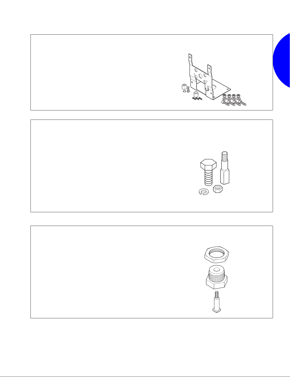
Valve Linkages
Val
Application
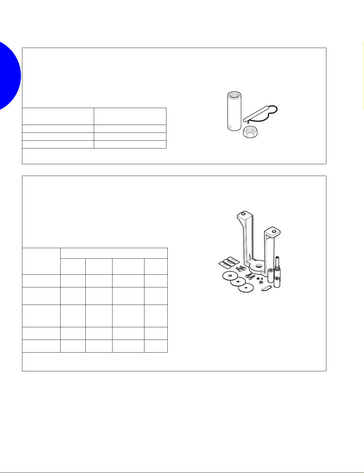
For assembling electric gear train actuators to valve bodies.
The AV-390 through A V -396 linkages are used to field assemble
Invensys gear train actuators and VB-9XXX and VB-7XXX
series of valve bodies.
Features:
• Die case aluminum mounting bracket.
• Valve position indication provided as standard.
Specifications
• Actuator mounting: In any upright position with actuator above
the center line of the valve body.
AV-29, AV-30, AV-9X Series ,
AV-300, AV-347, AV-39X Series
Electric/Electronic Valve Linkage Kits
ve
Linkages
Minimum Actuator
Model No. Description
AV-29
AV-30
AV-91
AV-92
AV-93
AV-94
AV-300
AV-347
AV-347-10
AV-347-20
AV-347-30
AV-390
AV-391
AV-392
AV-393
AV-394
AV-395
AV-396
a
Used on obsolete 1-1/2 & 2” VB-9XXX valves with spring return actuators only.
b
Used on obsolete 1-1/2 & 2” VB-9XXX valves with non-spring return actuators only.
Cam, Plunger and
Connection Pin Kit
a
Cam, Plunger and
Stem Extension Kit
b
Common Parts Kits
Req. AV-29, 30
Complete Linkage
Common Parts Kits
Req. AV-91, 92, 93, 94
a
Complete Linkages
b
Tor que Required
(Actuator must be
°
Stroke) (lb-in.)
180
50 150
100 300
40 150
50 150
70 300
100 300
50 150
100 300
50 150
100 300
40 150
50 150
70 300
100 300
50 150
100 300
Stem
Force
(lb)
857
Page 2

Valve Linkages
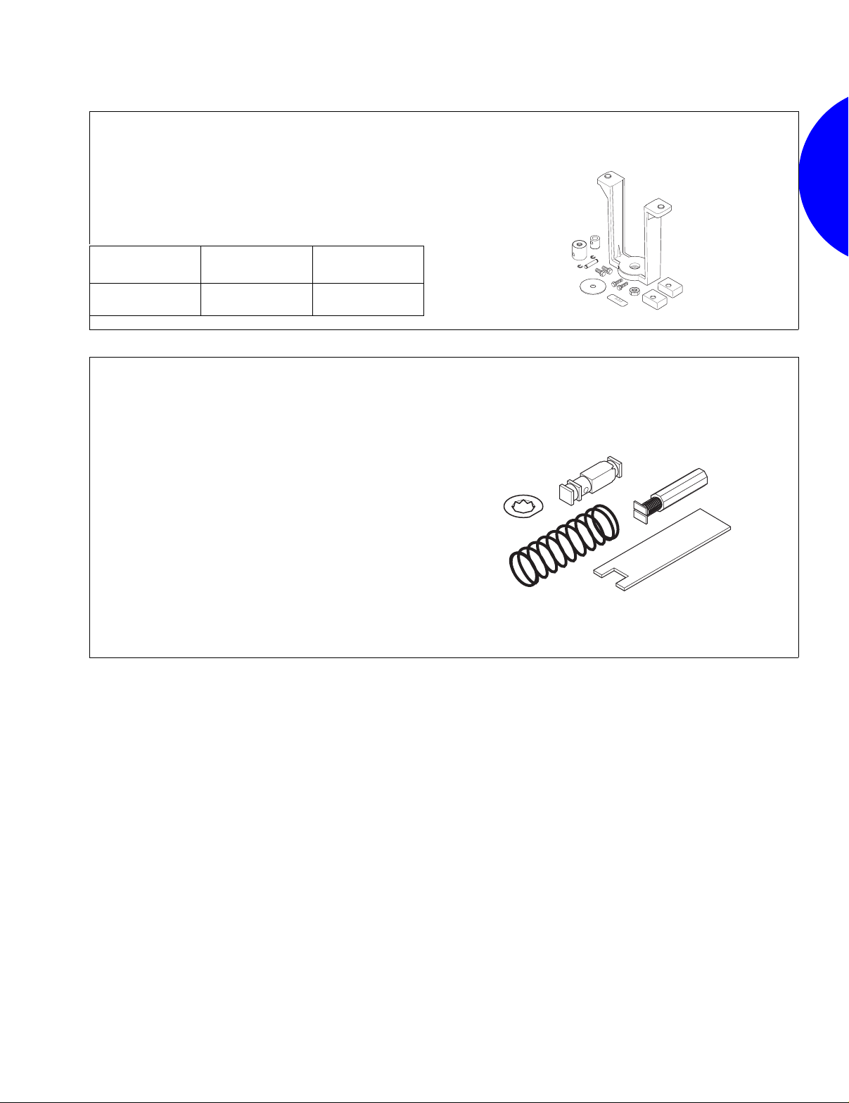
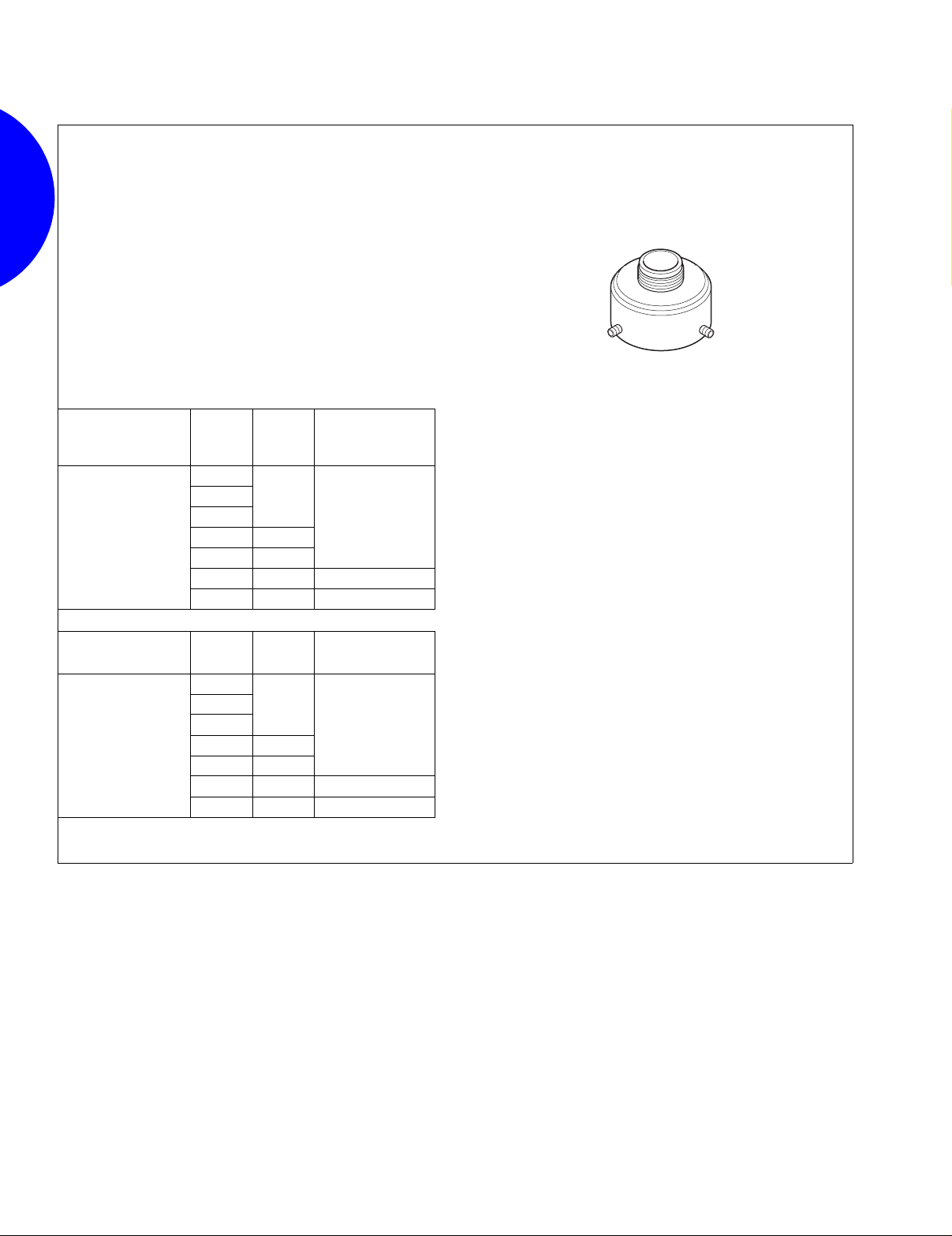
Application
The AV-352 valve linkage is used to field-install gear train
actuators on specified 2-1/2 to 6 in. valve bodies.
Features:
• Compatible with Invensys (Barber-Colman) 2-1/2 to 6 in. valves.
• Provides increased close-off pressure on 2-1/2 to 4 in. valves.
• Required for rated close-off pressure on 5 and 6 in. valves.
Specifications
• Actuator mounting: In any upright position with actuator above
the center line of the valve body.
• Minimum actuator torque required: 220 lb-in.
• Actuator travel required: 180°.
Application
For assembling MP-9000 Series gear train actuators to 4 to
6 in. VB-9213 and VB-9313 valve bodies.
Specifications
• Actuator mounting: In any upright position with actuator above
the center line of the valve body.
AV-352
Gear Train Actuator Valve Linkage
AV-357, AV-358
Electric/Electronic Valve Linkage Kits
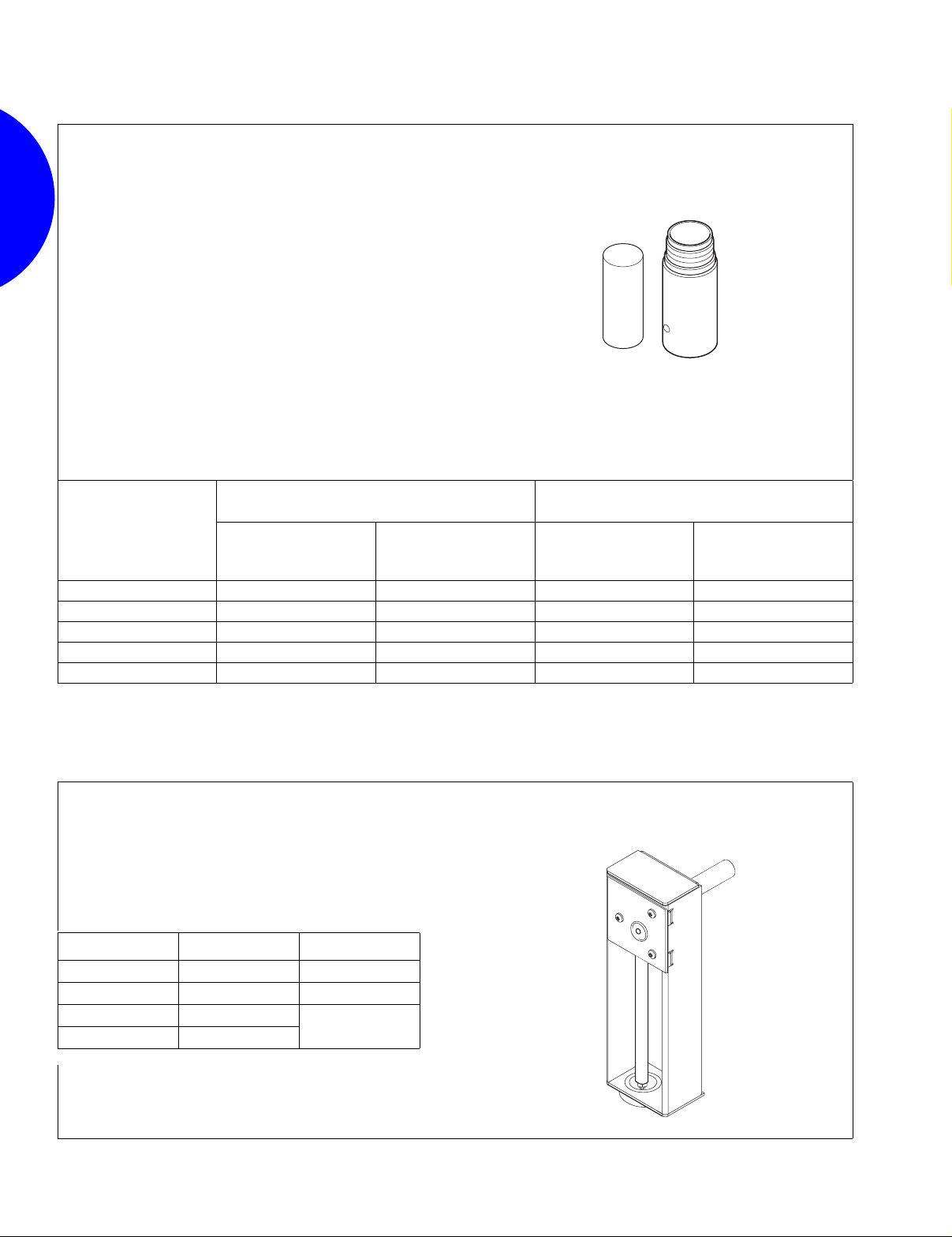
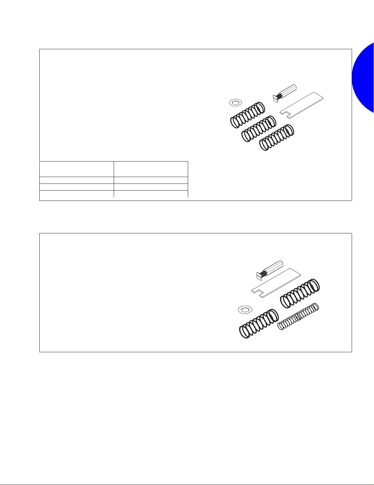
Application
The AV-400 valve linkage kit is used to field-install MK-2690
pneumatic actuators to a variety of 1/2 through 2 in. valve
bodies.
Features:
• Springs are provided for all control signal applications, including
3 to 7, 5 to 10, and 8 to 13 psig.
• Kit fits both current and obsolete Invensys (Barber-Colman)
valve bodies.
• Contains parts for either VB-9XXX or VB-7XXX valve bodies.
Specifications
• Actuator mounting: In any upright position with actuator above
the center line of the valve body.
Spring Range
psig (kPa)
3 to 7 (21 to 46) Yellow
5 to 10 (34 to 69) Black
8 to 13 (55 to 90) Blue
Spring Color
AV-400
Pneumatic Actuator Valve Linkage Kit
858
Page 3
Valve Linkages
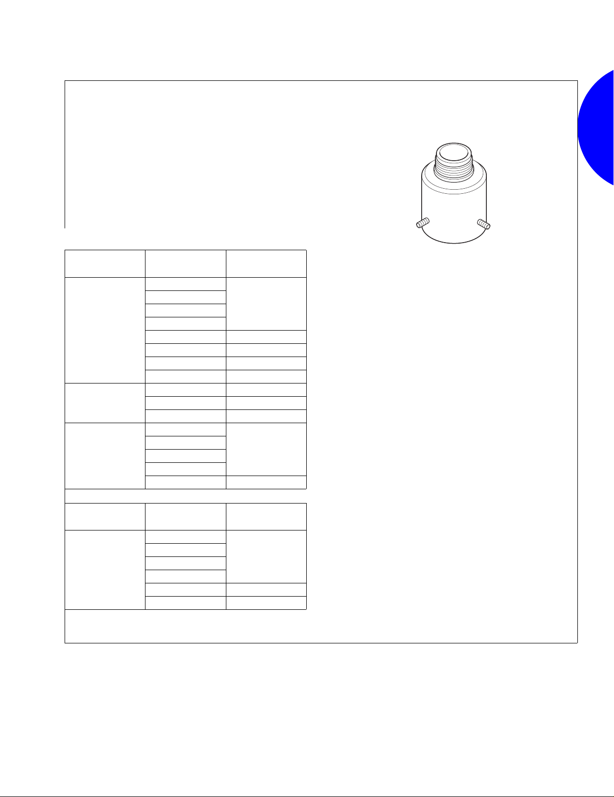
Application
For assembling MK-46XX Series pneumatic actuators to
specific 1/2 to 2 in. VB-7XXX valve bodies.
Specifications
• Actuator mounting: In any upright position with actuator above
the center line of the valve body.
Actuator Effective Area
11 sq. in. (21 cm
2
)
MK-4601 3 to 6 (21 to 41)
MK-4611 5 to 10 (34 to 69)
MK-4621 10 to 13 (69 to 90)
Spring Range
psig (kPa)
Application
For assembling MK-6800 Series 50 sq. in. pneumatic actuators
to 2-1/2 to 6 in. VB-9XXX valve bodies.
For assembling MK-6600 Series 50 sq. in. pneumatic actuators
to 1-1/2 and 2 in. VB-7XXX valve bodies.
Specifications
• Actuator mounting: In any upright position with actuator above
the center line of the valve body.
AV-401
Pneumatic Actuator Valve Linkage Kit
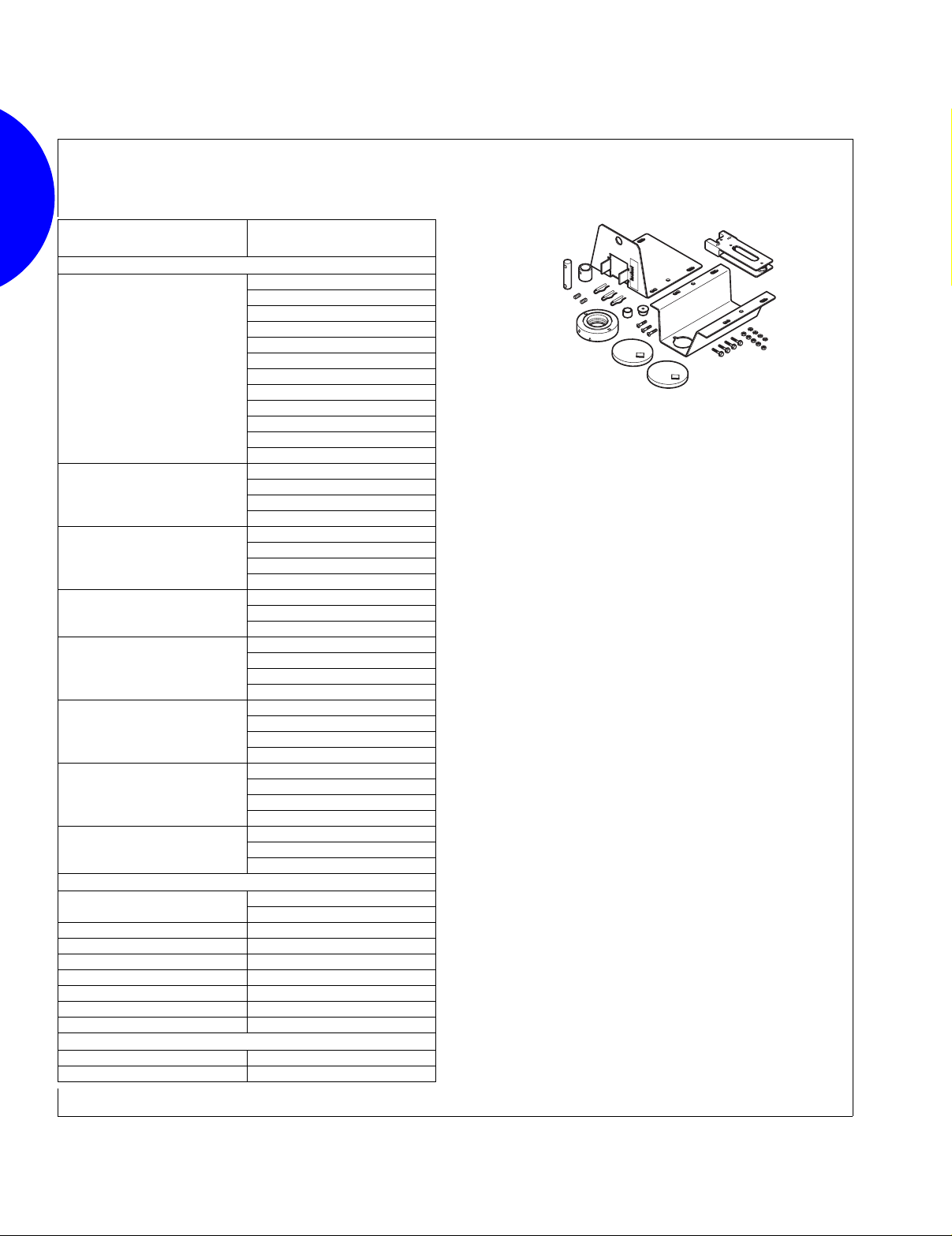
AV-430
Electric/Electronic and Pneumatic
Valve Linkage Kit
Valve Body
Required Parts from AV-430-0-0-1
Description
1-1/2 and 2 in.
(VB-7XXX)
2-1/2 to 4 in.
(VB-202, 252,
304, 804)
1-1/2 to 3 in.
(VB-817)
2-1/2 & 3 in.
Lock
Nut
1/4 in.
3/8 in.
3/8 in.
Stem
Extension
For 1/4 in.
Stem
For 3/8 in.
Stem
For 3/8 in.
a
Stem
Indicator
Plate
With 1/4 in.
Dia. Hole
With 3/8 in.
Dia. Hole
With 3/8 Dia.
(VB-9323)
4 in. (VB-817,
9323)
5 and 6 in.
(VB-817, 9323)
a
Required stem extension may be shipped with valve body.
3/8 in.
3/8 in.
For 3/8 in.
Stem
For 3/8 in.
Stem
With 1/2 in.
Dia. Hole
With 3/8 in.
Dia. Hole
Hole
Scale
Length
1 in.
1 in.
1 in.
1 in.
1-1/2 in.
C
L
O
C
S
L
E
O
D
S
E
D
C
L
O
C
S
L
E
O
D
S
E
D
OPE
O
N
P
EN
C
L
O
C
S
L
E
O
D
S
E
D
O
P
EN
O
P
EN
OPE
OPEN
N
859
Page 4
Valve Linkages
Application
For assembling pneumatic actuators to 2-1/2 to 6 in. valve
bodies.
Specifications
• Actuator mounting: In any upright position with actuator above
the center line of the valve body.
Linkage Number
AV-496 2-1/2 to 6 in.
Valve Body Sizes
Except VB-9323
Actuator
MK-88XX
MK-89XX
Application
For assembling MA-521X, MF-5X13, MP-521X, MP-541X,
MP-551X, MPR-561X, MPR-571X, and MPR-581X Series
hydraulic actuators to (1/2 to 2 in.) VB-7XXX and obsolete VB9XXX valve bodies. Device consists of spring retainer, spring
and combination stem extension and lock nut. TOOL-19 spring
compression tool is recommended for assembly.
Specifications
• Actuator mounting: In any upright position above the center line
of the valve body. For steam applications only, mount the
actuator above the valve body at 45° from vertical.
• Contains parts for either VB-9XXX or VB-7XXX valve bodies.
AV-496
Pneumatic Valve Linkage Kit
C
L
OS
C
L
E
O
D
SE
D
OP
E
O
N
PE
N
AV-600
Electric/Electronic Valve Linkage Kit
860
Page 5
Valve Linkages
Application
The AV-601 valve extension kit is used to increase the
allowable ambient temperature range of MA, MF,
MP-5X1X-XXX, MPR-5X1X and MP-541X Series actuators. The
MF-5X1X, MP-541X, and MPR-5X1X Series of actuators require
the AV-601 extension. This kit provides thermal insulation
between the valve and the actuator. It does not insulate the
actuator from radiant or convective heat transfer.
Electric/Electronic Valve Linkage
Specifications
• Kit consists of an extension coupling and a spacer.
• Dimensions: Add 2-1/32 in. (52 mm) to the “E” dimension for the
valve assembly using an AV-601 linkage extension. Refer to
complete dimensions:
- Two-Way Valves, Union End and Flared.
- Two-Way Valves, Screwed and Flanged.
- Three-Way Mixing and Sequencing Valves, Flared.
- Three-Way Mixing and Diverting Valves, Screwed.
Restrictions on Maximum Ambient Temperature for Valve Actuators
Maximum Ambient T emperature of MF-5X13 , MP-54 1X,
Maximum Temperature of
Media in Valve Body
(Check Rating of Valve)
366 (180) Do Not Use 88 (31) 90 (32) 90 (32)
340 (171) Do Not Use 93 (34) 100 (38) 100 (38)
281 (138) Do Not Use 103 (39) 115 (46) 140 (60)
181 (83) Do Not Use 120 (48) 140 (60)
80 (26)) 140 (60)
a
For detailed valve linkage installation instructs, refer to AV-600 Hydraulic Actuator Valve Linkage Kit General Instructions, F-26279.
b
For detailed valve linkage installation instructs, refer to AV-7600-1 Hydraulic Actuator Valve Linkage Kit General Instructions, F-26235.
c
Maximum allowable ambient temperature of the actuator.
°
F (°C)
a
AV-600
or AV-7600-1b Only
for Chilled Water
Applications Only
or MPR-5X1X)
°
F (°C)
c
AV-600 or AV-7600-1 and
AV-601
140 (60)
°
F (°C)
c
Maximum Ambient Temperature of MA-521X, MP-551X
AV-600 or AV-7600-1 Only
°
F (°C)
140 (60)
or MP-521X
c
c
AV-601
Extension Kit
AV-600 or A V-7600-1 and
°
AV-601
140 (60)
140 (60)
F (°C)
c
c
c
Application
The linkages are designed to link the Invensys actuators to
VB-7XXX globe valves.
Specifications
• Motor mounting: In any upright position with motor above center
line of the valve body.
Actuator Globe Valve SR or NSR
MX40-717X 1-1/2 in. thru 2 in. SR
MX40-6153 1-1/4 in. thru 2 in. NSR
MX40-707X 1 in. thru 2 in.
MX40-715X 1-1/4 in. thru 2 in.
SR
861
AV-602
Globe Valve Linkage Kit
Page 6

Valve Linkages
Application
The AV-603 linkage is designed to link the Invensys MF40-6043
and MS40-6043 actuators to 1/2” through 2”, 2-way or 3-way
globe valves.
Specifications
• Motor mounting: In any upright position with motor above center
line of the valve body.
Application
The AV-605 linkage is designed to link the Invensys MX40-6083
to 1/2” through 2”, 2-way or 3-way globe valves and the MA40704X, MF40-7043, and MS40-7043 actuators to 1/2” through 2”,
2-way or 3-way globe valves.
Specifications
• Motor mounting: In any upright position with motor above center
line of the valve body.
AV-603
Globe Valve Linkage Kit
AV-605
Globe Valve Linkage Kit
Application
For assembling MM/ MMR-400 or MM/ MMR-500 Series
actuators to 1/2 to 2 in. VB-7XXX, 2-1/2 to 4 in. VB-9XXX, and
2-1/2 to 3 in. VB-9323 valve bodies. Refer to table below.
Specifications
• Motor mounting: In any upright position with motor above center
line of the valve body.
Valve Size Linkage
1/2 to 1-1/4 in. AV-630-010
2-1/2 to 4 in. except VB-9323 AV-630-030
2-1/2 and 3 in. VB-9323 AV-630-040
All the above valves AV-630
AV-630
Electric/Electronic Valve Linkage Kit
862
Page 7
Valve Linkages
Application
For assembling MM/ MMR-400 or MM/ MMR-500 Series to
specific Honeywell valve bodies.
Valve Size
2-Way Valves
1/2”
3/4”
1”
1-1/4”
1-1/2”
2”
2-1/2”
3”
3-Way Valves - Mixing
1/2”
3/4” V5013A1021
1” V5013A1039
1-1/4” V5013A1047
1-1/2” V5013A1054
2” V5013A1062
2-1/2” V5013B1003
3” V5013B1011
3-Way Valves - Diverting
2-1/2” V90CA-7
3” V90CA-8
Honeywell Valve Body
Part Number
V5011A1015
V5011A1049
V5011A1072
V5011A1106
V5011C1045
V5011C1060
V5011C1086
V5011C1524
V5011C1532
V5011C1540
V5011C1557
V5011C1565
V5011A1163
V5011C1144
V5011C1151
V5011C1599
V5011A1221
V5011C1201
V5011C1219
V5011C1623
V5011A1288
V5011C1268
V5011C1656
V5011A1346
V5011C1326
V5011C1334
V5011C1680
V5011A1395
V5011A1403
V5011C1383
V5011C1391
V5011A1460
V5011A1734
V5011C1441
V5011C1458
V5011A1528
V5011A1767
V5011C1516
V5013A1005
V5013A1013
AV-631
Electric/Electronic Valve Linkage Kit
863
Page 8
Valve Linkages
Application
For mounting MM-400/500 modular actuator to Honeywell
Q618A and Johnson Y20EBD valve linkages.
The kit is also used to mount Honeywell Q607 auxiliary switch
and Q181A auxiliary potentiometer kits to MM-400/500
modular actuators.
Application
The AV-641 Valve Linkage is designed for mounting MF-22XX3
series Floating Electric and MS-22353 Proportional actuators
onto Invensys series valve bodies.
Features:
• Provides direct couple interface between actuators and valve
bodies.
Specifications
• Actuator mounting: In any upright position with actuator above
the center line of the valve body.
• Also see AV-644 Valve Linkage Kit for hex (center section) stem
extension.
AV-632
Adaptor Kit
AV-641
Valve Linkage Kit
Application
The AV-642 Valve Linkage is designed for mounting MF-22XX3
series Floating Electric and MS-22353 Proportional actuators
onto 15 mm and 20 mm GBX and VT Controlli series valve
bodies.
Features:
• Provides direct couple interface between actuators and Controlli
valve bodies.
Specifications
• Actuator mounting: In any upright position with actuator above
the center line of the valve body.
AV-642
Valve Linkage Kit
864
Page 9

Valve Linkages
Application
The AV-644 Valve Linkage is designed for mounting MF-22XX3
series Floating Electric and MS-22353 Proportional actuators
onto Invensys series valve bodies.
Features:
• Provides direct couple interface between actuators and valve
bodies.
Specifications
• Actuator mounting: In any upright position with actuator above
the center line of the valve body.
• Replaces AV-643 Valve Linkage (plastic).
Note: AV-644-10 includes the drive screw.
Application
Provides the interface between electric gear train actuators
and Honeywell V-5011 two-way and V-5013 three-way (1/2 to
3 in.) valve bodies with 1-3/8 in. bonnets.
Specifications
• Actuator mounting: In any upright position with actuator above
center line of the valve body.
• Minimum actuator torque required: 50 lb-in. (5.6 N-m). Actuator
must have 180° stroke.
• Stem force: 150 lb (667 N).
• Typical actuators:
- MA-318, 318-500, 416, 416-500, 418, 418-500, 419, 419-500.
- MC-351, 421, 431, 4311 and MC5-4311.
- MP-361, 371, 381, 382, 421, 422, 451, 452, 461-600, 465,
471-600, 475, 481-600, 485, 486, 4851.
- MP5-4651, 4751, 4851.
AV-644 and AV-644-10
Valve Linkage Kit
AV-650
Electric/Electronic Valve Linkage Kit
Close-Off Pressure Ratings
Close-Off
Valve Body
1/2 in.
1 in. 1 in.
V-5011
a
1-1/4 in. 132 (910) 1-1/4 in. 137 (945)
1-1/2 in. 85 (586) 1-1/2 in. 92 (634)
2 in. 52 (359) 2 in. 63 (434)
2-1/2 in. 30 (207) 2-1/2 in. 30 (207)
3 in. 19 (131) 3 in. 21 (145)
Based on 1050 lb (668 N) stem force.
Pressure
Ratings
psi (kPa)
150 (1034)
865
a
Valve Body
V-5013
1/2 in.
Close-Off
Pressure
Ratings
psi (kPa)
150 (1034)3/4 in. 3/4 in.
a
Page 10

Valve Linkages
Application
For mounting MF-60000 Series actuators on 1/2- 2 in VB-7000
and VB-9000 valves.
Features:
• Provides direct couple interface between actuator valve.
Specifications
• Actuator mounting: In any upright position with actuator above
the center line of the valve body.
Application
For mounting MF-60000 Series actuators on 2-1/2, 3, or 4 in.
VB-921X and VB-931X valves.
Features:
• Provides direct couple interface between MF-60000 actuator and
2-1/2 to 4 in. valve.
Specifications
• Actuator mounting: In any upright position with actuator above
the center line of the valve body.
AV-671
Electric/Electronic Valve Linkage Kit
AV-672
Electric/Electronic Valve Linkage Kit
866
Page 11
Valve Linkages
Application
For mounting selected Invensys actuators on Johnson
Controls 1/2 through 2 in. VB-3754, VB-3924, and VB-4324
valves.
Features:
• Provides direct couple interface between MF-631X3 actuator
and 1/2 through 2 in. Johnson Controls VB-3754, VB-3924, and
VB-4324 valves.
Specifications
• Actuator mounting: In any upright position with actuator above
the center line of the valve body.
Close-Off Rating
Two-Way Valves
Johnson Controls
Valve Body
VB-3754
(Push Down to Close)
VB-3974
(Push Down to Open)
Three-Way Valves
Johnson Controls
Valve Body
VB-4324
(Three-Way Mixing)
P
Code
-1
-2
-3
-4 3/4
-5 1
-6 1-1/2 95
-7 2 55
P Code
-1
-2
-3
-4 3/4
-5 1
-6 1-1/2 95
-7 2 55
Size
in.
1/2
Size
in.
1/2
MF-631X3
Close-Off Pressure
Ratings psig
150
Close-Off Pressure
Ratings
150
AV-673
Electric/Electronic Valve Linkage Kit
867
Page 12
Valve Linkages
Application
For mounting selected Invensys actuators on 1/2 to 3 in.
Honeywell 3/4 in. stroke valves.
Features:
• Provides direct couple interface between MF-631X3 actuator
and 1/2 to 3 in. Honeywell 3/4 in. stroke valve.
Specifications
• Actuator mounting: In any upright position with actuator above
the center line of the valve body.
Close-Off Rating
Two-Way Valves
Honeywell Valve Bod y
V5011F
(Screwed)
V5011G
(Screwed, Comp. Disc)
V5011G
(Screwed,
Metal-to-Metal Seating)
Three-Way Valves
Honeywell Valve Bod y
V5013F
(Screwed, Mixing)
Size
in.
1/2
3/4
1
1-1/4
1-1/2 123
275
2-1/2 44
327
275
2-1/2 44
327
1/2
3/4
1
1-1/4
1-1/2 123
Size
in.
1/2
3/4
1
1-1/4
1-1/2 137
296
Close-Off Pressure
Ratings psig
150
150
Close-Off Pressure
Ratings psig
150
AV-674
Electric/Electronic Valve Linkage Kit
868
Page 13

Valve Linkages
Application
The AV-680 linkage is used to mount the MS-7913 and
MS-7923 model actuators to 1-1/2 to 2 in. VB-7XXX globe valve
bodies.
Specifications
• Parts needed to mount MX-7913 and MX-7923 actuators to aa
VB-7XXX valves.
• If fluid temperatures exceed 300°F (150°C), mount actuator
above horizontal, but at least 45° from vertical.
Application
The AV-681 linkage is used to mount the MS-7913 and MS-7923
model actuators to 2-1/2 to 4 in. VB-9XXX globe valves.
Specifications
• Parts to mount MX-7913 and MX-7923 actuators to obsolete VB9XXX valves.
• If fluid temperatures exceed 300°F (150°C), mount actuator
above horizontal, but at least 45° from vertical.
AV-680
Electric/Electronic Valve Linkage Kit
AV-681
Electric/Electronic Valve Linkage Kit
Application
The AV-682 linkage is used to mount the MS-7913 and
MS-7923 model actuators to style A and B (obsolete)1-1/2 and
2 in. VB-9XXX valves.
Specifications
• Parts needed to mount MX-7913 and MX-7923 actuators to
obsolete VB-9XXX valves.
• If fluid temperatures exceed 300°F (150°C), mount actuator
above horizontal, but at least 45° from vertical.
869
AV-682
Electric/Electronic Valve Linkage Kit
Page 14
Valve Linkages
Application
The AV-7400 valve linkage kit is used to field-install MK-2690
pneumatic actuators to a variety of VB-7XXX series 1/2
through 2 in. valve bodies.
Features:
• Springs are provided for all control signal applications, including
3 to 7, 5 to 10, and 8 to 13 psig.
• Kit fits all VB-7XXX series valve bodies.
• Blue spring used with AV-7600-1 supports hydraulic 4-20 mA
and 0-10 Vdc applications.
Specifications
• Actuator mounting: In any upright position with actuator above
the center line of the valve body.
Spring Range
psig (kPa)
3 to 7 (21 to 48) Yellow
5 to 10 (34 to 68) Black
8 to 13 (55 to 89) Blue
Spring Color
AV-7400
Pneumatic Actuator Valve Linkage Kit
Application
The AV-7600-1 valve linkage kit is used to field assemble
MA-521X, MF-5X13, MP-521X, MP-541X, MP-551X, MPR-561X,
MPR-571X, and MPR-581X round hydraulic actuators to 1/2
through 2 in. VB-7XXX series valve bodies.
Features:
• Provides direct couple interface between MA, MF, MP, and
MPR-5XXX actuators and valve bodies.
• Kit fits all VB-7XXX series valve bodies.
• Includes spring choices for higher 2-way valve close off.
Specifications
• Actuator mounting: In any upright position above the center line
of the valve body. For steam applications only, mount the
actuator above the valve body at 45° from vertical.
AV-7600-1
Hydraulic Actuator Valve Linkage Kit
870
Page 15

Valve Linkages
871
 Loading...