

Page 1

ModiconTM5
EIO0000003215 09/2020
Modicon TM5
Transmitter and Receiver Modules
Hardware Guide
09/2020
EIO0000003215.01
www.schneider-electric.com
Page 2

The information provided in this documentation contains general descriptions and/or technical
characteristics of the performance of the products contained herein. This documentation is not
intended as a substitute for and is not to be used for determining suitability or reliability of these
products for specific user applications. It is the duty of any such user or integrator to perform the
appropriate and complete risk analysis, evaluation and testing of the products with respect to the
relevant specific application or use thereof. Neither Schneider Electric nor any of its affiliates or
subsidiaries shall be responsible or liable for misuse of the information contained herein. If you
have any suggestions for improvements or amendments or have found errors in this publication,
please notify us.
You agree not to reproduce, other than for your own personal, noncommercial use, all or part of
this document on any medium whatsoever without permission of Schneider Electric, given in
writing. You also agree not to establish any hypertext links to this document or its content.
Schneider Electric does not grant any right or license for the personal and noncommercial use of
the document or its content, except for a non-exclusive license to consult it on an "as is" basis, at
your own risk. All other rights are reserved.
All pertinent state, regional, and local safety regulations must be observed when installing and
using this product. For reasons of safety and to help ensure compliance with documented system
data, only the manufacturer should perform repairs to components.
When devices are used for applications with technical safety requirements, the relevant
instructions must be followed.
Failure to use Schneider Electric software or approved software with our hardware products may
result in injury, harm, or improper operating results.
Failure to observe this information can result in injury or equipment damage.
© 2020 Schneider Electric. All rights reserved.
2 EIO0000003215 09/2020
Page 3

Table of Contents
Safety Information. . . . . . . . . . . . . . . . . . . . . . . . . . . . . . 5
About the Book . . . . . . . . . . . . . . . . . . . . . . . . . . . . . . . . 7
Part I General Overview . . . . . . . . . . . . . . . . . . . . . . . . . . .
Chapter 1 TM5 System General Rules for Implementing . . . . . . . . 13
Installation and Maintenance Requirements . . . . . . . . . . . . . . . . . . . .
Wiring Best Practices . . . . . . . . . . . . . . . . . . . . . . . . . . . . . . . . . . . . .
TM5 Environmental Characteristics. . . . . . . . . . . . . . . . . . . . . . . . . . .
Installation Guidelines . . . . . . . . . . . . . . . . . . . . . . . . . . . . . . . . . . . . .
Hot Swapping Electronic Modules. . . . . . . . . . . . . . . . . . . . . . . . . . . .
Chapter 2 TM5 Transmitter and Receiver General Overview . . . . . 27
General Description. . . . . . . . . . . . . . . . . . . . . . . . . . . . . . . . . . . . . . .
Physical Description . . . . . . . . . . . . . . . . . . . . . . . . . . . . . . . . . . . . . .
Part II TM5 System Transmitter and Receiver Electronic
Modules . . . . . . . . . . . . . . . . . . . . . . . . . . . . . . . . . .
Chapter 3 TM5SBET1 Transmitter Electronic Module . . . . . . . . . . 37
TM5SBET1 Presentation. . . . . . . . . . . . . . . . . . . . . . . . . . . . . . . . . . .
TM5SBET1 Characteristics . . . . . . . . . . . . . . . . . . . . . . . . . . . . . . . . .
TM5SBET1 Wiring Diagram . . . . . . . . . . . . . . . . . . . . . . . . . . . . . . . .
Chapter 4 TM5SBET7 Transmitter Electronic Module . . . . . . . . . . 43
TM5SBET7 Presentation. . . . . . . . . . . . . . . . . . . . . . . . . . . . . . . . . . .
TM5SBET7 Characteristics . . . . . . . . . . . . . . . . . . . . . . . . . . . . . . . . .
TM5SBET7 Wiring Diagram . . . . . . . . . . . . . . . . . . . . . . . . . . . . . . . .
Chapter 5 TM5SBER2 Receiver Electronic Module . . . . . . . . . . . . 49
TM5SBER2 Presentation . . . . . . . . . . . . . . . . . . . . . . . . . . . . . . . . . .
TM5SBER2 Characteristics. . . . . . . . . . . . . . . . . . . . . . . . . . . . . . . . .
TM5SBER2 Wiring Diagram . . . . . . . . . . . . . . . . . . . . . . . . . . . . . . . .
Glossary . . . . . . . . . . . . . . . . . . . . . . . . . . . . . . . . . . . . . . . . .
Index . . . . . . . . . . . . . . . . . . . . . . . . . . . . . . . . . . . . . . . . .
11
14
16
20
23
24
28
31
35
38
41
42
44
46
47
50
53
56
57
61
EIO0000003215 09/2020 3
Page 4

4 EIO0000003215 09/2020
Page 5
Safety Information
Important Information
NOTICE
Read these instructions carefully, and look at the equipment to become familiar with the device
before trying to install, operate, service, or maintain it. The following special messages may appear
throughout this documentation or on the equipment to warn of potential hazards or to call attention
to information that clarifies or simplifies a procedure.
EIO0000003215 09/2020 5
Page 6

PLEASE NOTE
Electrical equipment should be installed, operated, serviced, and maintained only by qualified
personnel. No responsibility is assumed by Schneider Electric for any consequences arising out of
the use of this material.
A qualified person is one who has skills and knowledge related to the construction and operation
of electrical equipment and its installation, and has received safety training to recognize and avoid
the hazards involved.
6 EIO0000003215 09/2020
Page 7
About the Book
At a Glance
Document Scope
This manual describes the hardware implementation of the Modicon TM5 Transmitter and
Receiver modules. It provides parts descriptions, specifications, wiring diagrams, installation and
setup for Modicon TM5 Transmitter and Receiver modules.
Validity Note
This document has been updated for the release of EcoStruxureTM Machine Expert V1.2.5.
Related Documents
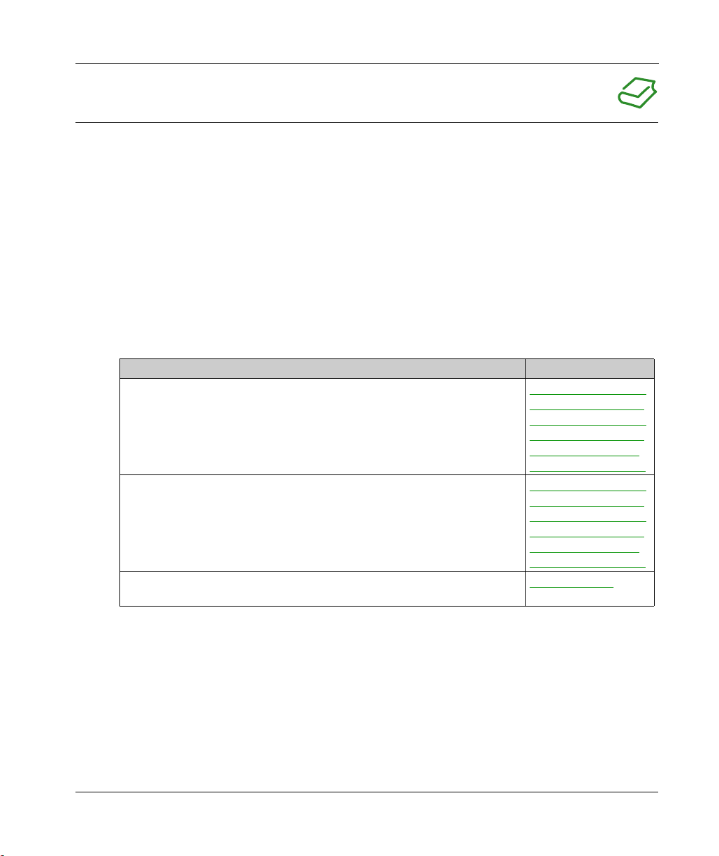
Title of Documentation Reference Number
Modicon TM5 Expansion Modules Configuration Programming Guide
Modicon TM5 / TM7 Flexible System - System Planning and Installation Guide
Communication Electronic Modules TM5 Transmitter and Receiver Instruction
Sheet
EIO0000003179 (ENG)
EIO0000003180 (FRE)
EIO0000003181 (GER)
EIO0000003182 (SPA)
EIO0000003183 (ITA)
EIO0000003184 (CHS)
EIO0000003161 (ENG)
EIO0000003162 (FRE)
EIO0000003163 (GER)
EIO0000003164 (SPA)
EIO0000003165 (ITA)
EIO0000003166 (CHS)
S1A12567(ENG)
You can download these technical publications and other technical information from our website
at https://www.se.com/ww/en/download/ .
EIO0000003215 09/2020 7
Page 8
Product Related Information
HAZARD OF ELECTRIC SHOCK, EXPLOSION OR ARC FLASH
Disconnect all power from all equipment including connected devices prior to removing any
covers or doors, or installing or removing any accessories, hardware, cables, or wires except
under the specific conditions specified in the appropriate hardware guide for this equipment.
Always use a properly rated voltage sensing device to confirm the power is off where and when
indicated.
Replace and secure all covers, accessories, hardware, cables, and wires and confirm that a
proper ground connection exists before applying power to the unit.
Use only the specified voltage when operating this equipment and any associated products.
Failure to follow these instructions will result in death or serious injury.
POTENTIAL FOR EXPLOSION
Only use this equipment in non-hazardous locations, or in locations that comply with Class I,
Division 2, Groups A, B, C and D.
Do not substitute components which would impair compliance to Class I, Division 2.
Do not connect or disconnect equipment unless power has been removed or the location is
known to be non-hazardous.
Do not use the USB port(s), if so equipped, unless the location is known to be non-hazardous.
Failure to follow these instructions will result in death or serious injury.
DANGER
DANGER
8 EIO0000003215 09/2020
Page 9
WARNING
LOSS OF CONTROL
The designer of any control scheme must consider the potential failure modes of control paths
and, for certain critical control functions, provide a means to achieve a safe state during and
after a path failure. Examples of critical control functions are emergency stop and overtravel
stop, power outage and restart.
Separate or redundant control paths must be provided for critical control functions.
System control paths may include communication links. Consideration must be given to the
implications of unanticipated transmission delays or failures of the link.
Observe all accident prevention regulations and local safety guidelines.
Each implementation of this equipment must be individually and thoroughly tested for proper
1
operation before being placed into service.
Failure to follow these instructions can result in death, serious injury, or equipment damage.
1
For additional information, refer to NEMA ICS 1.1 (latest edition), "Safety Guidelines for the
Application, Installation, and Maintenance of Solid State Control" and to NEMA ICS 7.1 (latest
edition), "Safety Standards for Construction and Guide for Selection, Installation and Operation of
Adjustable-Speed Drive Systems" or their equivalent governing your particular location.
WARNING
UNINTENDED EQUIPMENT OPERATION
Only use software approved by Schneider Electric for use with this equipment.
Update your application program every time you change the physical hardware configuration.
Failure to follow these instructions can result in death, serious injury, or equipment damage.
EIO0000003215 09/2020 9
Page 10

10 EIO0000003215 09/2020
Page 11
ModiconTM5
General Overview
EIO0000003215 09/2020
General Overview
Part I
General Overview
What Is in This Part?
This part contains the following chapters:
Chapter Chapter Name Page
1 TM5 System General Rules for Implementing 13
2 TM5 Transmitter and Receiver General Overview 27
EIO0000003215 09/2020 11
Page 12

General Overview
12
EIO0000003215 09/2020
Page 13
ModiconTM5
TM5 System General Rules for Implementing
EIO0000003215 09/2020
TM5 System General Rules for Implementing
Chapter 1
TM5 System General Rules for Implementing
What Is in This Chapter?
This chapter contains the following topics:
Installation and Maintenance Requirements 14
Wiring Best Practices 16
TM5 Environmental Characteristics 20
Installation Guidelines 23
Hot Swapping Electronic Modules 24
Topic Page
EIO0000003215 09/2020 13
Page 14

TM5 System General Rules for Implementing
Installation and Maintenance Requirements
Before Starting
Read and understand this chapter before beginning the installation of your TM5 System.
The use and application of the information contained herein require expertise in the design and
programming of automated control systems. Only you, the user, machine builder or integrator, can
be aware of all the conditions and factors present during installation and setup, operation, and
maintenance of the machine or process, and can therefore determine the automation and
associated equipment and the related safeties and interlocks which can be effectively and properly
used. When selecting automation and control equipment, and any other related equipment or
software, for a particular application, you must also consider any applicable local, regional or
national standards and/or regulations.
Pay particular attention in conforming to any safety information, different electrical requirements,
and normative standards that would apply to your machine or process in the use of this equipment.
NOTICE
ELECTROSTATIC DISCHARGE
Store all components in their protective packaging until immediately before assembly.
Never touch exposed conductive parts such as contacts or terminals.
Failure to follow these instructions can result in equipment damage.
Disconnecting Power
All options and modules should be assembled and installed before installing the control system on
a mounting rail, onto a mounting plate or in a panel. Remove the control system from its mounting
rail, mounting plate or panel before disassembling the equipment.
HAZARD OF ELECTRIC SHOCK, EXPLOSION OR ARC FLASH
Disconnect all power from all equipment including connected devices prior to removing any
covers or doors, or installing or removing any accessories, hardware, cables, or wires except
under the specific conditions specified in the appropriate hardware guide for this equipment.
Always use a properly rated voltage sensing device to confirm the power is off where and when
indicated.
Replace and secure all covers, accessories, hardware, cables, and wires and confirm that a
proper ground connection exists before applying power to the unit.
Use only the specified voltage when operating this equipment and any associated products.
Failure to follow these instructions will result in death or serious injury.
14
DANGER
EIO0000003215 09/2020
Page 15
Programming Considerations
UNINTENDED EQUIPMENT OPERATION
Only use software approved by Schneider Electric for use with this equipment.
Update your application program every time you change the physical hardware configuration.
Failure to follow these instructions can result in death, serious injury, or equipment damage.
Operating Environment
UNINTENDED EQUIPMENT OPERATION
Install and operate this equipment according to the conditions described in the Environmental
Characteristics.
Failure to follow these instructions can result in death, serious injury, or equipment damage.
Installation Considerations
UNINTENDED EQUIPMENT OPERATION
Use appropriate safety interlocks where personnel and/or equipment hazards exist.
Install and operate this equipment in an enclosure appropriately rated for its intended
environment and secured by a keyed or tooled locking mechanism.
Use the sensor and actuator power supplies only for supplying power to the sensors or
actuators connected to the module.
Power line and output circuits must be wired and fused in compliance with local and national
regulatory requirements for the rated current and voltage of the particular equipment.
Do not use this equipment in safety-critical machine functions unless the equipment is
otherwise designated as functional safety equipment and conforming to applicable regulations
and standards.
Do not disassemble, repair, or modify this equipment.
Do not connect any wiring to reserved, unused connections, or to connections designated as
No Connection (N.C.).
Failure to follow these instructions can result in death, serious injury, or equipment damage.
TM5 System General Rules for Implementing
WARNING
WARNING
WARNING
NOTE: JDYX2 or JDYX8 fuse types are UL-recognized and CSA approved.
EIO0000003215 09/2020 15
Page 16
TM5 System General Rules for Implementing
Wiring Best Practices
Introduction
There are several rules that must be followed when wiring the TM5 System.
Wiring Rules
HAZARD OF ELECTRIC SHOCK, EXPLOSION OR ARC FLASH
Disconnect all power from all equipment including connected devices prior to removing any
covers or doors, or installing or removing any accessories, hardware, cables, or wires except
under the specific conditions specified in the appropriate hardware guide for this equipment.
Always use a properly rated voltage sensing device to confirm the power is off where and when
indicated.
Replace and secure all covers, accessories, hardware, cables, and wires and confirm that a
proper ground connection exists before applying power to the unit.
Use only the specified voltage when operating this equipment and any associated products.
Failure to follow these instructions will result in death or serious injury.
The following rules must be applied when wiring the TM5 System:
I/O and communication wiring must be kept separate from the power wiring. Route these 2 types
of wiring in separate cable ducting.
Verify that the operating conditions and environment are within the specification values.
Use proper wire sizes to meet voltage and current requirements.
Use copper conductors only.
Use twisted pair, shielded cables for analog, expert, or fast I/O and TM5 bus signals.
Use twisted pair, shielded cables for encoder, networks and fieldbus (CAN, serial, Ethernet).
Use shielded, properly grounded cables for all analog and high-speed inputs or outputs and
communication connections. If you do not use shielded cable for these connections,
electromagnetic interference can cause signal degradation. Degraded signals can cause the
controller or attached modules and equipment to perform in an unintended manner.
DANGER
16
EIO0000003215 09/2020
Page 17
TM5 System General Rules for Implementing
WARNING
UNINTENDED EQUIPMENT OPERATION
Use shielded cables for all fast I/O, analog I/O and communication signals.
Ground cable shields for all analog I/O, fast I/O and communication signals at a single point
Route communication and I/O cables separately from power cables.
Failure to follow these instructions can result in death, serious injury, or equipment damage.
1
Multipoint grounding is permissible if connections are made to an equipotential ground plane
dimensioned to help avoid cable shield damage in the event of power system short-circuit currents.
Refer to the section Grounding the TM5 System to ground the shielded cables.
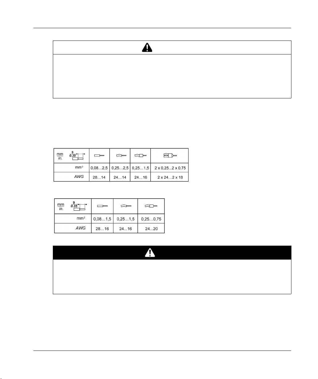
This table provides the wire sizes to use with the removable spring terminal blocks (TM5ACTB06,
TM5ACTB12, TM5ACTB12, TM5ACTB12PS, TM5ACTB32):
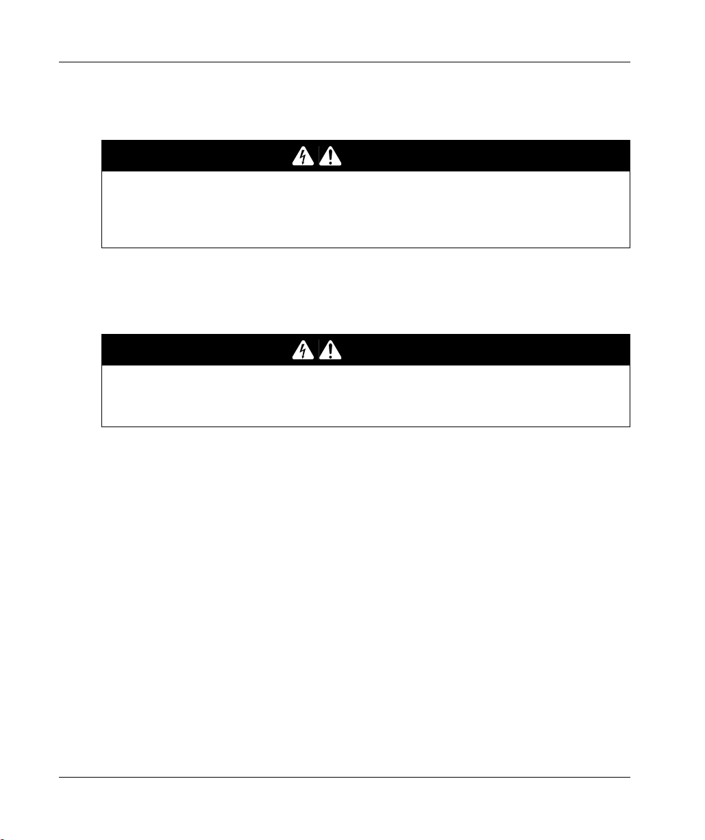
This table provides the wire sizes to use with the TM5ACTB16 terminal blocks:
1
.
DANGER
FIRE HAZARD
Use only the correct wire sizes for the maximum current capacity of the I/O channels and power
supplies.
Failure to follow these instructions will result in death or serious injury.
EIO0000003215 09/2020 17
Page 18
TM5 System General Rules for Implementing
The spring clamp connectors of the terminal block are designed for only one wire or one cable end.
Two wires to the same connector must be installed with a double wire cable end to help prevent
loosening.
LOOSE WIRING CAUSES ELECTRIC SHOCK
Do not insert more than one wire per connector of the spring terminal blocks unless using a
double wire cable end (ferrule).
Failure to follow these instructions will result in death or serious injury.
TM5 Terminal Block
Inserting an incorrect terminal block into the electronic module can cause unintended operation of
the application and/or damage the electronic module.
ELECTRIC SHOCK OR UNINTENDED EQUIPMENT OPERATION
Connect the terminal blocks to their designated location.
Failure to follow these instructions will result in death or serious injury.
DANGER
DANGER
18
NOTE: To help prevent a terminal block from being inserted incorrectly, ensure that each terminal
block and electronic module is clearly and uniquely coded.
EIO0000003215 09/2020
Page 19
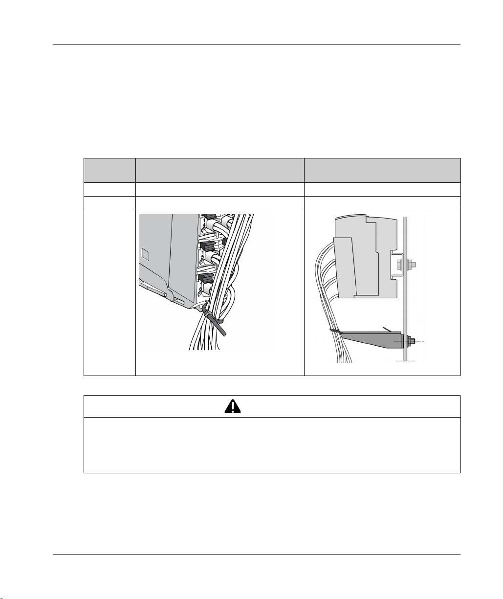
TM5 Strain Relief Using Cable Tie
There are 2 methods to reduce the stress on cables:
The terminal blocks have slots to attach cable ties. A cable tie can be fed through this slot to
secure cables and wires to reduce stress between them and the terminal block connections.
After grounding the TM5 System by means of the grounding plate TM2XMTGB, wires can be
bundled and affixed to the grounding plate tabs using wire ties to reduce stress on the cables.
The following table provides the size of the cable tie and presents the two methods to reduce the
stress on the cables:
TM5 System General Rules for Implementing
Cable Tie
Size
Thickness 1.2 mm (0.05 in.) maximum 1.2 mm (0.05 in.)
Width 4 mm (0.16 in.) maximum 2.5...3 mm (0.1...0.12 in.)
Mounting
illustration
Terminal Block TM2XMTGB Grounding Plate
WARNING
ACCIDENTAL DISCONNECTION FROM PROTECTIVE GROUND (PE)
Do not use the TM2XMTGB Grounding Plate to provide a protective ground (PE).
Use the TM2XMTGB Grounding Plate only to provide a functional ground (FE).
Failure to follow these instructions can result in death, serious injury, or equipment damage.
EIO0000003215 09/2020 19
Page 20
TM5 System General Rules for Implementing
TM5 Environmental Characteristics
Enclosure Requirements
TM5 components are designed as Zone B, Class A industrial equipment according to IEC/CISPR
Publication 11. If they are used in environments other than those described in the standard, or in
environments that do not meet the specifications in this manual, your ability to meet
electromagnetic compatibility requirements in the presence of conducted and/or radiated
interference may be reduced.
The TM5 components meet European Community (CE) requirements for open equipment as
defined by EN61131-2. You must install them in an enclosure designed for the specific
environmental conditions and to minimize the possibility of unintended contact with hazardous
voltages. The enclosure should be constructed of metal to improve the electromagnetic immunity
of your TM5 System. The enclosure should, and in the case of UL compliance, must, have a keyed
locking mechanism to minimize unauthorized access.
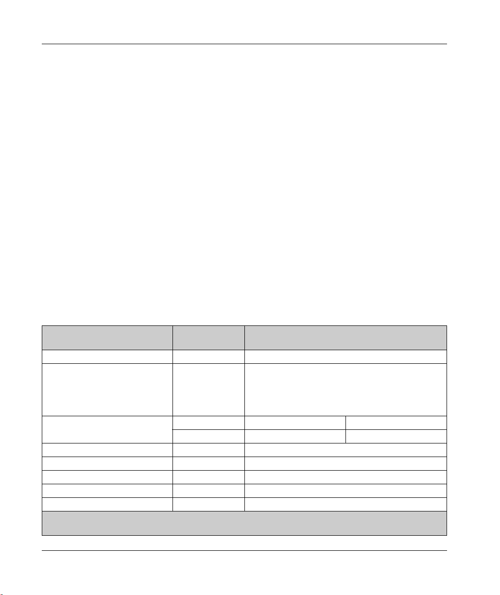
Environmental Characteristics
This equipment meets UL and CSA standards and, for the majority of the modules, carry both
certification marks. In addition, all modules are certified as CE compliant. This equipment is
intended for use in a Pollution Degree 2 industrial environment.
NOTE: Some module characteristics may differ from those presented in the following tables. Refer
to the chapter concerning your specific module for more information.
The table below provides the general environmental characteristics:
Characteristic Minimum
Specification
Standard IEC61131-2 –
Agency Standards UL 508
CSA 22.2 No. 142M1987
CSA 22.2 No. 213M1987
Ambient operating temperature – Horizontal installation 0...55 °C (32...131 °F)
– Vertical installation 0...50 °C (32...122 °F)
Storage temperature – -25...70 °C (-13...158 °F)
Relative humidity – 5...95% (non-condensing)
Degree of pollution IEC60664 2
Degree of protection IEC61131-2 IP20
Corrosion immunity None –
Tested Range
–
NOTE: The tested ranges may indicate values beyond that of the IEC Standard. However, our internal standards
define what is necessary for industrial environments. In all cases, we uphold the minimum specification if indicated.
20
EIO0000003215 09/2020
Page 21

TM5 System General Rules for Implementing
Characteristic Minimum
Tested Range
Specification
Operating altitude – 0...2000 m (0...6.560 ft.)
Storage altitude – 0...3000 m (0...9.842 ft.)
Vibration resistance – Mounted on a DIN rail 3.5 mm (0.138 in.) fixed
amplitude from 5...8.4 Hz
2
9.8 m/s
(1 gn) fixed
acceleration from
8.4...150 Hz
Mechanical shock resistance –
Connection type Removable
––
147 m/s
2
(15 gn) for a duration of 11 ms
spring terminal
block
Connector insertion/removal cycles – 50
NOTE: The tested ranges may indicate values beyond that of the IEC Standard. However, our internal standards
define what is necessary for industrial environments. In all cases, we uphold the minimum specification if indicated.
Electromagnetic Susceptibility
The following table provides the TM5 System electromagnetic susceptibility specifications:
Characteristic Minimum Specification Tested Range
Electrostatic discharge IEC/EN 61000-4-2 8 kV (air discharge), criteria B
4 kV (contact discharge), criteria B
Electromagnetic fields IEC/EN 61000-4-3 10 V/m (80 MHz...2 GHz), criteria A
10 V/m (80 MHz...2.7 GHz)
Fast transients burst IEC/EN 61000-4-4 Power lines: 2 kV, criteria B
I/O: 1 kV, criteria B
Shielded cable: 1 kV, criteria B
Repetition rate: 5 and 100 KHz
Surge immunity 24 Vdc circuit IEC/EN 61000-4-5 1 kV in common mode, criteria B
0.5 kV in differential mode, criteria B
Surge immunity 230 Vac circuit IEC/EN 61000-4-5 2 kV in common mode, criteria B
1 kV in differential mode, criteria B
Induced electromagnetic field IEC/EN 61000-4-6 10 V
(0.15...80 MHz), criteria A
eff
Criteria A Uninterrupted operation during test.
Criteria B Brief interruption during the test allowed.
(1) Applies for TM5SE1IC20005 and TM5SE1MISC20005.
(1)
NOTE: The tested ranges may indicate values beyond that of the IEC Standard. However, our internal standards
define what is necessary for industrial environments. In all cases, we uphold the minimum specification if indicated.
EIO0000003215 09/2020 21
Page 22

TM5 System General Rules for Implementing
Characteristic Minimum Specification Tested Range
Conducted emission EN 55011 (IEC/CISPR11) 150...500 kHz, quasi peak 79 dB (µV)
500 kHz...30 MHz, quasi peak 73 dB (µV)
Radiated emission EN 55011 (IEC/CISPR11) 30...230 MHz, 10 m@40 dB (µV/m)
230 MHz...1 GHz, 10 m@47 dB (µV/m)
Criteria A Uninterrupted operation during test.
Criteria B Brief interruption during the test allowed.
(1) Applies for TM5SE1IC20005 and TM5SE1MISC20005.
NOTE: The tested ranges may indicate values beyond that of the IEC Standard. However, our internal standards
define what is necessary for industrial environments. In all cases, we uphold the minimum specification if indicated.
22
EIO0000003215 09/2020
Page 23

Installation Guidelines
Installation
The following table provides documentation references for spacing requirements and installation
of electronic modules and accessories:
Spacing requirement For mounting positions and minimum clearances, the electronic modules are
Electronic modules
installation
Accessories installation Refer to the
TM5 System General Rules for Implementing
mounted according to the rules defined for the controllers. Refer to the
the TM5 System
Refer to:
TM5 Association Table
Expanding the TM5 System
.
.
.
Installation of Accessories
.
Enclosing
EIO0000003215 09/2020 23
Page 24

TM5 System General Rules for Implementing
Hot Swapping Electronic Modules
Definition
Hot swapping is the ability to remove an I/O electronic module from its bus base and then replace
it with an identical electronic module while the TM5 System is under power without disrupting the
normal operations of the controller. When the electronic module is returned to its bus base or
replaced with another electronic module with the same reference, it starts to operate again.
Hot Swapping Considerations
Before initiating a hot swap operation, confirm that the electronic module type is approved for hot
swapping
(see page 26)
When removing or inserting an I/O module while power is applied, remove and insert the electronic
module by hand. Do not use tools to hot swap modules because they may come into contact with
hazardous voltages. Also, remove any locking clips and the terminal block before removing the
electronic module from its bus base. Hot swapping is only allowed when replacing identical
electronic modules.
EXPLOSION OR ELECTRIC SHOCK
Only perform a hot swap operation in locations known and confirmed to be non-hazardous.
Use only your hands.
Do not use any metal tools.
Do not disconnect any wires from the terminal block.
Only replace an electronic module with an identical reference.
Failure to follow these instructions will result in death or serious injury.
.
DANGER
24
NOTE: Only the electronic module is hot swap-able. Do not attempt a hot swap operation on the
bus base, or on electronic modules that are integrated with their bus bases such as the compact
I/O.
You need to understand and plan for the effects of hot-swapping certain modules. Hot-swapping
modules that control power distribution to other modules, for example, can impact your machine or
process. Power Distribution modules, Interface Power Distribution Modules, Common Distribution
modules, Field Bus Interface Modules, and Transmitter and Receiver modules all either distribute
power or communications to other electronic modules. Disconnecting the connector to these
modules will interrupt power or communications to the modules they service.
For example, some Power Distribution Modules (PDMs) provide power to both the TM5 power bus
and 24 Vdc I/O power segment. It is possible that you may need to replace the PDM because one
service is inoperable, but not both. In this case, hot-swapping the PDM would interrupt the service
that is still operating, and would interrupt power to the modules drawing power from that service.
EIO0000003215 09/2020
Page 25

TM5 System General Rules for Implementing
I/O configurations that employ Common Distribution modules require careful consideration when
wiring is restricted by short wire lengths. It may be the case that in order to hot-swap an electronic
module that has become inoperable, you need to disconnect the connector of the Common module
servicing it. Further, that same Common module may be connected to modules or devices other
than the module you wish to hot-swap. Disconnecting the Common module in this case would
necessarily interrupt the supply to the unaffected modules and/or devices. Be sure that you know
what I/O slices or devices are connected to the Common module, and the impact that this
disconnection would have on your machine or process before attempting a hot-swap operation.
WARNING
LOSS OF CONTROL
The designer of any control scheme must consider the potential failure modes of control paths
and, for certain critical control functions, provide a means to achieve a safe state during and
after a path failure. Examples of critical control functions are emergency stop and overtravel
stop, power outage and restart.
Separate or redundant control paths must be provided for critical control functions.
System control paths may include communication links. Consideration must be given to the
implications of unanticipated transmission delays or failures of the link.
Observe all accident prevention regulations and local safety guidelines.
Each implementation of this equipment must be individually and thoroughly tested for proper
operation before being placed into service.
Failure to follow these instructions can result in death, serious injury, or equipment damage.
1
1
For additional information, refer to NEMA ICS 1.1 (latest edition), "Safety Guidelines for the
Application, Installation, and Maintenance of Solid State Control" and to NEMA ICS 7.1 (latest
edition), "Safety Standards for Construction and Guide for Selection, Installation and Operation of
Adjustable-Speed Drive Systems" or their equivalent governing your particular location.
NOTE: Be sure you thoroughly understand the effects of a hot-swap operation on all modules and
connected devices as they relate to your machine or process.
EIO0000003215 09/2020 25
Page 26

TM5 System General Rules for Implementing
Modules that are not Hot Swap-able
Electronic modules that can not be hot swapped under any circumstances include:
TM5 Electronic Modules Type Reasons
Controller PCI communication The replacement of the PCI communication module
Controller Power Distribution
Module
Embedded I/O Modules
Field bus
interface
Compact I/O I/O modules These modules are not removable.
CANopen interface module The replacement of the CANopen interface module
requires a power cycle before it will recognized by the
controller.
These modules are not removable.
depends on CANopen master architecture. Refer to the
Generic CANopen Implementation Guide and
documentation associated with the CANopen master.
26
EIO0000003215 09/2020
Page 27

ModiconTM5
TM5 Transmitter and R eceiver General O verview
EIO0000003215 09/2020
TM5 Transmitter and R eceiver General O verview
Chapter 2
TM5 Transmitter and Receiver General Overview
Overview
This chapter is an overview of the TM5 transmitter and receiver electronic modules.
What Is in This Chapter?
This chapter contains the following topics:
General Description 28
Physical Description 31
Topic Page
EIO0000003215 09/2020 27
Page 28
TM5 Transmitter and Receiver General Overview
General Description
Overview
The TM5 System provides a virtual rack system through a decentralized backplane. The
decentralized backplane contains a local configuration and several remote configurations
connected together using specific expansion bus cables. The TM5 Transmitter and Receiver
electronic modules handle the communication between remote electronic modules via expansion
bus cables.
The TM5 Transmitter and Receiver electronic modules need to be associated with a bus base and
a terminal block.
Remote Island Features
The following table gives information about the TM5 Transmitter and Receiver used in the TM5
System:
Reference Description
TM5SBET1
(see page 38)
TM5SBET7
(see page 43)
TM5SBER2
(see page 50)
TCSXCNNXNX100 Expansion bus cable.
Transmits the TM5 data bus.
Transmits the TM7 data bus and provides the TM7 power bus to
the TM7 expansion I/O blocks.
Receives the TM5 data bus, provides power to the 24 Vdc I/O
power segment and provides the TM5 power bus to the TM5
expansion I/O blocks.
28
EIO0000003215 09/2020
Page 29

Cable Characteristics
The TM5 cable used between Transmitter and Receiver modules is the TCSXCNNXNX100 cable,
measuring approximately 100 m (328.1 ft). The cable contains two sets of twisted shielded pairs
to limit the electromagnetic interference from the power wires to the DATA signal wires. Both pairs
are shielded with a common tinned copper foil with an additional drain wire.
The following table describes the characteristics of the individual wire pairs of the cable:
Wire Characteristic Value
Pair A Conductor cross section (gauge) 0.34 mm² (22 AWG)
Pair B Conductor cross section (gauge) 0.2 mm² (24 AWG)
The following table lists the description of the individual wire pairs of the cable:
Wire Description Color
Pair A TM5 Power Bus + 5 Vdc (used only for
Pair B TM5 DATA high White
TM5 Transmitter and Receiver General Overview
Linear resistance 55 Ω/km
Linear resistance 90 Ω/km
Characteristic impedance 120 Ω
Red
TM5 IP20 towards TM7 IP67)
TM5 Power Bus 0 Vdc (TM5 bus ref.) Black
TM5 DATA low Blue
The following table lists the general characteristics of the cable:
Characteristic Description
Shield Tinned copper foil and drain wire
Sheath color grey
Operating temperature -10 ... +80 °C (14 ... 176 °F)
Storage temperature -25 ... +80 °C (-13 ... 176 °F
Overall diameter 7.4 mm (0.29 in.) ± 0.2 mm (0.007 in.)
Minimum curve radius - fixed applications 67 mm (2.63 in.)
Fire retardant IEC 60332-1
Low smoke VDE 0207-24
Zero halogen EN50290-2-27
EIO0000003215 09/2020 29
Page 30

TM5 Transmitter and Receiver General Overview
(1)
(2) (2)
TM5SBER2
TM5SBER2TM5SBET1
Implementation of TM5 Transmitter and Receiver Electronic Modules
The maximum distance between a Transmitter and a Receiver is 100 m (328.1 ft). The maximum
overall distance between the beginning of the local configuration containing a Transmitter and the
end of the last remote configuration containing a Receiver is 2500 m (8202.1 ft). The TM5 twistedpair cable (TCSXCNNXNX100) is required to obtain the maximum distance, the proper
electromagnetic resistance and performance required for the communication between Transmitter
and Receiver. In addition, the cable must be properly grounded to the functional ground (FE) of
your TM5 System.
The following picture presents the TM5 System divided into a local configuration and remote
configuration:
LMC058
TM258
TM258LF42DT
EthMAC Address : xx-xx-xx-xx-xx-xx
USB Host
MBS COM
CAN0 STS
CAN1 STS
Host
Pgr Port
MBS
RS485 / RS232
Eth LA
Eth ST
Eth NS
BATTERY (RTC)
PULL
PULL
RUN / MS
BATTERY
APP0
APP1
112
1
122
2
132
3
142
4
152
Ethernet
162
5
6
112
122
132
142
152
162
112
1
122
2
132
3
142
4
152
5
162
6
TM5SBET1
112
112
1
1
122
122
2
2
132
132
3
3
142
142
4
4
152
152
5
5
162
162
6
6
112
1
1
122
2
2
132
3
3
142
4
152
5
162
6
(3) TCSXCNNXNX100
4
l ≤ 100 m (328.1 ft)
5
6
30
1
112
112
122
132
142
152
162
1
122
2
132
3
142
4
152
5
162
6
112
112
121
1
122
2
132
3
142
4
152
5
162
6
112
1
1
1
122
122
122
2
2
2
2
132
132
132
3
3
142
142
4
4
152
152
5
5
162
162
6
6
(3) TCSXCNNXNX100
3
3
l ≤ 100 m (328.1 ft)
142
4
4
152
5
5
162
6
6
112
122
132
142
152
162
112
112
112
1
1
1
2
3
4
5
6
122
132
142
152
162
1
122
122
2
2
2
132
132
3
3
3
142
142
4
4
4
152
152
5
5
5
162
162
6
6
6
(1) Local Configuration
(2) Remote I/O Island Configurations
(3) Expansion bus cable TCSXCNNXNX100
NOTE: For more information to configure Transmitter and Receiver electronic modules refer to
Modicon TM5 Expansion Modules Configuration Programming Guide
.
EIO0000003215 09/2020
Page 31

Physical Description
Introduction
Each slice consists of three elements. These elements are the bus base, the electronic module and
the terminal block.
Elements
The following illustration shows the elements of a slice.
1 Bus base
2 Electronic module
3 Terminal block
TM5 Transmitter and Receiver General Overview
When assembled the three components form an integral unit that resists vibration and electrostatic
discharge.
NOTICE
ELECTROSTATIC DISCHARGE
Never touch the contacts of the electronic module.
Always keep the connector in place during normal operation.
Failure to follow these instructions can result in equipment damage.
EIO0000003215 09/2020 31
Page 32

TM5 Transmitter and Receiver General Overview
Dimensions
The following illustration shows the dimensions of a slice:
Pin Assignment
The following illustration shows the pin assignments respectively for the 6-pin, 12-pin and the 16pin terminal blocks:
32
EIO0000003215 09/2020
Page 33

Accessories
Refer to the
Labeling
Refer to the
Installation of Accessories
Labeling the
TM5 System.
TM5 Transmitter and Receiver General Overview
.
EIO0000003215 09/2020 33
Page 34

TM5 Transmitter and Receiver General Overview
34
EIO0000003215 09/2020
Page 35

ModiconTM5
TM5 System Transmitter and Receiver Electronic Modules
EIO0000003215 09/2020
TM5 System Transmitter and Receiver Electronic Modules
Part II
TM5 System Transmitter and Receiver Electronic Modules
What Is in This Part?
This part contains the following chapters:
Chapter Chapter Name Page
3 TM5SBET1 Transmitter Electronic Module 37
4 TM5SBET7 Transmitter Electronic Module 43
5 TM5SBER2 Receiver Electronic Module 49
EIO0000003215 09/2020 35
Page 36

TM5 System Transmitter and Receiver Electronic Modules
36
EIO0000003215 09/2020
Page 37

ModiconTM5
TM5SBET1 Transmitter Electronic Module
EIO0000003215 09/2020
TM5SBET1 Transmitter Electronic Module
Chapter 3
TM5SBET1 Transmitter Electronic Module
What Is in This Chapter?
This chapter contains the following topics:
TM5SBET1 Presentation 38
TM5SBET1 Characteristics 41
TM5SBET1 Wiring Diagram 42
Topic Page
EIO0000003215 09/2020 37
Page 38

TM5SBET1 Transmitter Electronic Module
TM5SBET1 Presentation
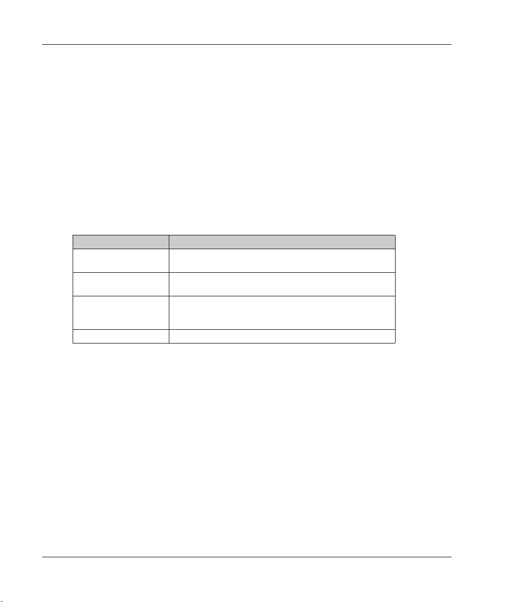
Main Characteristics
The table below describes the main characteristics of the TM5SBET1 electronic module:
Main Characteristics
Function Transmits the TM5 data bus.
Maximum bus length 2500 m (8202.1 ft)
Maximum cable distance between Transmitter
and Receiver
Power distribution No
Ordering Information
The following figure and table give the references to create a slice with the TM5SBET1 electronic
module:
100 m (328.1 ft)
38
NOTICE
ELECTROSTATIC DISCHARGE
Install a right bus base locking plate to the rightmost slice of all configurations.
Install a left bus base locking plate to the first slice of all remote configurations.
Failure to follow these instructions can result in equipment damage.
EIO0000003215 09/2020
Page 39
TM5SBET1 Transmitter Electronic Module
x
SBET1
Number Model Number Description Color
1 TM5ACBM11
or
TM5ACBM15
2 TM5SBET1 Electronic module White
3TM5ACTB06
or
TM5ACTB12
Bus base
Bus base with address
setting
Terminal block, 6 pins
Terminal block, 12 pins
White
White
White
White
NOTE: For more information, refer to
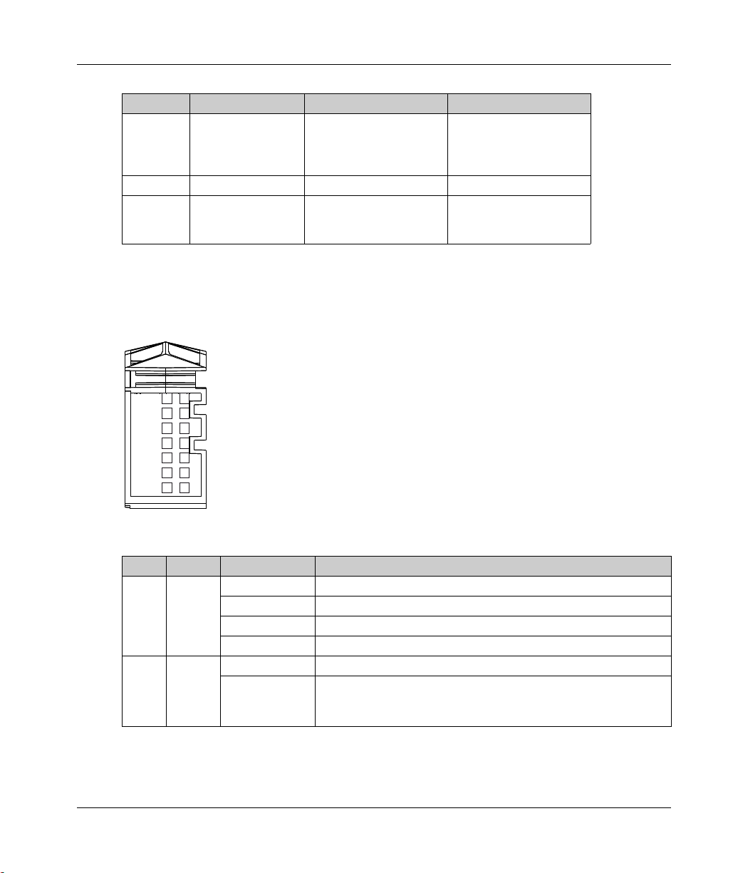
Status LEDs
The following figure shows the status LEDs for TM5SBET1:
The table describes the TM5SBET1 status LEDs:
LED Color Status Description
r Green Off No power supply
e Red Off OK or no power supply
TM5 bus bases and terminal blocks
r
e
Single flash Reset state
Flashing Preoperational state
On Normal state
Double flash Indicates one of the following conditions:
Voltage from the 24 Vdc I/O power segment is too low
Voltage for the TM5 power bus is too low
.
EIO0000003215 09/2020 39
Page 40

TM5SBET1 Transmitter Electronic Module
LED Color Status Description
e+r Steady red / single green
flash
X Yellow Off No communication on the TM5 data bus
On TM5 data bus communication in progress
Invalid firmware
40
EIO0000003215 09/2020
Page 41

TM5SBET1 Characteristics
Introduction
The TM5SBET1 is a data transmitter electronic module. Refer to the environmental specifications
(see page 20)
FIRE HAZARD
Use only the correct wire sizes for the maximum current capacity of the I/O channels and power
supplies.
Failure to follow these instructions will result in death or serious injury.
UNINTENDED EQUIPMENT OPERATION
Do not exceed any of the rated values specified in the environmental and electrical characteristics
tables.
Failure to follow these instructions can result in death, serious injury, or equipment damage.
.
TM5SBET1 Transmitter Electronic Module
DANGER
WARNING
General Characteristics
The table below describes the general characteristics of the TM5SBET1 electronic module:
General Characteristics
Rated power supply voltage 24 Vdc
Power supply range 20.4...28.8 Vdc
24 Vdc I/O segment current draw 25 mA
TM5 power bus current draw 100 mA
Power dissipation 1.10 W max.
Weight 25 g (0.9 oz)
ID code for firmware update 7106 dec
EIO0000003215 09/2020 41
Page 42

TM5SBET1 Transmitter Electronic Module
(2)
c +24 V
0 V
(3)
TM5 Bus Data
TM5 Bus Ref
TM5 Bus Data
(1)
1
1
2
1
1
2
2
2
2
3
2
4
2
6
2
5
1
3
1
4
1
5
1
6
TM5SBET1 Wiring Diagram
Wiring Diagram
The following figure shows the wiring diagram for the TM5SBET1:
(1) Internal electronics
(2) 24 Vdc I/O power segment integrated into the bus bases
(3) TM5 expansion bus cable (TCSXCNNXNX100)
WARNING
UNINTENDED EQUIPMENT OPERATION
Properly ground the cable shields as indicated in the related documentation.
Failure to follow these instructions can result in death, serious injury, or equipment damage.
UNINTENDED EQUIPMENT OPERATION
Do not connect wires to unused terminals and/or terminals indicated as “No Connection (N.C.)”.
Failure to follow these instructions can result in death, serious injury, or equipment damage.
42
WARNING
EIO0000003215 09/2020
Page 43

ModiconTM5
TM5SBET7 Transmitter Electronic Module
EIO0000003215 09/2020
TM5SBET7 Transmitter Electronic Module
Chapter 4
TM5SBET7 Transmitter Electronic Module
What Is in This Chapter?
This chapter contains the following topics:
TM5SBET7 Presentation 44
TM5SBET7 Characteristics 46
TM5SBET7 Wiring Diagram 47
Topic Page
EIO0000003215 09/2020 43
Page 44

TM5SBET7 Transmitter Electronic Module
TM5SBET7 Presentation
Main Characteristics
The table below describes the main characteristics of the TM5SBET7 electronic module:
Main Characteristics
Function Transmits the TM7 data bus and provides the TM7
Maximum bus length 2500 m (8202.1 ft)
Maximum cable distance between
Transmitter and Receiver
Power distribution TM7 power bus
Ordering Information
The following figure and table give the references to create a slice with the TM5SBET7 electronic
module:
power bus to the TM7 expansion I/O blocks.
100 m (328 ft)
44
NOTICE
ELECTROSTATIC DISCHARGE
Install a right bus base locking plate to the rightmost slice of all configurations.
Install a left bus base locking plate to the first slice of all remote configurations.
Failure to follow these instructions can result in equipment damage.
EIO0000003215 09/2020
Page 45
TM5SBET7 Transmitter Electronic Module
Number Model Number Description Color
1 TM5ACBM11
or
TM5ACBM15
2 TM5SBET7 Electronic module White
3 TM5ACTB12 Terminal block, 12 pins White
Bus base
Bus base with address
setting
White
White
NOTE: For more information, refer to
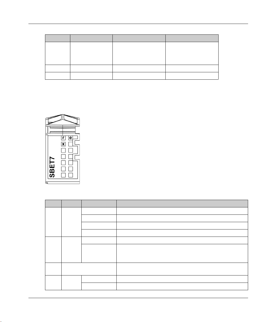
Status LEDs
The following figure shows the status LEDs for TM5SBET7:
The table describes the TM5SBET7 status LEDs:
LED Color Status Description
r Green Off No power supply
e Red Off OK or no power supply
e+r Steady red / single green
X Yellow Off No communication on the TM7 data bus
flash
TM5 bus bases and terminal blocks
Single flash Reset state
Flashing Preoperational state
On Operational state
Double flash Indicates one of the following conditions:
Voltage from the 24 Vdc I/O power segment is too low
Voltage for the TM7 power bus is too low
Invalid firmware
On TM7 data bus communication in progress
.
EIO0000003215 09/2020 45
Page 46
TM5SBET7 Transmitter Electronic Module
TM5SBET7 Characteristics
Introduction
TheTM5SBET7 is a data transmitter electronic module. Refer to the environmental specifications
(see page 20)
FIRE HAZARD
Use only the correct wire sizes for the maximum current capacity of the I/O channels and power
supplies.
Failure to follow these instructions will result in death or serious injury.
UNINTENDED EQUIPMENT OPERATION
Do not exceed any of the rated values specified in the environmental and electrical characteristics
tables.
Failure to follow these instructions can result in death, serious injury, or equipment damage.
.
DANGER
WARNING
General Characteristics
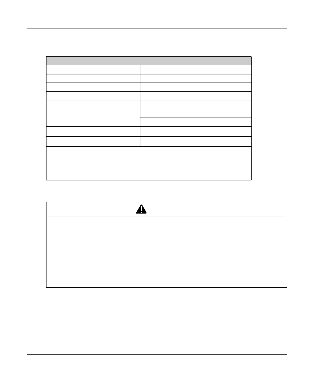
The table below describes the general characteristics of the TM5SBET7 electronic module:
General Characteristics
Rated power supply voltage 24 Vdc
Power supply range 20.4...28.8 Vdc
24 Vdc I/O segment current draw 25 mA
TM5 power bus current draw 100 mA
Power dissipation 1.10 W max.
Weight 25 g (0.9 oz)
ID code for firmware update 41528 dec
46
EIO0000003215 09/2020
Page 47
TM5SBET7 Wiring Diagram
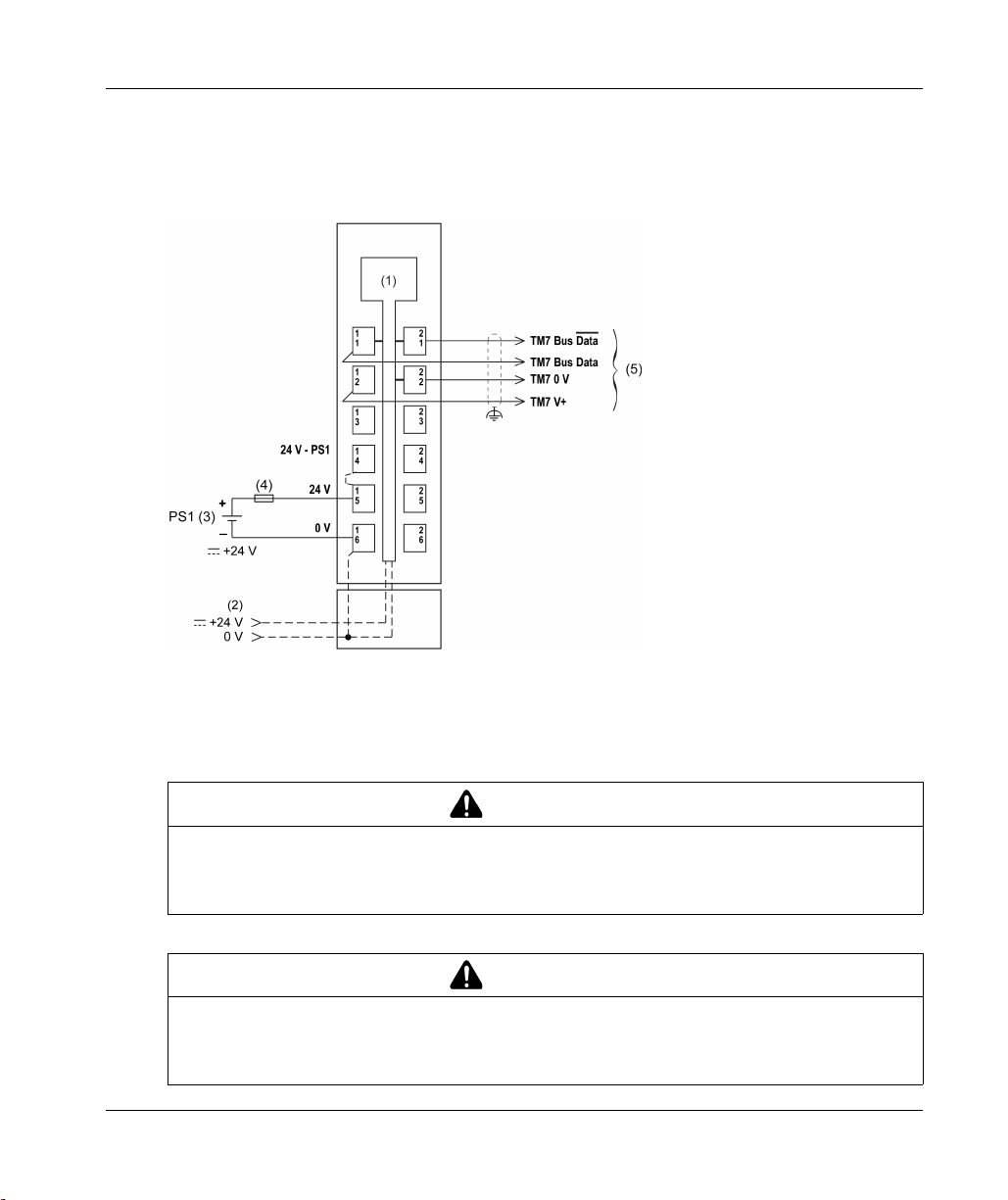
Wiring Diagram
The following figure shows the wiring diagram for the TM5SBET7:
TM5SBET7 Transmitter Electronic Module
(1) Internal electronics
(2) 24 Vdc I/O power segment integrated into the bus bases
(3) PS1/PS2: External isolated power supply 24 Vdc
(4) External fuse, Type T slow-blow: 1 A max., 250 V
(5) TM7 Expansion bus cable (TCSXCN•FNX••E)
WARNING
UNINTENDED EQUIPMENT OPERATION
Properly ground the cable shields as indicated in the related documentation.
Failure to follow these instructions can result in death, serious injury, or equipment damage.
WARNING
UNINTENDED EQUIPMENT OPERATION
Do not connect wires to unused terminals and/or terminals indicated as “No Connection (N.C.)”.
Failure to follow these instructions can result in death, serious injury, or equipment damage.
EIO0000003215 09/2020 47
Page 48

TM5SBET7 Transmitter Electronic Module
48
EIO0000003215 09/2020
Page 49

ModiconTM5
TM5SBER2 Receiver Electronic Module
EIO0000003215 09/2020
TM5SBER2 Receiver Electronic Module
Chapter 5
TM5SBER2 Receiver Electronic Module
What Is in This Chapter?
This chapter contains the following topics:
TM5SBER2 Presentation 50
TM5SBER2 Characteristics 53
TM5SBER2 Wiring Diagram 56
Topic Page
EIO0000003215 09/2020 49
Page 50

TM5SBER2 Receiver Electronic Module
TM5SBER2 Presentation
Main Characteristics
The table below describes the main characteristics of the TM5SBER2 electronic module:
Main Characteristics
Function Receives the TM5 data bus
Maximum bus length 2500 m (8202.1 ft)
Maximum cable distance between
Transmitter and Receiver
Power distribution
Ordering Information
The following figure and table give the references to create a slice with the TM5SBER2 electronic
module:
100 m (328.1 ft)
TM5 power bus
24 Vdc I/O power segment
50
NOTICE
ELECTROSTATIC DISCHARGE
Install a right bus base locking plate to the rightmost slice of all configurations.
Install a left bus base locking plate to the first slice of all remote configurations.
Failure to follow these instructions can result in equipment damage.
EIO0000003215 09/2020
Page 51

TM5SBER2 Receiver Electronic Module
X
l
SBER2
r
e
Number Model Number Description Color
1 TM5ACBM01R
or
TM5ACBM05R
2 TM5SBER2 Electronic module Gray
3 TM5ACTB12PS Terminal block, 12-pins Gray
Bus base
Bus base with address setting
Gray
Gray
Status LEDs
NOTE: For more information, refer to
TM5 bus bases and terminal blocks
The following figure shows the status LEDs for TM5SBER2:
The table below describes the TM5SBER2 status LEDs:
LED Color Status Description
r Green Off No power supply
Single Flash Reset state
Flashing Preoperational state
On Run state
e Red Off OK or no power supply
Double flash Indicates one of the following conditions:
e+r Steady red / single green
flash
TM5 power bus current is too high (overload)
Voltage for the 24 Vdc I/O power segment is too low
Voltage for the TM5 power bus is too low
Invalid firmware
.
EIO0000003215 09/2020 51
Page 52

TM5SBER2 Receiver Electronic Module
LED Color Status Description
X Yellow Off No communication on the TM5 data bus
On TM5 data bus communication in progress
l Red Off TM5 power bus in the acceptable range
On TM5 power bus current is too high (overload)
52
EIO0000003215 09/2020
Page 53

TM5SBER2 Characteristics
Introduction
The TM5SBER2 is a data receiver electronic module. Refer also to the environmental characteristics
(see page 20)
FIRE HAZARD
Use only the correct wire sizes for the maximum current capacity of the I/O channels and power
supplies.
Failure to follow these instructions will result in death or serious injury.
UNINTENDED EQUIPMENT OPERATION
Do not exceed any of the rated values specified in the environmental and electrical characteristics
tables.
Failure to follow these instructions can result in death, serious injury, or equipment damage.
.
TM5SBER2 Receiver Electronic Module
DANGER
WARNING
General Characteristics
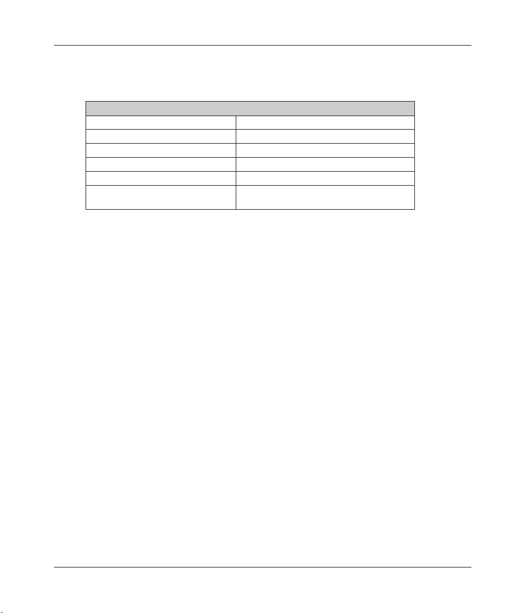
The table below describes the general characteristics of the TM5SBER2 electronic module:
General Characteristics
Rated power supply voltage 24 Vdc
24 Vdc I/O segment current draw 25 mA
Power dissipation 2.22 W max.
Weight 25 g (0.9 oz)
ID code for firmware update 7105 dec
EIO0000003215 09/2020 53
Page 54
TM5SBER2 Receiver Electronic Module
TM5 Power Bus Characteristics
The following table shows the TM5 power bus characteristics of the TM5SBER2 electronic module:
Power supply range 20.4...28.8 Vdc
Rated input current 0.7 A max. at 24 Vdc
Reverse polarity protection Yes
Fuse Integrated, can not be exchanged
Current generated 1156 mA
De-rating - 10...55 °C (14...131 °F): 1156 mA
Parallel operation
Electrical isolation
1 The two power circuits reference the same functional ground (FE) through specific
components designed to reduce effects of electromagnetic interference. These
components are rated at 30 or 60 V.
2 In parallel operation, only 75% of the rated power can be assumed. Please ensure that all
parallel operating power supplies are switched on and off simultaneously.
Do not mount a Power Distribution Module (PDM) side-by-side with a Receiver module.
TM5 power bus characteristics
55...60 °C (131...140 °F): 756 mA
2
Yes
See note
1
54
WARNING
UNINTENDED EQUIPMENT OPERATION
Do not mount a Power Distribution Module (PDM) next to any one of the following modules:
Power Distribution Module (PDM)
Transmitter module TM5SBET1 or TM5SBET7
Receiver module TM5SBER2
Interface Power Distribution Module TM5SPS3 (IPDM)
Analog input module TM5SAI2H or TM5SAI4H
Analog output module TM5SAO4L or TM5SAO4H
Failure to follow these instructions can result in death, serious injury, or equipment damage.
EIO0000003215 09/2020
Page 55
24 Vdc I/O Power Segment Characteristics
The following table shows the 24 Vdc I/O power segment characteristics of the TM5SBER2
electronic module:
24 Vdc I/O power segment characteristics
Power supply range 20.4...28.8 Vdc
Rated power supply voltage 24 Vdc
Maximum current provided 10 A
Reverse polarity protection No
Short circuit protection External fuse type T slow-blow 10 A 250 V
Isolation between power segment and
TM5 power and data buses
1
The isolation of the electronic module is 500 Vac RMS between the electronics powered by the
TM5 bus and those powered by 24 Vdc I/O power segment connected to the module. In practice,
the TM5 electronic module is installed in the bus base, and there is a bridge between the TM5
power bus and the 24 Vdc I/O power segment. The two power circuits reference the same
functional ground (FE) through specific components designed to reduce effects of electromagnetic
interference. These components are rated at 30 Vdc or 60 Vdc. This effectively reduces isolation
of the entire system from the 500 Vac RMS.
See note
TM5SBER2 Receiver Electronic Module
1
EIO0000003215 09/2020 55
Page 56

TM5SBER2 Receiver Electronic Module
TM5SBER2 Wiring Diagram
Wiring Diagram
The following figure shows the wiring diagram for the TM5SBER2:
24 V
1
1
1
2
1
3
1
4
1
5
0 V
1
6
TM5 Bus Data
TM5 Bus Data
(3)
TM5 Bus Ref
(6)
+
PS1 (4)
_
(1) Internal electronics
(2) 24 Vdc I/O power segment integrated into the bus bases
(3) TM5 expansion bus cable (TCSXCNNXNX100)
(4) PS1/PS2: External isolated power supply 24 Vdc
(5) External fuse, Type T slow-blow: 10 A max., 250 V
(6) External fuse, Type T slow-blow: 1 A, 250 V
(1)
2
1
2
2
2
3
24 V - PS224 V - PS1
2
4
(5)
24 V
2
5
0 V
2
6
c +24 Vc +24 V
c +24 V
+
PS2 (4)
_
(2)
0 V
56
WARNING
UNINTENDED EQUIPMENT OPERATION
Properly ground the cable shields as indicated in the related documentation.
Failure to follow these instructions can result in death, serious injury, or equipment damage.
WARNING
UNINTENDED EQUIPMENT OPERATION
Do not connect wires to unused terminals and/or terminals indicated as “No Connection (N.C.)”.
Failure to follow these instructions can result in death, serious injury, or equipment damage.
EIO0000003215 09/2020
Page 57

%
bus base
ModiconTM5
Glossary
EIO0000003215 09/2020
Glossary
!
According to the IEC standard, % is a prefix that identifies internal memory addresses in the logic
controller to store the value of program variables, constants, I/O, and so on.
B
A mounting device that is designed to seat an electronic module on a DIN rail and connect it to the
TM5 bus for M258 and LMC058 logic controllers. Each base bus extends the integrated TM5 data
and electronic power buses as well as the 24 Vdc I/O power segment. The electronic modules are
added to the TM5 system through their insertion on the base bus.
C
CAN
(
controller area network
) A protocol (ISO 11898) for serial bus networks, designed for the interconnection of smart devices (from multiple manufacturers) in smart systems and for real-time industrial
applications. Originally developed for use in automobiles, CAN is now used in a variety of industrial
automation control environments.
CANopen
An open industry-standard communication protocol and device profile specification (EN 50325-4).
configuration
The arrangement and interconnection of hardware components within a system and the hardware
and software parameters that determine the operating characteristics of the system.
control network
A network containing logic controllers, SCADA systems, PCs, HMI, switches, ...
Two kinds of topologies are supported:
flat: all modules and devices in this network belong to same subnet.
2 levels: the network is split into an operation network and an inter-controller network.
These two networks can be physically independent, but are generally linked by a routing device.
controller
Automates industrial processes (also known as programmable logic controller or programmable
controller).
EIO0000003215 09/2020 57
Page 58

Glossary
CSA
(
Canadian standards association
hazardous environments.
D
DIN
(
Deutsches Institut für Normung
standards.
E
electronic module
In a programmable controller system, most electronic modules directly interface to the sensors,
actuators, and external devices of the machine/process. This electronic module is the component
that mounts in a bus base and provides electrical connections between the controller and the field
devices. Electronic modules are offered in a variety of signal levels and capacities. (Some
electronic modules are not I/O interfaces, including power distribution modules and
transmitter/receiver modules.)
element
The short name of the ARRAY element.
EN
EN identifies one of many European standards maintained by CEN (
Standardization
(
European Telecommunications Standards Institute
), CENELEC (
) The Canadian standard for industrial electronic equipment in
) A German institution that sets engineering and dimensional
European Committee for
European Committee for Electrotechnical Standardization
).
), or ETSI
encoder
A device for length or angular measurement (linear or rotary encoders).
equipment
A part of a machine including sub-assemblies such as conveyors, turntables, and so on.
Ethernet
A physical and data link layer technology for LANs, also known as IEEE 802.3.
F
FAST I/O
FAST input/output
while the treatment of these channels are done directly by the controller
firmware
Represents the BIOS, data parameters, and programming instructions that constitute the operating
system on a controller. The firmware is stored in non-volatile memory within the controller.
58
Specific I/O modules with some electrical features (for example, response time)
EIO0000003215 09/2020
Page 59

H
hot swapping
The replacement of a component with a like component while the system remains under power and
operational. The replacement component begins to function automatically after it is installed.
I
I/O
(
input/output
IEC
(
international electrotechnical commission
standards organization that prepares and publishes international standards for electrical,
electronic, and related technologies.
IP 20
(
ingress protection
shown by the letter IP and 2 digits. The first digit indicates 2 factors: helping protect persons and
for equipment. The second digit indicates helping protect against water. IP 20 devices help protect
against electric contact of objects larger than 12.5 mm, but not against water.
IP 67
ingress protection
(
protected against ingress of dust, contact, and water up to an immersion depth of 1 m.
Glossary
)
) A non-profit and non-governmental international
) The protection classification according to IEC 60529 offered by an enclosure,
) The protection classification according to IEC 60529. IP 67 modules are
L
LED
light emitting diode
(
) An indicator that illuminates under a low-level electrical charge.
M
machine
ms
Consists of several
millisecond
(
)
functions
and/or
equipment
.
N
network
A system of interconnected devices that share a common data path and protocol for
communications.
EIO0000003215 09/2020 59
Page 60

Glossary
P
PCI
(
peripheral component interconnect
PDM
power distribution module
(
modules.
T
terminal block
(
terminal block
connections between the controller and the field devices.
U
UL
(
underwriters laboratories
) An industry-standard bus for attaching peripherals.
) A module that distributes either AC or DC field power to a cluster of I/O
) The component that mounts in an electronic module and provides electrical
) A US organization for product testing and safety certification.
60
EIO0000003215 09/2020
Page 61

ModiconTM5
Index
EIO0000003215 09/2020
Index
E
Electronic modules
documentation references,
installation,
environmental characteristics,
23
H
hot swapping,
24
I
installation and Maintenance
installation and Maintenance require-
14
ments,
23
20
T
Technical Data
TM5SBER2,
TM5SBET1,
TM5SBET7,
TM5 receiver
TM5SBER2,
TM5 transmitter
TM5SBET1,
TM5SBET7,
TM5SBER2,
TM5SBET1,
TM5SBET7,
53
41
46
49
37
43
49
37
43
W
wiring rules,
EIO0000003215 09/2020 61
16
Page 62

Index
62
EIO0000003215 09/2020
 Loading...