

Page 1
APPLICATION
For proportional temperature control of pneumatic valves and
actuators to maintain air or liquid temperatures in duct,
plenum chambers, liquid lines, tanks, etc. May also be used
as a low limit thermostat.
SPECIFICATIONS
Thermostat: Proportional two pipe type. Thermostats are
ambient compensated.
Sensing Element: Remote liquid-filled copper.
Control Dial Range: -20 to 240°F (
as -20 to 120°F, reverse side of dial 100 to 240°F.
Throttling Range: Adjustable 3 to 35°F/10
kPa) change in output, factory set at 5°F (3°C).
Output Air Signal: 0.5 psig (3.4 kPa) to supply air pressure
-0.5 (-3.4 kPa).
Action: See Table 1.
Ambient Limits:
Shipping, -40 to 150°F (-40 to 65°C). 0 to 98% R.H.,
non-condensing.
Case Operating, 40 to 150°F (4 to 65°C). 10 to 98%
R.H., non-condensing.
Bulb, 310°F (1
54°C) maximum.
Supply Air Pressure: Clean, oil free, dry air required
(reference EN-123).
Nominal, 20 psig (138 kPa).
Minimum, 15 psig (103 kPa).
Maximum, 30 psig (207 kPa).
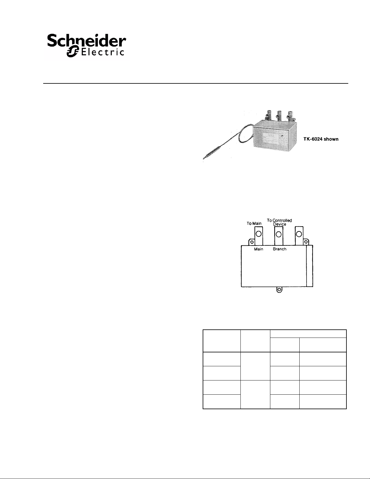
Air Connections: 1/8" FNPT for main, branches and
gauges (not included).
AL-362
Air Consumption for Sizing Air compressor: 0.008 scfm
l/s).
(3.8 m
Air Capacity for Sizing Air Mains: 16 scim (4.4 ml/s).
Mounting: Upright position on a wall or vertical flat surface.
Bulb Dimensions: See Table 1.
Capillary Length: 6’ (1.8 m).
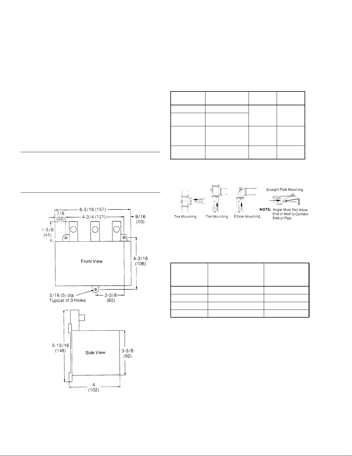
Case Dimensions: 5-13/16" high x 6-3/16" wid e x 4" deep
mm x 157 mm x 102 mm).
(148
ACCESSORIES
AL-362 Stem mounted back connected 0-30 psi gauge
AT-201 3/8" x 9-1/2" with 3/4" MNPT copper bulb well
AT -203 3/8" x 9-1/2" with 3/4" MNPT stainless steel bulb
AT-206 3/8" x 4-1/2" with 1/2" MNPT copper bulb well
AT-208 Duct mounting kit
AT-209 Liquid line or tank mounting kit
AT-211 Bulb shield
AT-539 Pilot pressure kit
TOOL-95 Pneumatic calibration tool kit (required for use
ires AT-209
requ
equires AT-209
well r
as low limit thermostat)
-29 to 115°C). Shipped
psi (2 to 19°C/69
TK-6024, TK-6124, TK-8024,
TK-8124
Pneumatic Bulb Thermostats
General Instructions
MAINTENANCE PARTS
AT-520-011 Relay repair kit
AT-528 Pilot restrictor kit
DYDK-77-031 Thermal element for TK-8X24
DYDK-99-011 Thermal element for TK-6X24
Figure-1 Piping Connections.
Table-1 Specifications.
Bulb
Part Number Action
TK-6024
TK-8024 Averaging
TK-6124
TK-8124 Averaging
a
Direct Acting (DA) - increase output pressure on temperature rise.
Reverse Acting (RA) - Decrease output pressure on temperature rise.
DA
RA
a
a
Style
Straight
Straight
Dimensions
in (mm)
3/8 x 4-5/8
(9.5 x 117)
3/32 x 8’
(2.4 x 2.4 m)
3/8 x 4-5/8
(9.5 x 117)
3/32 x 8’
(2.4 x 2.4 m)
Printed in U.S.A. 12/09 © Copyright 2009 Schneider Electric All Rights Reserved. F-14684-5
Page 2
PRE-INSTALLATION
Inspection
Visually inspect the carton for damage. If damaged, notify the
appropriate carrier immediately. Visually inspect the device for
obvious defects. Return damaged or defective products.
Required Installation Items
• Tools (not provided):
Appropriate drill, drill bits and screwdriver for mounting
screws
Needle nose pliers or 3/16" open-ended wrench to hold
dial shaft
• Appropriate Accessories
• Mounting screws and appropriate fittings (not provided)
INSTALLATION
Caution: Installer must be a qualified, experienced
technician.
Make all connections in accordance with the job piping
diagrams, local and national codes.
Avoid locations near steam or hot water coils or pipes, or
wherever radiant heat will affect the bulb or capillary tube.
THERMOSTAT MOUNTING
Mount the thermostat in an upright position on a wall or vertical
flat surface that does not vibrate.
Three (3) mounting holes 3/16" (5 mm) provided on case.
BULB MOUNTING
Table-2 Liquid Line and Tank for TK-6X24.
Part Number Description Mt. Fitting
a
AT-201
AT-203
AT-206 Copper bulb well 1/2" MNPT
AT-209
a
Requires AT-208.
b
Recommended installation is with a bulb well.
Copper bulb well
Stainless steel bulb
a
b
well
Bulb mounting kit 3/4" MNPT
3/4" MNPT
Insertion
Size
1/2" dia.
OD (9-1/2”
long
1/2" dia.
OD 4-1/2"
long
Length of
bulb
Figure-2 Mounting Dimensions.
Figure-3 Bulb Well Installation.
Table-3 Application Limitations at 250°F Fluid Temp.
(Max. 350°F)
Part Number
AT-201 11 250
AT-203 20 500
AT-206 11 250
AT-209 4 150
Max. Recommended
Velocity (FPS)
Max.
Recommended
Static Pressure
(psig)
Installation of TK-6X24 Bulb into AT-206 Bulb Well
1. Install AT-206 bulb well into 1/2" FNPT opening.
2. Place packing (included with AT-206) over bulb support section and insert bulb into well.
3. Push packing into nut on well using a screwdriver.
2 © Copyright 2009 Schneider Electric All Rights Reserved. F-14684-5
Page 3

Figure-4 Installation of TK-6X24 into AT-206 Bulb Well.
Installation of TK-6X24 Bulb into AT - 201 or AT-203 Bulb Well (Requires AT-209 Kit)
1. Install bulb well or adaptor from AT-209 into 3/4" FNPT opening.
2. Place packing nut, washers and packing from AT-209 over bulb support section and insert bulb into well or AT-209 adaptor.
3. Push interlocking washers and packing into well or adaptor and tighten packing nut until firmly sealed.
Outdoor Installation of TK-6X24
Install with AT-211 kit as shown below.
1. Mount bulb to outside wall or surface with bulb clip.
2. Place shield over bulb and fasten to mounting surface.
Figure-7 Installation of TK-6X24 Using AT-211 Outside Bulb
Shield.
Duct Installation of TK-6X24
Install bulb with AT-208 kit as shown below.
Figure-5 Installation of TK-6X24 Bulb into AT-201 or AT-203
Bulb Well with Required AT-209 Kit.
Duct Installation of TK-8X24
Install averaging bulb mounting with two AT -208 kits as shown
below.
Figure-6 Installation of TK-8X24 Using AT-208 Duct
Mounting Kit.
Note: Access panel may be required to allow for tying bulb to
copper after it is installed in the duct.
Figure-8 Installation of TK-6X24 Using AT-208 Duct
Mounting Kit.
ADJUSTMENTS
Thermostats are shipped from the factory calibrated to provide
an 8 psig control line pressure when the control point is equal
to the setpoint.
To make all adjustments, remove the cover by first loosening
the cover screws. Squeeze slightly on the top and bottom and
pull forward and down, unhooking the top first.
Setpoint Dial
The thermostat has a total dial range of -20° to +240°F. One
side of the dial is marked -20 to 120 and the other 100 to 240.
If a setpoint higher than 120° is required, proceed as follows:
1. Rotate setpoint dial to 110°.
2. using a 3/16" open end wrench, hold hex shaft below setpoint dial.
3. Loosen screw that holds dial in place and remove.
4. Remove dial and turn over to the 100 to 240 side.
5. Start screw into dial post, before tightening line up dial at 110°, and tighten. Be sure to hold dial post with wrench when tightening screw tight.
6. Proceed with standard throttling range and calibration procedures.
F-14684-5 © Copyright 2009 Schneider Electric All Rights Reserved. 3
Page 4

Throttling Range
The throttling range should be set at the lowes t va lue
which will allow the thermostat to control the system
without cycling under normal load condi tions. The most
satisfactory setting will vary with he type of control system.
The throttling range is changed by sliding the throttling range
adjustment slider to its proper position. See Figure 9.
Calibration of the thermostat should be checked after the
throttling range has been changed. When making the
throttling range adjustment, care should be taken to prevent
excessive side forces on the feedback lever. In no case should
the pivot point be raised when the adjustment is made.
Throttling Range Adjustment
If the throttling range of the thermostat as shipped is not
satisfactory, proceed as follows:
1. Move slider to approximate position desired (see Figure 9).
2. With instrument measuring a stable temperature, rotate setpoint dial CCW to low end of scale, then CW to that temperature “setpoint”.
3. Adjust setpoint calibration screw until 3 psig (RA) or 13 psig (DA) is read on branch gauge.
4. Rotate setpoint dial CW toward upper end of scale until 13 psig (RA) or 3 psig (DA) is read on branch gauge.
5. Difference between setpoint dial readings in step 2 and 4 is the approximate mechanical throttling range of the thermostat. The thermal throttling range will be equal to or less than the mechanical throttling range.
6. If the throttling range in step 5 does not provide the
control desired, move throttling range slider in
appropriate direction and repeat steps 2 through 5 until
desired control is obtained. If unable to obtain satisfactory
control, check system for proper sizing of components
being controlled and sensing element location.
Figure-9 Thermostat Adjustments.
4 © Copyright 2009 Schneider Electric All Rights Reserved. F-14684-5
Page 5

CALIBRATION
After the installation has been completed, the thermostat
should be checked for calibration. As a nominal calibration,
the controlled branch pressure should be 8 psig when the
setpoint is equal to the bulb temperature, indicated by a
thermometer located near the bulb. In some applications, a
value other than 8 psig will be required to get the desired
control results. Change the 8 psig will be required to get the
desired control results. Change the 8 psig designation as used
in the calibration procedure, should this be the case.
1. Using the branch gauges, or a separate test gauge
connected to the branch test port (see Note), rotate the dial
[direct acting (DA) - lower , reverse acting (RA) - rai se] in
the appropriate direction. The branch pressure should
raise to be the same as the supply pressure ±1 psi.
Note: As shown in Figure 9, each thermostat is furnished
with a branch test connection. If a test gauge is to be used at
this connection, use a 5/64" Alle n w r en ch to un scre w
(counterclockwise) the test point screw one full turn before
attaching test gauge.
2. Measure the temperature at the bulb. This must be a stable temperature.
3. Rotate the dial to this temperature.
4. Turn the setpoint calibration screw (see Figure 9) until a branch pressure of 8 psig ±1 psi is read on the branch gauge.
1. Remove restriction cover plate, restriction and two gaskets (see Figure 9 for location).
2. Using the parts from the AT-539 place in order one gasket, restrictor plate, the other gasket and cover plate with the tubing attached on the restrictor mounting pad. Then install the two (2) screws.
3. Route 5/32" plastic tubing through hole in base and connect to constant 15 or 20 psig main.
Calibration When Used As Low Limit
1. Determine throttling range required. This normally is approximately 10°F.
2. Adjust branch pressure from first thermostat to maximum branch pressure.
3. Adjust throttling range as described in Throttling Range Adjustment on page 3.
4. After throttling range is adjusted, proceed with calibration of control point as described in Calibration.
FIELD SERVICE
Relay repair kit, pilot restrictor and thermal elements are
available. See Maintenance Parts on page 1 for specific
part numbers.
Note: The hex nut on the adjusting screw is used to provide
tension only and should not be loosened when making
adjustments.
5. Turn the dial to the desired setpoint.
6. If separate test gauge is used, remove gauge, tighten test point screw and replace cover.
7. Observe operation of system for satisfactory control. If necessary, recalibrate after system has come in control and stabilized.
USE AS A LOW LIMIT THERMOSTAT
These thermostats may be used as low limit thermostats.
Normally in this application, they are used in series with the
branch pressure of another proportional thermostat. When
using two proportional thermostats in series, the second unit
must have an external main air source for the pilot chamber of
the thermostat. This is required to insure the operation of the
second thermostat at low branch pressure from the first
thermostat. An external pilot pressure kit is required for this.
The part number of this kit is AT-539.
Attachment of AT-539
To attach the AT -539 external pilot pressure kit, u se the
following procedure.
MAINTENANCE
Regular maintenance of the total system is
recommended to assure sustained optimum
performance.
F-14684-5 © Copyright 2009 Schneider Electric All Rights Reserved. 5
Page 6

On Oc tober 1st, 2009, TA C became the Buildings business of its pa rent company Schneider Electri c. This document reflect s the visual identit y of Schneider Electric,
ho wever t her e rema ins referenc es to TAC as a corpora te brand in the body copy. As each document is updated, the body copy will be changed to reflect appropriate
corporate brand changes.
Copyright 2009, Schneider Electric
All brand names, trademarks and registered
trademarks are the property of their respective
owners. Information contained within this
document is subject to change without notice.
F-14684-5
 Loading...