

Page 1

Advantys STB
Standard Ethernet Modbus
TCP/IP Network Interface Module
Applications Guide
890USE17700 Version 2.0
31003688 01
31003688 01
Page 2

2
890USE17700 April 2004
Page 3
Table of Contents
Safety Information . . . . . . . . . . . . . . . . . . . . . . . . . . . . . . . . . . . . 7
About the Book . . . . . . . . . . . . . . . . . . . . . . . . . . . . . . . . . . . . . . . 9
Chapter 1 Introduction. . . . . . . . . . . . . . . . . . . . . . . . . . . . . . . . . . . . . . . . . 11
At a Glance . . . . . . . . . . . . . . . . . . . . . . . . . . . . . . . . . . . . . . . . . . . . . . . . . . . . . 11
What Is a Network Interface Module? . . . . . . . . . . . . . . . . . . . . . . . . . . . . . . . . . 12
What Is Advantys STB? . . . . . . . . . . . . . . . . . . . . . . . . . . . . . . . . . . . . . . . . . . . 15
STB NIP 2212 Product Overview . . . . . . . . . . . . . . . . . . . . . . . . . . . . . . . . . . . . 19
Ethernet Communications and Connectivity . . . . . . . . . . . . . . . . . . . . . . . . . . . . 21
Chapter 2 The STB NIP 2212 NIM . . . . . . . . . . . . . . . . . . . . . . . . . . . . . . . . 23
At a Glance . . . . . . . . . . . . . . . . . . . . . . . . . . . . . . . . . . . . . . . . . . . . . . . . . . . . . 23
External Features of the STB NIP 2212 . . . . . . . . . . . . . . . . . . . . . . . . . . . . . . . 24
STB NIP 2212 Network Interface . . . . . . . . . . . . . . . . . . . . . . . . . . . . . . . . . . . . 26
Rotary Switches . . . . . . . . . . . . . . . . . . . . . . . . . . . . . . . . . . . . . . . . . . . . . . . . . 28
LED Indicators. . . . . . . . . . . . . . . . . . . . . . . . . . . . . . . . . . . . . . . . . . . . . . . . . . . 30
The CFG Interface. . . . . . . . . . . . . . . . . . . . . . . . . . . . . . . . . . . . . . . . . . . . . . . . 33
The Power Supply Interface . . . . . . . . . . . . . . . . . . . . . . . . . . . . . . . . . . . . . . . . 35
Logic Power. . . . . . . . . . . . . . . . . . . . . . . . . . . . . . . . . . . . . . . . . . . . . . . . . . . . . 37
Selecting a Source Power Supply for the Island’s Logic Power Bus. . . . . . . . . . 39
Module Specifications . . . . . . . . . . . . . . . . . . . . . . . . . . . . . . . . . . . . . . . . . . . . . 42
Chapter 3 Configuring the Island Bus . . . . . . . . . . . . . . . . . . . . . . . . . . . . 45
At a Glance . . . . . . . . . . . . . . . . . . . . . . . . . . . . . . . . . . . . . . . . . . . . . . . . . . . . . 45
Auto-Addressing . . . . . . . . . . . . . . . . . . . . . . . . . . . . . . . . . . . . . . . . . . . . . . . . . 46
Auto-Configuration . . . . . . . . . . . . . . . . . . . . . . . . . . . . . . . . . . . . . . . . . . . . . . . 49
Installing the STB XMP 4440 Optional Removable Memory Card . . . . . . . . . . . 50
Using the STB XMP 4440 Optional Removable Memory Card to Configure the
Island Bus . . . . . . . . . . . . . . . . . . . . . . . . . . . . . . . . . . . . . . . . . . . . . . . . . . . . . . 53
The RST Button. . . . . . . . . . . . . . . . . . . . . . . . . . . . . . . . . . . . . . . . . . . . . . . . . . 55
RST Functionality . . . . . . . . . . . . . . . . . . . . . . . . . . . . . . . . . . . . . . . . . . . . . . . . 56
890USE17700 April 2004 3
Page 4

Chapter 4 IP Parameters . . . . . . . . . . . . . . . . . . . . . . . . . . . . . . . . . . . . . . . 59
At a Glance . . . . . . . . . . . . . . . . . . . . . . . . . . . . . . . . . . . . . . . . . . . . . . . . . . . . . 59
How the STB NIP 2212 Obtains IP Parameters . . . . . . . . . . . . . . . . . . . . . . . . . 60
The IP Address Assignment Process . . . . . . . . . . . . . . . . . . . . . . . . . . . . . . . . . 63
Chapter 5 STB NIP 2212 Web Server . . . . . . . . . . . . . . . . . . . . . . . . . . . . . 65
At a Glance . . . . . . . . . . . . . . . . . . . . . . . . . . . . . . . . . . . . . . . . . . . . . . . . . . . . . 65
5.1 Introduction to the Embedded Web Server . . . . . . . . . . . . . . . . . . . . . . . . . . . . . 66
At a Glance . . . . . . . . . . . . . . . . . . . . . . . . . . . . . . . . . . . . . . . . . . . . . . . . . . . . . 66
About the Embedded Web Server . . . . . . . . . . . . . . . . . . . . . . . . . . . . . . . . . . . . 67
Properties Web Page. . . . . . . . . . . . . . . . . . . . . . . . . . . . . . . . . . . . . . . . . . . . . . 69
5.2 Web Server Configuration Options . . . . . . . . . . . . . . . . . . . . . . . . . . . . . . . . . . . 70
At a Glance . . . . . . . . . . . . . . . . . . . . . . . . . . . . . . . . . . . . . . . . . . . . . . . . . . . . . 70
Configuration Web Page . . . . . . . . . . . . . . . . . . . . . . . . . . . . . . . . . . . . . . . . . . . 71
Configuring an IP Address for the STB NIP 2212 . . . . . . . . . . . . . . . . . . . . . . . . 72
Configuring Master Controllers . . . . . . . . . . . . . . . . . . . . . . . . . . . . . . . . . . . . . . 77
Master Configurator Web Page . . . . . . . . . . . . . . . . . . . . . . . . . . . . . . . . . . . . . . 79
Configuring a Role Name. . . . . . . . . . . . . . . . . . . . . . . . . . . . . . . . . . . . . . . . . . . 82
5.3 Web Server Security . . . . . . . . . . . . . . . . . . . . . . . . . . . . . . . . . . . . . . . . . . . . . . 85
At a Glance . . . . . . . . . . . . . . . . . . . . . . . . . . . . . . . . . . . . . . . . . . . . . . . . . . . . . 85
Web Access Password Protection. . . . . . . . . . . . . . . . . . . . . . . . . . . . . . . . . . . . 86
Configuration Password Protection . . . . . . . . . . . . . . . . . . . . . . . . . . . . . . . . . . . 89
5.4 Web Server Diagnostic Options. . . . . . . . . . . . . . . . . . . . . . . . . . . . . . . . . . . . . . 91
At a Glance . . . . . . . . . . . . . . . . . . . . . . . . . . . . . . . . . . . . . . . . . . . . . . . . . . . . . 91
Diagnostics Web Page. . . . . . . . . . . . . . . . . . . . . . . . . . . . . . . . . . . . . . . . . . . . . 92
Ethernet Statistics . . . . . . . . . . . . . . . . . . . . . . . . . . . . . . . . . . . . . . . . . . . . . . . . 93
STB NIP 2212 Registers Web Page . . . . . . . . . . . . . . . . . . . . . . . . . . . . . . . . . . 94
I/O Data Values Web Page . . . . . . . . . . . . . . . . . . . . . . . . . . . . . . . . . . . . . . . . . 96
Island Configuration Web Page . . . . . . . . . . . . . . . . . . . . . . . . . . . . . . . . . . . . . . 98
Island Parameters Web Page . . . . . . . . . . . . . . . . . . . . . . . . . . . . . . . . . . . . . . . 99
Error Log Web Page . . . . . . . . . . . . . . . . . . . . . . . . . . . . . . . . . . . . . . . . . . . . . 100
5.5 SNMP Services . . . . . . . . . . . . . . . . . . . . . . . . . . . . . . . . . . . . . . . . . . . . . . . . . 102
At a Glance . . . . . . . . . . . . . . . . . . . . . . . . . . . . . . . . . . . . . . . . . . . . . . . . . . . . 102
SNMP Device Management. . . . . . . . . . . . . . . . . . . . . . . . . . . . . . . . . . . . . . . . 103
Configure SNMP Web Page . . . . . . . . . . . . . . . . . . . . . . . . . . . . . . . . . . . . . . . 105
About the Schneider Private MIBs. . . . . . . . . . . . . . . . . . . . . . . . . . . . . . . . . . . 107
Transparent Factory Ethernet (TFE) MIB Subtree. . . . . . . . . . . . . . . . . . . . . . . 109
Port502 Messaging Subtree . . . . . . . . . . . . . . . . . . . . . . . . . . . . . . . . . . . . . . . 110
Web MIB Subtree. . . . . . . . . . . . . . . . . . . . . . . . . . . . . . . . . . . . . . . . . . . . . . . . 111
Equipment Profiles Subtree . . . . . . . . . . . . . . . . . . . . . . . . . . . . . . . . . . . . . . . . 112
4 890USE17700 April 2004
Page 5

Chapter 6 Data Exchange . . . . . . . . . . . . . . . . . . . . . . . . . . . . . . . . . . . . . 115
At a Glance . . . . . . . . . . . . . . . . . . . . . . . . . . . . . . . . . . . . . . . . . . . . . . . . . . . . 115
Data Exchange with the STB NIP 2212 . . . . . . . . . . . . . . . . . . . . . . . . . . . . . . 116
Reading Diagnostic Data. . . . . . . . . . . . . . . . . . . . . . . . . . . . . . . . . . . . . . . . . . 125
Modbus Commands Supported by the STB NIP 2212 . . . . . . . . . . . . . . . . . . . 134
Modbus Error Codes. . . . . . . . . . . . . . . . . . . . . . . . . . . . . . . . . . . . . . . . . . . . . 137
Chapter 7 Connection Example . . . . . . . . . . . . . . . . . . . . . . . . . . . . . . . . 139
At a Glance . . . . . . . . . . . . . . . . . . . . . . . . . . . . . . . . . . . . . . . . . . . . . . . . . . . . 139
Introduction . . . . . . . . . . . . . . . . . . . . . . . . . . . . . . . . . . . . . . . . . . . . . . . . . . . . 140
Network Architecture. . . . . . . . . . . . . . . . . . . . . . . . . . . . . . . . . . . . . . . . . . . . . 141
Sample Configuration . . . . . . . . . . . . . . . . . . . . . . . . . . . . . . . . . . . . . . . . . . . . 142
Modbus Functions Supported by the STB NIP 2212. . . . . . . . . . . . . . . . . . . . . 146
Chapter 8 Advanced Configuration Features . . . . . . . . . . . . . . . . . . . . . 149
At a Glance . . . . . . . . . . . . . . . . . . . . . . . . . . . . . . . . . . . . . . . . . . . . . . . . . . . . 149
STB NIP 2212 Configurable Parameters . . . . . . . . . . . . . . . . . . . . . . . . . . . . . 150
Configuring Mandatory Modules . . . . . . . . . . . . . . . . . . . . . . . . . . . . . . . . . . . . 153
Prioritizing a Module . . . . . . . . . . . . . . . . . . . . . . . . . . . . . . . . . . . . . . . . . . . . . 155
What Is a Reflex Action?. . . . . . . . . . . . . . . . . . . . . . . . . . . . . . . . . . . . . . . . . . 156
Island Fallback Scenarios . . . . . . . . . . . . . . . . . . . . . . . . . . . . . . . . . . . . . . . . . 161
Saving Configuration Data . . . . . . . . . . . . . . . . . . . . . . . . . . . . . . . . . . . . . . . . 163
Protecting Configuration Data . . . . . . . . . . . . . . . . . . . . . . . . . . . . . . . . . . . . . . 164
A Modbus View of the Island’s Data Image. . . . . . . . . . . . . . . . . . . . . . . . . . . . 165
The Island’s Process Image Blocks . . . . . . . . . . . . . . . . . . . . . . . . . . . . . . . . . 168
The HMI Blocks in the Island Data Image. . . . . . . . . . . . . . . . . . . . . . . . . . . . . 170
Glossary . . . . . . . . . . . . . . . . . . . . . . . . . . . . . . . . . . . . . . . . . . . . . 173
Index . . . . . . . . . . . . . . . . . . . . . . . . . . . . . . . . . . . . . . . . . . . . . 189
890USE17700 April 2004 5
Page 6

6 890USE17700 April 2004
Page 7
Safety Information
§
Important Information
NOTICE Read these instructions carefully, and look at the equipment to become familiar with
the device before trying to install, operate, or maintain it. The following special
messages may appear throughout this documentation or on the equipment to warn
of potential hazards or to call attention to information that clarifies or simplifies a
procedure.
The addition of this symbol to a Danger or Warning safety label indicates
that an electrical hazard exists, which will result in personal injury if the
instructions are not followed.
This is the safety alert symbol. It is used to alert you to potential personal
injury hazards. Obey all safety messages that follow this symbol to avoid
possible injury or death.
DANGER
DANGER indicates an imminently hazardous situation, which, if not avoided,
will result in death, serious injury, or equipment damage.
WARNING
WARNING indicates a potentially hazardous situation, which, if not avoided, can
result in death, serious injury, or equipment damage.
CAUTION
CAUTION indicates a potentially hazardous situation, which, if not avoided, can
result in injury or equipment damage.
890USE17700 April 2004 7
Page 8

Safety Information
PLEASE NOTE Electrical equipment should be serviced only by qualified personnel. No responsi-
bility is assumed by Schneider Electric for any consequences arising out of the use
of this material. This document is not intended as an instruction manual for untrained
persons.
© 2004 Schneider Electric. All Rights Reserved.
8
890USE17700 April 2004
Page 9

About the Book
At a Glance
Document Scope This Guide describes the hardware and software features of the Advantys
STB NIP 2212, which enables an island of Advantys STB modules to function as a
node on an Ethernet LAN.
The Ethernet LAN on which an island resides uses Transport Control Protocol/
Internet Protocol as its transport layer. The Modbus protocol runs over the TCP/IP
layer. This way, an Ethernet host device can control an island with Modbus
commands. The Modbus protocol allows devices that can connect only to the RS232 port on other Advantys STB NIMs to connect to the STB NIP 2212’s fieldbus
port, too.
The following information appears in this guide:
z
the role of the standard NIM as the gateway between Ethernet TCP/IP and the
Advantys STB island
z
the NIM’s integrated power supply and its role in the distribution of logic power
across the island bus
z
common external interfaces:
z
the two-pin connector to an external SELV-rated power supply
z
RS-232 interface to optional devices, including the Advantys configuration
software and an HMI panel
z
the optional removable memory card
z
advanced configuration features, such as island fallback scenarios
z
STB NIP 2212 specific features, including its global connectivity capabilities
z
how to configure an STB NIP 2212 with IP parameters
z
how to connect the STB NIP 2212 to an Ethernet network
z
STB NIP 2212 web-based configuration and troubleshooting features
z
SNMP management services
Who Should Use This Manual?
This manual is intended to support the customer who has installed the
Advantys STB island bus on an Ethernet LAN and needs to understand the
STB NIP 2212’s local and remote communications capabilities.
This manual assumes familiarity with the Modbus protocol.
890USE17700 April 2004 9
Page 10

About the Book
Validity Note The data and illustrations found in this book are not binding. We reserve the right to
modify our products in line with our policy of continuous product development. The
information in this document is subject to change without notice and should not be
construed as a commitment by Schneider Electric.
Related
Documents
Title of Documentation Reference Number
Advantys STB System Planning and Installation Guide 890USE17100
Advantys STB Hardware Components Reference Guide 890USE17200
Advantys STB Configuration Software Quick Start Guide 890USE18000
Advantys STB Reflex Actions Reference Guide 890USE18300
Transparent Factory Network Design and Cabling Guide 490USE13400
Product Related
Warnings
Schneider Electric assumes no responsibility for any errors that may appear in this
document. If you have any suggestions for improvements or amendments or have
found errors in this publication, please notify us.
No part of this document may be reproduced in any form or by any means, electronic
or mechanical, including photocopying, without express written permission of
Schneider Electric. All rights reserved. Copyright 2004.
All pertinent state, regional, and local safety regulations must be observed when
installing and using this product. For reasons of safety and to assure compliance
with documented system data, only the manufacturer should perform repairs to
components.
When controllers are used for applications with technical safety requirements,
please follow the relevant instructions.
Failure to use Schneider Electric software or approved software with our hardware
products may result in injury, harm, or improper operating results.
Failure to observe this product related warning can result in injury or equipment
damage.
User Comments We welcome your comments about this document. You can reach us by e-mail at
TECHCOMM@modicon.com
10
890USE17700 April 2004
Page 11

Introduction
1
At a Glance
Introduction This chapter provides a general overview of the Advantys STB standard network
interface module and the Advantys STB island bus. The chapter concludes with an
introduction to the specific features of the STB NIP 2212 NIM.
What's in this
Chapter?
This chapter contains the following topics:
Topic Page
What Is a Network Interface Module? 12
What Is Advantys STB? 15
STB NIP 2212 Product Overview 19
Ethernet Communications and Connectivity 21
890USE17700 April 2004 11
Page 12

Introduction
What Is a Network Interface Module?
Purpose Every island requires a network interface module (NIM) in the leftmost location of the
primary segment. Physically, the NIM is the first (leftmost) module on the island bus.
Functionally, it is the gateway to the island bus—all communications to and from the
island bus pass through the NIM. The NIM also has an integrated power supply that
provides logic power to the island modules.
The Fieldbus
Network
Communications
Roles
An island bus is a node of distributed I/O on an open fieldbus network, and the NIM
is the island’s interface to that network. The NIM supports data transfers over the
fieldbus network between the island and the fieldbus master.
The physical design of the NIM makes it compatible with both an Advantys STB
island and your specific fieldbus master. Whereas the fieldbus connector on each
NIM type may differ, the location on the module front panel is essentially the same.
Other NIM connectors, such as the power supply interface and the CFG interface
(See The CFG Interface, p. 33), are identical for all NIM types.
Communications capabilities provided on a standard NM include:
Function Role
data exchange The NIM manages the exchange of input and output data
between the island and the fieldbus master. Input data, stored in
native island bus format, is converted to a fieldbus-specific
format that can be read by the fieldbus master. Output data
written to the NIM by the master is sent across the island bus to
update the output modules and is automatically reformatted.
configuration services Custom services can be performed by the Advantys
configuration software. These services include changing the
operating parameters of the I/O modules, fine-tuning island bus
performance, and configuring reflex actions. The Advantys
configuration software runs on a computer attached to the NIM’s
CFG port.
human-machine interface
(HMI) operations
An HMI panel can be configured as an input and/or output
device on the island bus. As an input device, it can write data
that can be received by the fieldbus master; as an output device,
it can receive updated data from the fieldbus master. The HMI
can also monitor island status, data, and diagnostic information.
The HMI panel must be attached to the NIM’s CFG port.
12
890USE17700 April 2004
Page 13

Introduction
Integrated Power
Supply
The NIM’s built-in 24-to-5 VDC power supply provides logic power to the I/O
modules on the primary segment of the island bus. The power supply requires a
24 VDC external power source. It converts the 24 VDC to 5 V of logic power,
providing 1.2 A of current to the island. Individual STB I/O modules in an island
segment generally draw a current load of between 50 and 90 mA. (Consult the
Advantys STB Hardware Components Reference Guide [890 USE 172] for a
particular module’s specifications.) If the current drawn by the I/O modules totals
more than 1.2 A, additional STB power supplies need to be installed to support the
load.
The NIM delivers the logic power signal to the primary segment only. Special
STB XBE 1200 beginning-of-segment (BOS) modules, located in the first slot of
each extension segment, have their own built-in power supplies, which will provide
logic power to the STB I/O modules in the extension segments. Each BOS module
that you install requires 24 VDC from an external power supply.
890USE17700 April 2004 13
Page 14
Introduction
Structural
Overview
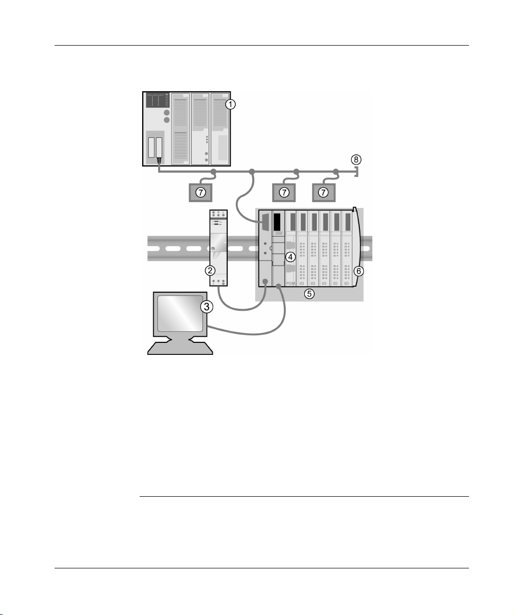
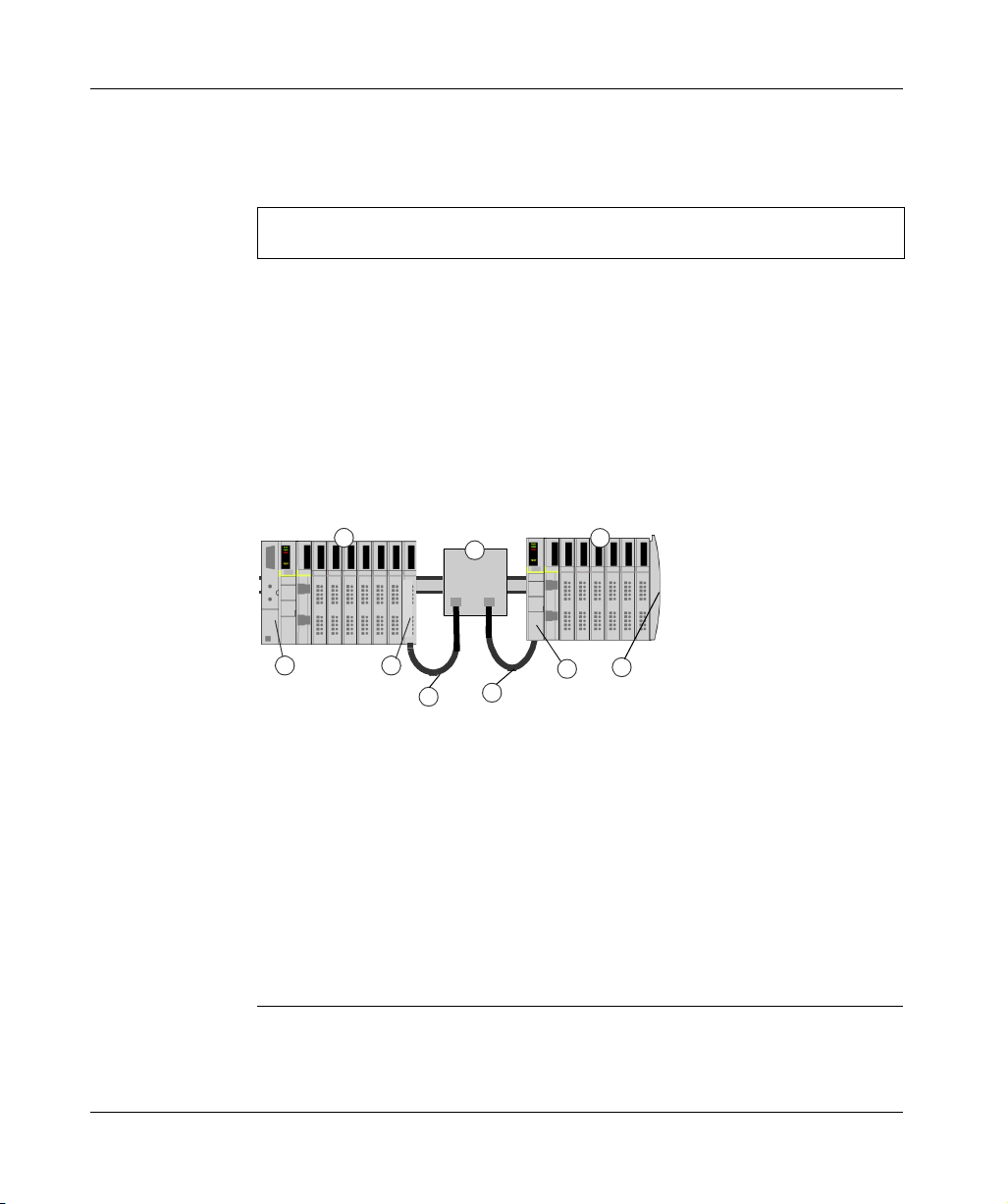
The following figure illustrates the multiple roles of the NIM. The figure provides a
network view and a physical representation of the island bus:
14
1 fieldbus master
2 external 24 VDC power supply, the source for logic power on the island
3 external device connecting to the CFG port—a computer running the Advantys
configuration software or an HMI panel
4 power distribution module (PDM)
5 island node
6 island bus terminator plate
7 other nodes on the fieldbus network
8 fieldbus network terminator (if required)
890USE17700 April 2004
Page 15

Introduction
What Is Advantys STB?
Introduction Advantys STB is an assembly of distributed I/O, power, and other modules that
function together as an island node on an open fieldbus network. Advantys STB
delivers a highly modular and versatile slice I/O solution for the manufacturing
industry, with a migration path to the process industry.
Advantys STB lets you design an island of distributed I/O where the I/O modules can
be installed as close as possible to the mechanical field devices that they control.
This integrated concept is known as mechatronics.
Island Bus I/O An Advantys STB island can support as many as 32 I/O modules. These modules
may be Advantys STB I/O modules, preferred modules, and standard CANopen
devices.
The Primary
Segment
STB I/O modules on an island may be interconnected in groups called segments.
Every island has at least one segment, called the primary segment—it is always the
first segment on the island bus. The NIM is the first module in the primary segment.
The primary segment must contain at least one Advantys STB I/O module and can
support an I/O load of up to 1.2 A. The segment also contains one or more power
distribution modules (PDMs), which distribute field power to the I/O modules.
890USE17700 April 2004 15
Page 16
Introduction
Extension
Segments
When you are using a standard NIM, Advantys STB I/O modules that do not reside
in the primary segment can be installed in extension segments. Extension segments
are optional segments that enable an island to be a truly distributed I/O system. The
island bus can support as many as six extension segments.
Special extension modules and extension cables are used to connect segments in
a series. The extension modules are:
z
the STB XBE 1000 EOS module, which is the last module in a segment if the
island bus is extended
z
the STB XBE 1200 BOS module, which is the first module in an extension
segment
The BOS module has a built-in 24-to-5 VDC power supply similar to the NIM. The
BOS power supply also provides 1.2 A of logic power to the STB I/O modules in an
extension segment.
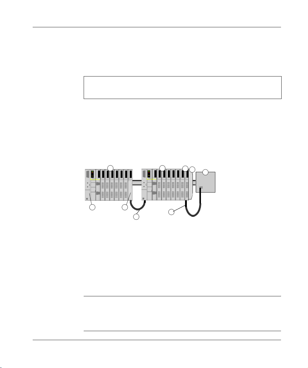
Extension modules are connected by lengths of STB XCA 100x cable that extend
the island communication bus from the previous segment to the next BOS module:
1
2 3
4
5
6
7
8
9
16
10 11
1 primary segment
2 NIM
3 STB XBE 1000 EOS bus extension module
4 1 m length STB XCA 1002 bus extension cable
5 first extension segment
6 STB XBE 1200 BOS bus extension module for the first extension segment
7 another STB XBE 1000 EOS extension module
8 4.5 m length STB XCA 1003 bus extension cable
9 second extension segment
10 STB XBE 1200 BOS bus extension module for the second extension segment
11 STB XMP 1100 termination plate
Bus extension cables are available in various lengths, ranging from 0.3 m (1 ft) to
14.0m (45.9ft).
890USE17700 April 2004
Page 17
Introduction
Preferred
Modules
An island bus can also support those auto-addressable modules referred to as
preferred modules. Preferred modules do not mount in segments, but they do count
as part of the 32-module maximum system limit.
Note: If you want to include preferred modules in your island, you need to configure
the island using the Advantys configuration software.
A preferred module can connect to an island bus segment via an STB XBE 1000
EOS module and a length of STB XCA 100x bus extension cable. Each preferred
module has two IEEE 1394-style cable connectors, one to receive the island bus
signals and the other to transmit them to the next module in the series. Preferred
modules are also equipped with termination, which must be enabled if a preferred
module is the last device on the island bus and must be disabled if other modules
follow the preferred device on the island bus.
Preferred modules can be chained to one another in a series, or they can connect
to Advantys STB segments. As shown in the following figure, a preferred module
passes the island bus communications signal from the primary segment to an
extension segment of Advantys STB I/O modules:
1
2 3
5
4
6
7
9
8
1 primary segment
2 NIM
3 STB XBE 1000 EOS bus extension module
4 1 m length STB XCA 1002 bus extension cable
5 preferred module
6 1 m length STB XCA 1002 bus extension cable
7 extension segment of Advantys STB I/O modules
8 STB XBE 1200 BOS bus extension module for the extension segment
9 STB XMP 1100 termination plate
890USE17700 April 2004 17
Page 18
Introduction
Standard
CANopen
Devices
You may also install one or more standard CANopen devices on an island. These
devices are not auto-addressable, and they must be installed at the end of the island
bus. If you want to install standard CANopen devices on an island, you need to use
an STB XBE 2100 CANopen extension module as the last module in the last
segment.
Note: If you want to include standard CANopen devices in your island, you need
to configure the island using the Advantys configuration software, and you need to
configure the island to operate at 500 kbaud.
Because standard CANopen devices cannot be auto-addressed on the island bus,
they must be addressed using physical addressing mechanisms on the devices. The
standard CANopen devices together with the CANopen extension module form a
sub -network on the island bus that needs to be separately terminated at the
beginning and end. A terminator resistor is included in the STB XBE 2100 CANopen
extension module for one end of the extension sub-network; the last device on the
CANopen extension must also be terminated with 120 Ω. The rest of the island bus
needs to be terminated after the CANopen extension module with an
STB XMP 1100 termination plate:
1
2 3
4
1 primary segment
2 NIM
3 STB XBE 1000 EOS bus extension module
4 1 m length STB XCA 1002 bus extension cable
5 extension segment
6 STB XBE 2100 CANopen extension module
7 STB XMP 1100 termination plate
8 typical CANopen cable
7 standard CANopen device with 120 Ω termination
5
6
7
9
8
Length of the
Island Bus
18
The maximum length of an island bus—the maximum distance between the NIM and
the last device on the island—is 15 m (49.2 ft). This length must take into account
the extension cables between segments, extension cables between preferred
modules, and the space consumed by the devices themselves.
890USE17700 April 2004
Page 19

Introduction
STB NIP 2212 Product Overview
Introduction An Advantys STB island bus configured with an STB NIP 2212 standard NIM can
function transparently as a node on an Ethernet local area network (LAN), or on the
Internet. It can function, indirectly, as a node on a wide area network (WAN). The
STB NIP 2212 can be a slave device to an Ethernet host manager.
Ethernet and
Internet
Connectivity
TCP/IP is the transport layer for the Ethernet LAN on which the STB NIP 2212
Advantys STB island resides. This network architecture enables communications
with a wide range of Ethernet TCP/IP control products, such as Programmable Logic
Controllers (PLCs), industrial computers, motion controllers, host computers, and
operator control stations.
The STB NIP 2212 NIM has a Transparent Ready implementation classification of
B20.
Embedded Web
Server
The STB NIP 2212 includes an embedded web server (See STB NIP 2212 Web
Server, p. 65), which is a web browser-enabled application. It allows authorized
users worldwide to view configuration and diagnostic data for the STB NIP 2212
(See Web Access Password Protection, p. 86). (Users with additional authorization
(See Configuration Password Protection, p. 89) can write data to the
STB NIP 2212.)
Internet
Applications
The STB NIP 2212 is configured for the following Internet applications:
z
HTTP embedded web server
–Port 80 service access point (SAP)
–browser based IP configuration and troubleshooting
z
SNMP—allows remote network management of the STB NIP 2212
–Port 161 SAP
–enables remote network management (NMT) of the STB NIP 2212
Open Modbus An open implementation of the proprietary Modbus protocol runs over TCP/IP on the
Ethernet LAN on which the STB NIP 2212 resides. The fieldbus (Ethernet) port (See
STB NIP 2212 Network Interface, p. 26) on the STB NIP 2212 is configured for Port
502 SAP functionality. Port 502 is the well-known port for Modbus over TCP that
was assigned to Schneider Electric by the Internet Authority (IANA).
890USE17700 April 2004 19
Page 20

Introduction
Conformance to
NIM Standards
The STB NIP 2212 is designed to support all of the standard Advantys STB NIM
features and functions (See What Is a Network Interface Module?, p. 12). Because
an STB NIP 2212 runs Modbus as its fieldbus protocol, a device running the
Advantys configuration software or a human-machine interface (HMI) can attach to
either its fieldbus (Ethernet) port) (See STB NIP 2212 Network Interface, p. 26) or
its CFG port (See The CFG Interface, p. 33).
Ethernet Host PLCs and personal computers (PCs) configured with the Modbus protocol are
suitable upstream Ethernet hosts to islands using the STB NIP 2212 as their
gateway. The Ethernet host can be local or remote.
20
890USE17700 April 2004
Page 21

Introduction
Ethernet Communications and Connectivity
Introduction The STB NIP 2212 allows the Advantys STB island to function as a node on an
Ethernet local area network (LAN).
Ethernet is an open local (communications) network that enables the interconnectivity of all levels of manufacturing operations from the plant’s office to the sensors
and actuators on its floor.
Conformance The STB NIP 2212 is located on a 10Base-T LAN. The 10Base-T standard is
defined by the IEEE 802.3 Ethernet specification. Contention for 10Base-T networks
is resolved by using Carrier Sense Multiple Access with Collision Detect (CSMA/
CD).
Transmission
Rate
An STB NIP 2212 island node resides on a baseband network with a transmission
rate of 10 Mbit/s.
Frame Format The STB NIP 2212 supports both Ethernet II and IEEE 802.3 frame formats;
Ethernet II is the default frame type.
Modbus over
TCP/IP
Connection
The STB NIP 2212 limits the number of Modbus client connections to 32. If a request
for a new connection is received and the number of existing connections is at the
limit, the oldest unused connection is closed.
Management
890USE17700 April 2004 21
Page 22

Introduction
22
890USE17700 April 2004
Page 23

The STB NIP 2212 NIM
2
At a Glance
Introduction This chapter describes the external features of the STB NIP 2212, including its
Ethernet port, network cable requirements, and power requirements.
What's in this
Chapter?
This chapter contains the following topics:
Topic Page
External Features of the STB NIP 2212 24
STB NIP 2212 Network Interface 26
Rotary Switches 28
LED Indicators 30
The CFG Interface 33
The Power Supply Interface 35
Logic Power 37
Selecting a Source Power Supply for the Island’s Logic Power Bus 39
Module Specifications 42
890USE17700 April 2004 23
Page 24
The STB NIP 2212 NIM
External Features of the STB NIP 2212
Summary of
Features
The following figure indicates where the physical features critical to STB NIP 2212
NIM operations are located:
24
890USE17700 April 2004
Page 25

The STB NIP 2212 NIM
The physical features of the STB NIP 2212 are described briefly in the following
table:
Feature Function
1 Ethernet interface An RJ-45 (See STB NIP 2212 Network Interface, p. 26)
connector is used to connect the NIM and the island bus to
an Ethernet LAN network.
2 MAC ID 48-bit, unique network ID hard-coded in the STB NIP 2212
when manufactured.
3 upper rotary switch The rotary switches (See Physical Description, p. 28) used
4 lower rotary switch
5 space provided to record
IP address
6 power supply interface A two-pin connector used to connect an external 24 VDC
7 LED array Colored LEDs (See LED Indicators, p. 30) use various
8 removable memory card
drawer
9 CFG port cover A hinged flap on the NIM’s front panel that covers the CFG
together specify a role name for the STB NIP 2212.
Alternatively, the lower rotary switch can be used to direct the
STB NIP 2212 to use its MAC-based default IP address (See
Summary of Valid IP Address Settings, p. 29) or to obtain its
IP parameters from a BootP server or from the
STB NIP 2212 web site (See About the Embedded Web
Server, p. 67).
Write the IP address that you assign to this STB NIP 2212
here.
power supply (See Selecting a Source Power Supply for the
Island’s Logic Power Bus, p. 39) to the NIM.
patterns to visually indicate the operational status of the
island bus, activity on the NIM, and the status of
communications to the island over the Ethernet LAN.
A plastic drawer in which a removable memory card (See
Installing the STB XMP 4440 Optional Removable Memory
Card, p. 50) can be seated and then inserted into the NIM.
interface (See The CFG Interface, p. 33) and the RST button
(See The RST Button, p. 55).
890USE17700 April 2004 25
Page 26
The STB NIP 2212 NIM
STB NIP 2212 Network Interface
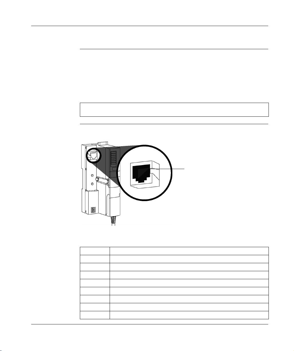
Introduction The fieldbus interface on the STB NIP 2212 is the point of connection between an
Advantys STB island and the Ethernet LAN on which the island resides. This
fieldbus interface is also called the Ethernet port.
The fieldbus interface is a 10Base-T port with an RJ-45 female connector. Category
5 (CAT5) twisted pair electrical wiring, either shielded or unshielded (STP/UTP), is
used to connect the STB NIP 2212 to the Ethernet baseband.
Note: Because the Ethernet port is configured for Modbus over TCP/IP services (SAP 502),
the Advantys configuration software can run over the fieldbus interface on the STB NIP 2212.
Fieldbus
(Ethernet) Port
The interface for 10Base-T connections is located on the front of the STB NIP 2212
NIM toward the top:
1
8
eight-pin connector
The RJ-45 connector is an eight-pin female connector. The eight pins connect
horizontally along the top. Pin 8 has the leftmost position, and pin 1 is the rightmost.
The pin-out for the RJ-45 complies with the information in the following table:
Pin Description
1tx+
2tx-
3rx+
4 reserved
5 reserved
6rx-
7 reserved
8 reserved
26
890USE17700 April 2004
Page 27

The STB NIP 2212 NIM
Communications
Cable and
Connector
About STP/UTP
Cabling
The required communications cable is either shielded (STP) or unshielded (UTP)
electrical, twisted pair CAT5 cable. The cable used with the STB NIP 2212 must
terminate with an eight-pin male connector.
The CAT5 cable recommended for connecting the STB NIP 2212 to an Ethernet
LAN has the following characteristics:
standard description max. length application data rate connector to the
fieldbus interface
10Base-T 24-gauge,
twisted pair
Note: There are many 8-pin male connectors that are compatible with the RJ-45 fieldbus
interface on the STB NIP 2212. Refer to the Transparent Factory Network Design and
Cabling Guide (490 USE 134 00) for a list of approved connectors.
100 m (328 ft) data
transmission
10 Mbits/s eight-pin male
Note: The technical specifications for CAT5 cable are defined by FCC Part 68, EIA/
TIA-568, TIA TSB-36, and TIA TSB-40.
Select STP or UTP cable according to the noise level in your environment:
z
Use STP cabling in high electrical noise environments.
z
UTP cabling is acceptable in low electrical noise environments.
890USE17700 April 2004 27
Page 28
The STB NIP 2212 NIM
Rotary Switches
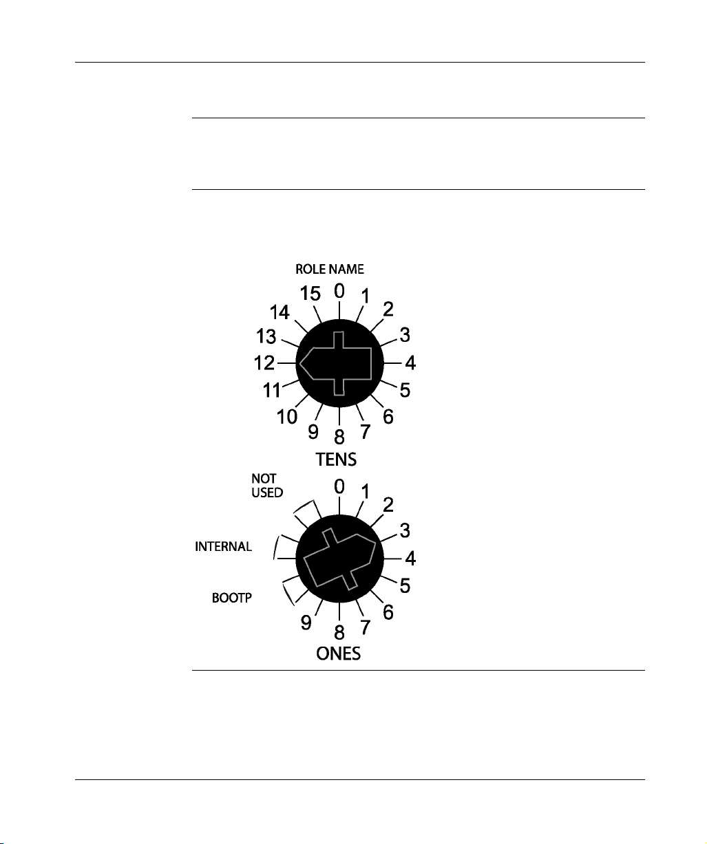
Introduction The STB NIP 2212 is a single node on an Ethernet LAN and, in turn, the Internet.
An STB NIP 2212 must have a unique IP address. The two rotary switches on the
NIM provide a simple, easy way to assign an IP address to the STB NIP 2212.
Physical
Description
The two rotary switches are positioned one above the other on the front of the
STB NIP 2212. The upper switch represents the tens digit, and the lower switch
represents the ones digit:
28
890USE17700 April 2004
Page 29
The STB NIP 2212 NIM
Summary of
Valid IP Address
Settings
Each rotary switch position that you can use to set a valid IP address is marked on
the STB NIP 2212 housing (See Physical Description, p. 28). The following
information summarizes the valid address settings:
z
For a switch-set role name, select a numeric value from 00 to 159. You can use
both switches:
z
On the upper switch (tens digit), the available settings are 0 to 15.
z
On the lower switch (ones digit), the available settings are 0 to 9.
The numeric setting is appended to the STB NIP 2212 part number, e.g.,
STBNIP2212_123, and a DHCP server assigns it an IP address.
z
For a BootP-served IP address (See Server-Assigned IP Addresses, p. 62),
select either of the two BOOTP positions on the bottom switch.
z
If you set the bottom switch to either of the two INTERNAL positions, the
IP address will be assigned by one of the following methods:
z
if the STB NIP 2212 is direct from the factory, it has no software set
IP parameters and will use a MAC-based IP address (See Deriving an
IP Address from a Media Access Control (MAC) Address, p. 61).
z
a fixed IP address using the STB NIP 2212 web configuration pages (See
Web-Based Configuration Options, p. 71)
z
a web-configured role name (See Configuring a Role Name, p. 82) in
association with a DHCP server
Note: For information about how the STB NIP 2212 prioritizes IP addressing
options, refer to the IP parameterization flow chart (See Determining the
IP Address, p. 63).
Note: The STB NIP 2212 requires a valid IP address to communicate on the
Ethernet network and with a host. You must power cycle the STB NIP 2212 to
configure the STB NIP 2212 with an IP address set with these rotary switches.
890USE17700 April 2004 29
Page 30
The STB NIP 2212 NIM
LED Indicators
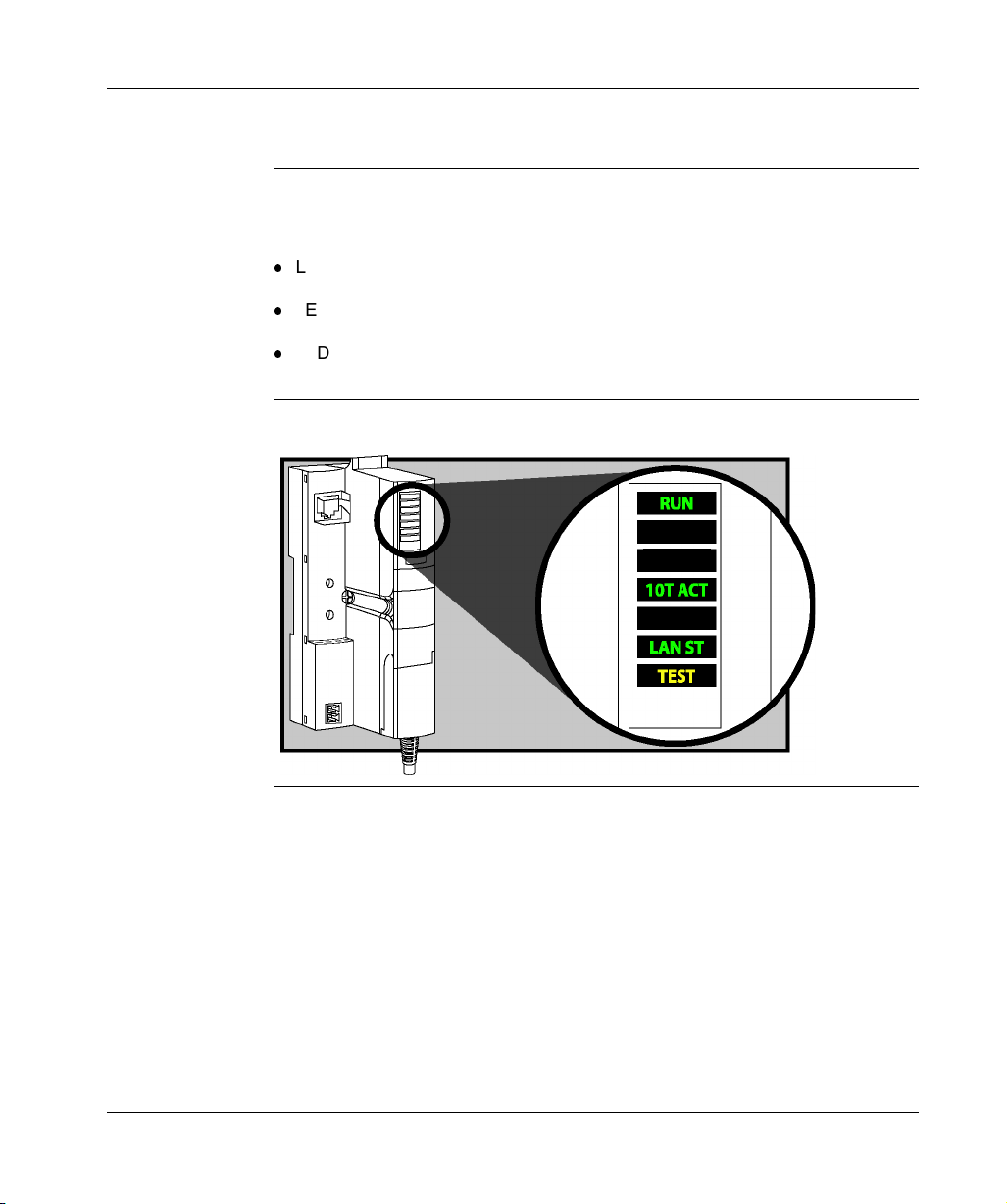
Introduction Six LEDs on the STB NIP 2212 NIM visually indicate the operational status of the
island bus on an Ethernet LAN. The LED array is located toward the top of the NIM
front bezel:
z
LED 10T ACT (See Ethernet Communications LEDs, p. 31) indicates whether
the Ethernet LAN and the Ethernet port are healthy and alive.
z
LED LAN ST (See Ethernet Communications LEDs, p. 31) indicates events on
the Ethernet LAN.
z
LEDs RUN, PWR, ERR, and TEST indicate activity on the island and/or events
on the NIM.
Description The illustration shows the six LEDs used by the Advantys STB NIP 2212:
PWR
ERR
30
890USE17700 April 2004
Page 31

The STB NIP 2212 NIM
Ethernet
Communications
LEDs
Advantys STB
Communications
LEDs
The 10T ACT and the STATUS indicate the conditions described in the following
table:
Label Pattern Meaning
10T ACT (green)
LAN ST (green)
on The network is alive and healthy.
off The network is not alive and not healthy.
steady on The Ethernet LAN is operational.
steady off No MAC address found.
blinking Initializing the Ethernet network.
blink: 3 No link pulse detected.
blink: 4 Duplicate IP address detected.
blink: 5 Obtaining IP address (See The IP Address
Assignment Process, p. 63).
blink: 6 Using the default IP address (See Deriving an
IP Address from a Media Access Control (MAC)
Address, p. 61).
The table that follows describes the island bus condition(s) communicated by the
LEDs, and the colors and blink patterns used to indicate each condition.
RUN
(green)
blink: 2 blink: 2 blink: 2 The island is powering up (self test in progress).
off off off The island is initializing—it is not started.
blink: 1 off off The island has been put in the pre-operational state by
off blink: 8 off The contents of the removable memory card is invalid.
blinking
(steady)
blinking off on Auto-configuration data is being written to Flash
off blink: 6 off The NIM detects no I/O modules on the island bus.
ERR (red) TEST
(yellow)
blink: 3 The NIM is reading the contents of the removable
on The NIM is overwriting its Flash memory with the card’s
off off The NIM is configuring (See Configuring the Island
Meaning
the RST button—it is not started.
memory card (See Using the STB XMP 4440 Optional
Removable Memory Card to Configure the Island Bus,
p. 53).
configuration data. (See 1.)
Bus, p. 45) or auto-configuring (See AutoConfiguration, p. 49) the island bus—the bus is not
started.
memory. (See 1.)
890USE17700 April 2004 31
Page 32

The STB NIP 2212 NIM
RUN
(green)
ERR (red) TEST
(yellow)
Meaning
off blink: 2 off Configuration mismatch detected after power up—at
least one mandatory module does not match; the island
bus is not started.
off blink: 2 off Assignment error—the NIM has detected a module
assignment error; the island bus is not started.
blink: 5 Internal triggering protocol error.
off blinking
(steady)
off Fatal error—Because of the severity of the error, no
further communications with the island bus are
possible and the NIM stops the island. The following
are fatal errors:
z
significant internal error
z
module ID error
z
auto-addressing (See Auto-Addressing, p. 46)
failure
z
mandatory module (See Configuring Mandatory
Modules, p. 153) configuration error
z
process image error
z
auto-configuration/configuration (See AutoConfiguration, p. 49) error
z
island bus management error
z
receive/transmit queue software overrun error
on off off The island bus is operational.
on blink 3 off At least one standard module does not match—the
island bus is operational with a configuration mismatch.
on blink: 2 off Serious configuration mismatch (when a module is
pulled from a running island)—the island bus is now in
pre-operational mode because of one or more
mismatched mandatory modules.
blink: 4 off off The island bus is stopped (when a module is pulled
from a running island)—no further communications
with the island are possible.
off on off Fatal error—internal failure.
[any] [any] on Test mode is enabled—the configuration software or
an HMI panel can set outputs. (See 2.)
1 The TEST LED is on temporarily during the Flash overwrite process.
2 The TEST LED is on steadily while the device connected to the CFG port is in control.
32
890USE17700 April 2004
Page 33

The STB NIP 2212 NIM
The CFG Interface
Purpose The CFG port is the connection point to the island bus for either a computer running
the Advantys configuration software or an HMI panel.
Physical
Description
The CFG interface is a front-accessible RS-232 interface located behind a hinged
flap on the bottom front of the NIM:
The port uses a male eight-pin HE-13 connector.
Port Parameters The CFG port supports the set of communication parameters listed in the following
table. If you want to apply any settings other than the factory default values, you
must use the Advantys configuration software:
Parameter Valid Values Factory Default Settings
bit rate (baud) 2400 / 4800 / 9600 / 19200 /
38400/ 57600
data bits 7/8 8
stop bits 1/2 1
parity none/odd/even even
Modbus communications mode RTU/ASCII RTU
9600
Note: To restore all of the CFG port’s communication parameters to their factory
default settings, push the RST button (See The RST Button, p. 55) on the NIM. Be
aware, however, that this action will overwrite all of the island’s current
configuration values with factory default values.
You can also password protect a configuration, thereby putting the island in
protected mode (See Protecting Configuration Data, p. 164). If you do this,
however, the RST button will be disabled and you will not be able to use it to reset
the port parameters.
890USE17700 April 2004 33
Page 34

The STB NIP 2212 NIM
Connections An STB XCA 4002 programming cable must be used to connect the computer
running the Advantys configuration software or a Modbus-capable HMI panel to the
NIM via the CFG port.
The following table describes the specifications for the programming cable:
Parameter Description
model STB XCA 4002
function connection to device running Advantys configuration
software
connection to HMI panel
communications protocol Modbus (either RTU or ASCII mode)
cable length 2 m (6.23 ft)
cable connectors eight-receptacle HE-13 (female)
nine-receptacle SUB-D (female)
cable type multiconductor
34
890USE17700 April 2004
Page 35

The STB NIP 2212 NIM
The Power Supply Interface
Introduction The NIM’s built-in power supply requires 24 VDC from an external SELV-rated
power source. The connection between the 24 VDC source and the island is the
male two-pin connector illustrated below.
Physical
Description
Power from the external 24 VDC supply comes in to the NIM via a two-pin connector
located at the bottom left of the module:
1 connector 1–24 VDC
2 connector 2–common voltage
890USE17700 April 2004 35
Page 36

The STB NIP 2212 NIM
Connectors Use either:
z
a screw type power connector, available in a kit of 10 (model STB XTS 1120)
z
a spring clamp power connector, available in a kit of 10 (model STB XTS 2120)
The following illustrations show two views of each power connector type. A front and
back view of the STB XTS 1120 screw type connector is shown on the left, and a
front and back view of the STB XTS 2120 spring clamp connector is shown on the
right:
1 STB XTS 1120 screw-type power connector
2 STB XTS 2120 spring clamp power connector
3 wire entry slot
4 screw clamp access
5 spring clamp actuation button
36
Each entry slot accepts a wire in the range 0.14 to 1.5 mm2 (28 to 16 AWG).
Each connector has a 3.8 mm (0.15 in) pitch between the entry slots.
890USE17700 April 2004
Page 37

The STB NIP 2212 NIM
Logic Power
Introduction Logic power is a 5 VDC power signal on the island bus that the I/O modules require
for internal processing. The NIM has a built-in power supply that provides logic
power. The NIM sends the 5 V logic power signal across the island bus to support
the modules in the primary segment.
External Source
Power
Input from an external 24 VDC power supply (See Characteristics of the External
Power Supply, p. 39) is needed as the source power for the NIM’s built-in power
supply. The NIM’s built-in power supply converts the incoming 24 V to 5 V of logic
power. The external supply must be rated safety extra low voltage (SELV-rated).
CAUTION
IMPROPER GALVANIC ISOLATION
The power components are not galvanically isolated. They are intended
for use only in systems designed to provide SELV isolation between the
supply inputs or outputs and the load devices or system power bus. You
must use SELV-rated supplies to provide 24 VDC source power to the
NIM.
Failure to follow this precaution can result in injury or equipment
damage.
890USE17700 April 2004 37
Page 38

The STB NIP 2212 NIM
Logic Power
Flow
The figure below shows how the NIM’s integrated power supply generates logic
power and sends it across the primary segment:
5V
24 V
24 VDC
The figure below shows how the 24 VDC signal is distributed to an extension
segment across the island:
5V
24 V
24 VDC
5V
24 V
The logic power signal is terminated in the STB XBE 1000 module at the end of the
segment (EOS).
Island Bus Loads The built-in power supply produces 1.2 A of current for the island bus. Individual
STB I/O modules generally draw a current load of between 50 and 90 mA. (Consult
the Advantys STB Hardware Components Reference Guide (890 USE 172 00) for a
particular module’s specifications.) If the current drawn by the I/O modules totals
more than 1.2 A, additional STB power supplies need to be installed to support the
load.
38
890USE17700 April 2004
Page 39

The STB NIP 2212 NIM
Selecting a Source Power Supply for the Island’s Logic Power Bus
Logic Power
Requirements
Characteristics
of the External
Power Supply
An external 24 VDC power supply is needed as the source for logic power to the
island bus. The external power supply connects to the island’s NIM. This external
supply provides the 24 V input to the built-in 5 V power supply in the NIM.
The NIM delivers the logic power signal to the primary segment only. Special
STB XBE 1200 beginning-of-segment (BOS) modules, located in the first slot of
each extension segment, have their own built-in power supplies, which will provide
logic power to the STB I/O modules in the extension segments. Each BOS module
that you install requires 24 VDC from an external power supply.
The external power supply needs to deliver 24 VDC source power to the island. The
supply that you select can have a low range limit of 19.2 VDC and a high range limit
of 30 VDC. The external supply must be rated safety extra low voltage (SELV-rated).
The SELV-rating means that SELV isolation is provided between the power supply’s
inputs and outputs, the power bus, and the devices connected to the island bus.
Under normal or single-fault conditions the voltage between any two accessible
parts, or between an accessible part and the protective earth (PE) terminal for Class
1 equipment, will not exceed a safe value (60 VDC max.).
CAUTION
IMPROPER GALVANIC ISOLATION
The power components are not galvanically isolated. They are intended
for use only in systems designed to provide SELV isolation between the
supply inputs or outputs and the load devices or system power bus. You
must use SELV-rated supplies to provide 24 VDC source power to the
NIM.
Failure to follow this precaution can result in injury or equipment
damage.
890USE17700 April 2004 39
Page 40

The STB NIP 2212 NIM
Calculating the
Wattage
Requirement
The amount of power (See Logic Power Flow, p. 38) that the external power supply
must deliver is a function of the number of modules and the number of built-in power
supplies installed on the island.
The external supply needs to provide 13 W of power for the NIM and 13 W for each
additional STB power supply (like an STB XBE 1200 BOS module). For example, a
system with one NIM in the primary segment and one BOS module in an extension
segment would require 26 W of power.
For example, the figure below shows an extended island:
40
1 24 VDC source power supply
2 NIM
3 PDM
4 primary segment I/O modules
5 BOS module
6 first extension segment I/O modules
7 second extension segment I/O modules
8 island bus terminator plate
890USE17700 April 2004
Page 41

The STB NIP 2212 NIM
The extended island bus contains three built-in power supplies:
z
the supply built into the NIM, which resides in the leftmost location of the primary
segment
z
a power supply built into each of the STB XBE 1200 BOS extension modules,
which reside in the leftmost location of the two extension segments
In the figure, the external supply would provide 13 W of power for the NIM plus 13 W
for each of the two BOS modules in the extension segments (for a total of 39 W).
Note: If the 24 VDC source power supply also supplies field voltage to a power
distribution module (PDM), you must add the field load to your wattage calculation.
For 24 VDC loads, the calculation is simply amps x volts = watts.
Suggested
Devices
The external power supply is generally enclosed in the same cabinet as the island.
Usually the external power supply is a DIN rail-mountable unit.
For installations that require 72 W or less from a 24 VDC source power supply, we
recommend a device such as the ABL7 RE2403 Phaseo power supply from
Telemecanique, distributed in the United States by Square D. This supply is DIN railmountable and has a form factor similar to that of the island modules.
If you have room in your cabinet and your 24 VDC power requirements are greater
than 72 W, summable power supply options such as Schneider’s Premium
TSX SUP 1011 (26 W), TSX SUP 1021 (53 W), TSX SUP 1051 (120 W), or
TSX SUP 1101 (240 W) can be considered. These modules are also available from
Telemecanique and, in the United States, from Square D.
890USE17700 April 2004 41
Page 42

The STB NIP 2212 NIM
Module Specifications
Specifications
Detail
The general specifications for the STB NIP 2212, which is the Ethernet network
interface module (NIM) for an Advantys STB island bus, appear in the following
table:
General Specifications
dimensions width 40.5 mm (1.594 in)
height 130 mm (4.941 in)
depth 70 mm (2.756 in)
interface and
connectors
built-in power
supply
addressable
modules
supported
to the Ethernet LAN RJ-45 female connector
CAT5 STP/UTP twisted-pair, electrical
cable(s)
RS-232 (See Physical
Description, p. 33) port for device
running the Advantys
configuration software or an HMI
panel (See The HMI Blocks in the
Island Data Image, p. 170)
to the external 24 VDC power
supply
input voltage 24 VDC nominal
input power range 19.2 ... 30 VDC
internal current supply 400 mA@ 24 VDC, consumptive
output voltage to the island bus 5 VDC nominal
output current rating 1.2 A @ 5 VDC
isolation no internal isolation
per segment 16 maximum
per island 32 maximum
eight-pin connector HE-13
two-pin connector (See The Power
Supply Interface, p. 35)
2% variation due to temperature drift,
intolerance, or line regulation
1% load regulation
<
50 mΩ output impedance up to
100 kHz
Isolation must be provided by an
external 24 VDC source power supply,
which must be SELV-rated.
42
890USE17700 April 2004
Page 43

General Specifications
segments
supported
primary (required) one
extension (optional) six maximum
standards Ethernet conformance IEEE 802.3
Transparent Ready
B20
implementation classification
HTTP Port 80 SAP
SNMP Port 161 SAP
Modbus over TCP/IP Port 502 SAP
MTBF 200,000 hours GB (ground benign)
electromagnetic compatibility
IEC 1131
(EMC)
The STB NIP 2212 NIM
890USE17700 April 2004 43
Page 44

The STB NIP 2212 NIM
44
890USE17700 April 2004
Page 45

Configuring the Island Bus
3
At a Glance
Introduction The information in this chapter describes the auto-addressing and auto-
configuration processes. An Advantys STB system has an auto-configuration
capability in which the current, actual assembly of I/O modules on the island bus is
read every time that the island bus is either powered up or reset. This configuration
data is saved to Flash memory automatically.
The removable memory card is discussed in this chapter. The card is an
Advantys STB option for storing configuration data offline. Factory default settings
can be restored to the island bus I/O modules and the CFG port by engaging the
RST button.
The NIM is the physical and logical location of all island bus configuration data and
functionality.
What's in this
Chapter?
890USE17700 April 2004 45
This chapter contains the following topics:
Topic Page
Auto-Addressing 46
Auto-Configuration 49
Installing the STB XMP 4440 Optional Removable Memory Card 50
Using the STB XMP 4440 Optional Removable Memory Card to Configure the
Island Bus
The RST Button 55
RST Functionality 56
53
Page 46

Configuring the Island Bus
Auto-Addressing
Introduction Each time that the island is powered up or reset, the NIM automatically assigns a
unique island bus address to each module on the island that will engage in data
exchange. All Advantys STB I/O modules and preferred devices engage in data
exchange and require island bus addresses.
About the Island
Bus Address
Addressable
Modules
An island bus address is a unique integer value in the range 0 through 127 that
identifies the physical location of each addressable module on the island.
Addresses 0, 124, 125 and 126 are reserved. Address 127 is always the NIM’s
address. Addresses 1 through 123 are available for I/O modules and other island
devices.
During initialization, the NIM detects the order in which modules are installed and
addresses them sequentially from left to right, starting with the first addressable
module after the NIM. No user action is required to address these modules.
The following module types require island bus addresses:
z
Advantys STB I/O modules
z
preferred devices
z
standard CANopen devices
Because they do not exchange data on the island bus, the following are not
addressed:
z
bus extension modules
z
PDMs such as the STB PDT 3100 and STB PDT 2100
z
empty bases
z
termination plate
46
890USE17700 April 2004
Page 47

Configuring the Island Bus
An Example For example, if you have an island bus with eight I/O modules:
1 NIM
2 STB PDT 3100 24 VDC power distribution module
3 STB DDI 3230 24 VDC two-channel digital input module
4 STB DDO 3200 24 VDC two-channel digital output module
5 STB DDI 3420 24 VDC four-channel digital input module
6 STB DDO 3410 24 VDC four-channel digital output module
7 STB DDI 3610 24 VDC six-channel digital input module
8 STB DDO 3600 24 VDC six-channel digital output module
9 STB AVI 1270 +/-10 VDC two-channel analog input module
10 STB AVO 1250 +/-10 VDC two-channel analog output module
11 STB XMP 1100 island bus termination plate
The NIM would auto-address it as follows. Note that the PDM and the termination
plate do not consume island bus addresses:
Module Physical Location Island Bus Address
NIM 1 127
STB PDT 3100 PDM 2 not addressed—does not exchange data
STB DDI 3230 input 3 1
STB DDO 3200 output 4 2
STB DDI 3420 input 5 3
STB DDO 3410 output 6 4
STB DDI 3610 input 7 5
STB DDO 3600 output 8 6
STB AVI 1270 input 9 7
STB AVO 1250 output 10 8
890USE17700 April 2004 47
Page 48

Configuring the Island Bus
Associating the
Module Type
with the Island
Bus Location
As a result of the configuration process, the NIM automatically identifies physical
locations on the island bus with specific I/O module types. This feature enables you
to hot swap a failed module with a new module of the same type.
48
890USE17700 April 2004
Page 49

Configuring the Island Bus
Auto-Configuration
Introduction All Advantys STB I/O modules are shipped with a set of predefined parameters that
allow an island to be operational as soon as it is initialized. This ability of island
modules to operate with default parameters is known as auto-configuration. Once
an island bus has been installed, assembled, and successfully parameterized and
configured for your fieldbus network, you can begin using it as a node on that
network.
Note: A valid island configuration does not require the intervention of the optional
Advantys configuration software.
About AutoConfiguration
Customizing a
Configuration
Auto-configuration occurs when:
z
You power up an island for the first time.
z
You push the RST button (See The RST Button, p. 55).
As part of the auto-configuration process, the NIM checks each module and
confirms that it has been properly connected to the island bus. The NIM stores the
default operating parameters for each module in Flash memory.
You can customize the operating parameters of the I/O modules, create reflex
actions, add preferred modules and/or CANopen standard devices to the island bus,
and customize other island capabilities.
890USE17700 April 2004 49
Page 50

Configuring the Island Bus
Installing the STB XMP 4440 Optional Removable Memory Card
Introduction The STB XMP 4440 removable memory card is a 32-kbyte subscriber identification
module (SIM) that lets you store (See Saving Configuration Data, p. 163), distribute,
and reuse custom island bus configurations. If the island is in unprotected (edit)
mode (See Protection Feature, p. 164) and a removable memory card containing a
valid island bus configuration is inserted in the NIM, the configuration data on the
card overwrites the configuration data in Flash memory, and is adopted when the
island starts up. If the island is in protected mode, the island ignores the presence
of a removable memory card.
The removable memory card is an optional Advantys STB feature.
Note: Network configuration data, such as the fieldbus baud setting cannot be
saved to the card.
Physical
Description
The card measures 25.1 mm (0.99 in) wide x 15 mm (0.59 in) high x 0.76 mm
(0.30 in) thick. It is shipped as a punch-out on a credit-card-sized plastic card, which
measures 85.6 mm (3.37 in) wide x 53.98 mm (2.13 in) high.
Note: Keep the card free of contaminants and dirt.
CAUTION
LOSS OF CONFIGURATION—MEMORY CARD DAMAGE OR
CONTAMINATION
The card’s performance can be degraded by dirt or grease on its
circuitry. Contamination or damage may create an invalid configuration.
z
Use care when handling the card.
z
Inspect for contamination, physical damage, and scratches before
installing the card in the NIM drawer.
z
If the card does get dirty, clean it with a soft dry cloth.
Failure to follow this precaution can result in injury or equipment
damage.
50
890USE17700 April 2004
Page 51

Configuring the Island Bus
Installing the
Card
Use the following procedure to install the card:
Step Action
1 Punch out the removable memory card from the plastic card on which it is
shipped.
removable memory card
Make sure that the edges of the card are smooth after you punch it out.
2 Open the card drawer on the front of the NIM. If it makes it easier for you to work,
you may pull the drawer completely out from the NIM housing.
3 Align the chamfered edge (the 45° corner) of the removable memory card with
the one in the mounting slot in the card drawer. Hold the card so that the chamfer
is in the upper left corner.
4 Seat the card in the mounting slot, applying slight pressure to the card until it
snaps into place. The back edge of the card must be flush with the back of the
drawer.
5 Close the drawer.
890USE17700 April 2004 51
Page 52

Configuring the Island Bus
Removing the
Card
Use the following procedure to remove the card from the card drawer. As a handling
precaution, avoid touching the circuitry on the removable memory card during its
removal.
Step Action
1 Open the card drawer.
2 Push the removable memory card out of the drawer through the round opening
at the back. Use a soft but firm object like a pencil eraser.
52
890USE17700 April 2004
Page 53

Configuring the Island Bus
Using the STB XMP 4440 Optional Removable Memory Card to Configure the
Island Bus
Introduction A removable memory card is read when an island is powered on. If the configuration
data on the card is valid, the current configuration data in Flash memory is
overwritten.
A removable memory card can be active only if an island is in edit mode. If an island
is in protected mode (See Protecting Configuration Data, p. 164), the card and its
data are ignored.
Configuration
Scenarios
The following discussion describes several island configuration scenarios that use
the removable memory card. The scenarios assume that a removable memory card
is already installed in the NIM:
z
initial island bus configuration
z
replace the current configuration data in Flash memory in order to:
z
apply custom configuration data to your island
z
temporarily implement an alternative configuration; for example, to replace an
island configuration used daily with one used to fulfill a special order
z
copying configuration data from one NIM to another, including from a failed NIM
to its replacement; the NIMs must run the same fieldbus protocol
z
configuring multiple islands with the same configuration data
Note: Whereas writing configuration data from the removable memory card to the
NIM does not require use of the optional Advantys configuration software, you must
use this software to save (write) configuration data to the removable memory card
in the first place.
Edit Mode Your island bus must be in edit mode to be configured. In edit mode, the island bus
can be written to as well as monitored.
Edit mode is the default operational mode for the Advantys STB island:
z
A new island is in edit mode.
z
Edit mode is the default mode for a configuration downloaded from the Advantys
configuration software to the configuration memory area in the NIM.
890USE17700 April 2004 53
Page 54

Configuring the Island Bus
Initial
Configuration
and Reconfiguration Scenarios
Use the following procedure to set up an island bus with configuration data that was
previously saved (See Saving Configuration Data, p. 163) to a removable memory
card. You can use this procedure to configure a new island or to overwrite an
existing configuration. Note: Using this procedure will destroy your existing
configuration data.
Step Action Result
1 Install (See Installing the
STB XMP 4440 Optional
Removable Memory Card,
p. 50) the removable
memory card in its drawer
in the NIM.
2 Power on the new island
bus.
The configuration data on the card is checked. If the
data is valid, it is written to Flash memory. The system
restarts automatically, and the island is configured with
this data. If the configuration data is invalid, it is not
used and the island bus will stop.
If the configuration data was unprotected, the island
bus remains in edit mode. If the configuration data on
the card was password-protected (See Protecting
Configuration Data, p. 164), your island bus enters
protected mode at the end of the configuration
process.
Note: If you are using this procedure to reconfigure an
island bus and your island is in protected mode, you
can use the configuration software to change the
island’s operational mode to edit.
Configuring
Multiple Island
Buses with the
Same Data
54
You can use a removable memory card to make a copy of your configuration data;
then use the card to configure multiple island buses. This capability is particularly
advantageous in a distributed manufacturing environment or for an OEM (original
equipment manufacturer).
Note: The island buses may be either new or previously configured, but the NIMs
must all run the same fieldbus protocol.
890USE17700 April 2004
Page 55

Configuring the Island Bus
The RST Button
Summary The RST function is basically a Flash memory overwriting operation. This means
that RST is functional only after the island has been successfully configured at least
once. All RST functionality is performed with the RST button, which is enabled only
in edit mode.
Physical
Description
Engaging the
RST Button
The RST button is located immediately above the CFG port (See Physical
Description, p. 33), and behind the same hinged cover:
RST button
Holding down the RST button for two seconds or longer causes Flash memory to be
overwritten, resulting in a new configuration for the island.
CAUTION
UNINTENDED EQUIPMENT OPERATION/CONFIGURATION
OVERWRITTEN—RST BUTTON
Do not attempt to restart the island by pushing the RST button. Pushing
the RST button will cause the island bus to reconfigure itself with factory
default operating parameters.
Failure to follow this precaution can result in injury or equipment
damage.
To engage the RST button, it is recommended that you use a small screwdriver with
a flat blade no wider than 2.5 mm (.10 in). Do not use a sharp object that might
damage the RST button, nor a soft item like a pencil that might break off and jam the
button.
890USE17700 April 2004 55
Page 56

Configuring the Island Bus
RST Functionality
Introduction The RST function allows you to reconfigure the operating parameters and values of
an island by overwriting the current configuration in Flash memory. RST functionality
affects the configuration values associated with the I/O modules on the island, the
operational mode of the island, and the CFG port parameters.
The RST function is performed by holding down the RST button (See The RST
Button, p. 55) for at least two seconds. The RST button is enabled only in edit mode.
In protected mode (See Protecting Configuration Data, p. 164), the RST button is
disabled; pressing it has no effect.
Note: Network settings, such as the fieldbus baud and the fieldbus node ID, remain
unaffected.
CAUTION
UNINTENDED EQUIPMENT OPERATION/CONFIGURATION DATA
OVERWRITTEN—RST BUTTON
Do not attempt to restart the island by pushing the RST button. Pushing
the RST button (See The RST Button, p. 55) causes the island bus to
reconfigure itself with factory default operating parameters.
Failure to follow this precaution can result in injury or equipment
damage.
RST
Configuration
Scenarios
56
The following scenarios describe some of the ways that you can use the RST
function to configure your island:
z
Restore factory-default parameters and values to an island, including to the I/O
modules and the CFG port (See Port Parameters, p. 33).
z
Add a new I/O module to a previously auto-configured (See Auto-Configuration,
p. 49) island.
If a new I/O module is added to the island, pressing the RST button will force the
auto-configuration process. The updated island configuration data is
automatically written to Flash memory.
890USE17700 April 2004
Page 57

Configuring the Island Bus
Overwriting
Flash Memory
with Factory
Default Values
The Role of the
NIM in this
Process
The following procedure describes how to use the RST function to write default
configuration data to Flash memory. Follow this procedure if you want to restore
default settings to an island. This is also the procedure to use to update the
configuration data in Flash memory after you add an I/O module to a previously
auto-configured island bus. Because this procedure will overwrite the configuration
data, you may want to save your existing island configuration data to a removable
memory card before pushing the RST button.
Step Action
1 If you have a removable memory card installed, remove it (See Removing the
Card, p. 52).
2 Ensure that your island is in edit mode.
3 Hold the RST button (See The RST Button, p. 55) down for at least two seconds.
The NIM reconfigures the island bus with default parameters as follows:
Stage Description
1 The NIM auto-addresses (See Auto-Addressing, p. 46) the I/O modules on the
island and derives their factory-default configuration values.
2 The NIM overwrites the current configuration in Flash memory with configuration
data that uses the factory-default values for the I/O modules.
3 It resets the communication parameters on its CFG port to their factory-default
values (See Port Parameters, p. 33).
4 It re-initializes the island bus and brings it into operational mode.
890USE17700 April 2004 57
Page 58

Configuring the Island Bus
58
890USE17700 April 2004
Page 59

IP Parameters
4
At a Glance
Introduction The information in this chapter describes how IP parameters are assigned to the
STB NIP 2212.
What's in this
Chapter?
This chapter contains the following topics:
Topic Page
How the STB NIP 2212 Obtains IP Parameters 60
The IP Address Assignment Process 63
890USE17700 April 2004 59
Page 60

IP Parameters
How the STB NIP 2212 Obtains IP Parameters
Summary As a node on a TCP/IP network, the STB NIP 2212 requires a valid 32-bit IP
address. The IP address can be:
z
the MAC-based default IP address
z
assigned by an Internet server
z
customer-configured using the STB NIP 2212 web pages (See About the
Embedded Web Server, p. 67)
Note: Refer to the IP parameters flow chart (See The IP Address Assignment
Process, p. 63) for information about how the STB NIP 2212 prioritizes IP address
assignment options.
60
890USE17700 April 2004
Page 61

IP Parameters
Deriving an
IP Address from
a Media Access
Control (MAC)
Address
The 32-bit default IP address for the STB NIP 2212 is composed of the last four
octets of its 48-bit Media Access Control (MAC) address. The MAC address, or
Institute of Electrical and Electronics Engineers, Inc. (IEEE) global address is
assigned at the factory. The MAC address for an STB NIP 2212 is located on the
front bezel under the Ethernet port (See External Features of the STB NIP 2212,
p. 24).
A MAC address is stored in hexadecimal format. The numbers in the MAC address
must be converted from hexadecimal to decimal notation to derive the default
IP address. Use the following steps:
Step Action
1 A MAC address comprises six pairs of hex values, e.g., 00 00 54 10 01 02.
Ignore the first two pairs: 00 00.
2 Identify a pair, e.g., 54.
3 Multiply the first number, 5 by 16. (5 x 16 = 80).
4 Add the second number, 4 (80 + 4 = 84).
Note: There are many resources for converting hex numbers to decimal numbers.
We recommend using the Windows calculator in scientific mode.
Note: If you set the lower rotary switch to either INTERNAL position (See Rotary
Switches, p. 28) and no IP parameters have been assigned from the
STB NIP 2212 web site, the STB NIP 2212 is configured with its derived default
address when it is powered on.
890USE17700 April 2004 61
Page 62

IP Parameters
MAC-Based
IP Address
Example
In the following example, the hex pairs in the example IEEE global address
(MAC address) 54.10.2D.11 are converted into a decimal number in the derived
IP address. The derived IP address is 84.16.45.17, so this becomes the default
IP address for the example STB NIP 2212:
Hex Pair Decimal Conversion
5 x 16 = 80 + 4= 84
10
1 x 16 = 16 + 0 = 16
2D
2 x 16 = 32 + 13 = 45
D = 13 in hex
11
1 x 16 = 16 + 1 = 17
Server-Assigned
IP Addresses
Role Name A role name is a combination of the Ethernet NIM part number STBNIP2212 and a
A server-assigned IP address may be obtained from either a BootP or a DHCP
server. A BootP server must be invoked using either BOOTP position on the lower
rotary switch (See Physical Description, p. 28). A DHCP-served IP address is
associated with a role name.
numeric value, e.g., STBNIP2212_123.
A role name may be assigned in one of two ways:
z
using the numeric settings (00 to 159) on the rotary switches (See Physical
Description, p. 28)
z
setting the lower rotary switch to an INTERNAL position, powering on the
STB NIP 2212, and completing the Role Name web page (See Sample
Role Name Web Page, p. 82).
CustomerConfigured
IP Address
62
If your STB NIP 2212 does not have a role name, you can configure an IP address
directly on the Configured IP web page (See Sample Configured IP Web Page,
p. 72). Set the lower rotary switch to an INTERNAL position, power on the
STB NIP 2212, and complete the web page.
890USE17700 April 2004
Page 63

The IP Address Assignment Process
IP Parameters
Determining the
IP Address
As shown in the following flow chart, the STB NIP 2212 performs a sequence of
checks to determine an IP address:
STOP—invalid position
yes
yes
yes
using role name in
no connection
allowed
role name
configured in
memory
yes
DHCP request
memory
no
BootP request
receive
IP parameters
yes
yes
read switch-set
role
DHCP request
using switch-set
role name
switch
position
USED
NOT
no
switch
position
BOOTP
no
switch
position
INTERNAL
no
name
yes
yes
no
yes
are
IP parameters
valid
yes
assign IP parameters
890USE17700 April 2004 63
receive
and validate
IP parameters
assign configured
IP parameters
Initialization complete
yes
no
configured
IP parameters
present
no
default IP address
constructed from MAC
Page 64

IP Parameters
IP Address
Software
Priorities
Frame Format
Priorities
The IP addressing methods for the STB NIP 2212 are prioritized in the order listed
in the following table. Note: The lower rotary switch must be set to either of the two
INTERNAL positions (See Rotary Switches, p. 28):
Priority IP Address Method
1 role name
2 configured IP parameters (set up on the Configured IP web page (See Sample
Configured IP Web Page, p. 72))
3 MAC-based default IP address (See Deriving an IP Address from a Media
Access Control (MAC) Address, p. 61)
The STB NIP 2212 supports communications in the Ethernet II and 802.3 frame
formats. Ethernet II is the default.
When communicating with a BootP server, the STB NIP 2212 first makes three
requests using the Ethernet II frame format; then it makes three requests using the
802.3 frame format. The interval between each request is one second.
When communicating with a DHCP server, the STB NIP 2212 makes eight requests
using the Ethernet II frame format; then it makes eight requests using the 802.3
frame format.
64
890USE17700 April 2004
Page 65

STB NIP 2212 Web Server
5
At a Glance
Introduction The STB NIP 2212 includes an embedded web server that is described in this
chapter.
What's in this
Chapter?
This chapter contains the following sections:
Section Topic Page
5.1 Introduction to the Embedded Web Server 66
5.2 Web Server Configuration Options 70
5.3 Web Server Security 85
5.4 Web Server Diagnostic Options 91
5.5 SNMP Services 102
890USE17700 April 2004 65
Page 66

STB NIP 2212 Web Server
5.1 Introduction to the Embedded Web Server
At a Glance
Introduction This section introduces the STB NIP 2212 embedded web server.
What's in this
Section?
This section contains the following topics:
Topic Page
About the Embedded Web Server 67
Properties Web Page 69
66
890USE17700 April 2004
Page 67

STB NIP 2212 Web Server
About the Embedded Web Server
Introduction The STB NIP 2212 includes a Hypertext Transfer Protocol (HTTP) based
embedded web server. Via a web browser (See Browser Requirements, p. 67),
configuration and diagnostic data about the island node can be viewed and
selectively edited.
Initialization of
the HTTP Server
At the end of the IP parameterization process (See Determining the IP Address,
p. 63), the STB NIP 2212 is initialized as an HTTP server, and its web pages are
available to view and/or edit.
Browser
Requirements
Either the Netscape Navigator browser, version 4.0 or greater, or the Internet
Explorer browser, version 4.0 or greater, must be used with the STB NIP 2212 web
pages.
Security The STB NIP 2212 web site has three layers of security:
z
The initial security is provided by the default HTTP password. You should replace
this password with your own web access password (See Web Access Password
Protection, p. 86).
z
Knowledge of your web access password allows read-only access to your
STB NIP 2212 web site.
z
Knowledge of the configuration password (See Configuration Password
Protection, p. 89) allows read/write access to your STB NIP 2212 web site.
Web Page Help Page-level help is available for every STB NIP 2212 web page. To display the help
text for a page, click on the word Help. It is located at the top of the web page and
to the right of the STB NIP 2212 banner.
890USE17700 April 2004 67
Page 68

STB NIP 2212 Web Server
Accessing the
STB NIP 2212
Web Site
Product Support
Web Page
Use the following steps to access the STB NIP 2212 web site:
Step Action Result
1 Go to your url: http://configured IP address The STB NIP 2212
home page is displayed.
2 Enter your language preference. English is the default
language.
z
If your language preference is English, click on the
Enter button.
z
To select a different language, click on its name, e.g.,
Deutsche. Then click on the Enter button.
3 Type the user name and the web access password for
your STB NIP 2212 site. Then click on the OK button to
proceed.
Note: The default user name and password are
Both are case-sensitive. They should be changed (See
Web Access Password Protection, p. 86) for your
STB NIP 2212 web site.
4 To navigate to a different web page, click on its tab. For
example, for information about how to contact the
STB NIP 2212 product support team, click on the Support
tab.
USER.
The web access
password dialog box is
displayed.
The STB NIP 2212
Properties (See
Properties Web Page,
p. 69) page is displayed.
The Support web page
(See Product Support
Web Page, p. 68) is
displayed.
Information about how to contact Schneider Electric about your STB NIP 2212
product is available from the Support web page. A sample Support page appears in
the following figure:
68
890USE17700 April 2004
Page 69

STB NIP 2212 Web Server
Properties Web Page
Introduction The Properties web page displays STB NIP 2212 statistics, such as the version of
the kernel and the executive, as well as the communications protocols for which the
STB NIP 2212 is configured.
Sample
Properties Web
Page
1
The Properties page is displayed automatically after the HTTP server authenticates
the user name and web access password. A sample Properties page is shown in the
following figure:
2 3
5
4
6
1 STB NIP 2212 banner. The role name (if configured) and the IP address in current use
display in the web banner.
2 Click on the word Home to return to the STB NIP 2212 home page.
3 Click on the word Help to display the help text for this web page.
4 The network activity icon indicates which communications protocols are active. The top
light represents HTTP, the middle light Modbus, and the bottom light FTP. If a protocol is
active, the light representing it is lit. For more information, drag the mouse over the light.
5 Navigation tabs.
6 Schneider Electric copyright information.
890USE17700 April 2004 69
Page 70

STB NIP 2212 Web Server
5.2 Web Server Configuration Options
At a Glance
Introduction The information in this section describes the configuration options supported by the
STB NIP 2212 embedded web server.
What's in this
Section?
This section contains the following topics:
Topic Page
Configuration Web Page 71
Configuring an IP Address for the STB NIP 2212 72
Configuring Master Controllers 77
Master Configurator Web Page 79
Configuring a Role Name 82
70
890USE17700 April 2004
Page 71

STB NIP 2212 Web Server
Configuration Web Page
Introduction The web-based resources that are available for configuring the STB NIP 2212 are
listed as options on the Configuration menu. The specific web page for each feature
is linked to a menu option.
Web-Based
Configuration
Options
Accessing the
Configuration
Menu
The Configuration menu appears in the following figure:
Use step 1 in the following procedure to access the Configuration menu. Then use
step 2 to navigate to the specific web page for the configuration option:
Step Action Result
1 Click on the Configuration tab. The Configuration menu is displayed.
2 Click on the option that you want to use,
e.g., Master Configurator (See Master
Configurator Web Page, p. 79).
The web page for the configuration
option that you selected is displayed.
890USE17700 April 2004 71
Page 72

STB NIP 2212 Web Server
Configuring an IP Address for the STB NIP 2212
Introduction To communicate as a node on the Internet, the fieldbus (Ethernet) port on the
STB NIP 2212 must be configured with a valid IP address. The IP address must be
unique on the Ethernet LAN on which the STB NIP 2212 resides.
One of the available IP address assignment methods (See How the STB NIP 2212
Obtains IP Parameters, p. 60) is to configure an IP address yourself. A customer
configured IP address is set up on the Configured IP web page.
Sample
Configured IP
Web Page
A sample Configured IP web page appears in the following figure:
72
890USE17700 April 2004
Page 73

STB NIP 2212 Web Server
IP Parameters The IP address for the STB NIP 2212 has the four parameters, which are described
in the following table:
Parameter Description
IP address Unique 32-bit address assigned to every node on the Internet.
subnet mask The subnet mask is 32 bits assigned with the IP address of a host. The
contiguous 1’s of the mask are used to separate the network portion from the
host portion of the address. When the subnet mask is applied to the source
and destination addresses, it determines if the target host is on the local
subnet or on a remote network.
gateway The default gateway, typically a router, is where the host sends frames that
are bound for remote networks after the subnet mask compare.
frame type Data format used by a protocol. For example, the STB NIP 2212 can use
either the Ethernet II or the IEEE 802.3 frame format. Ethernet II is the default.
Note: The IP address for the STB NIP 2212 is written in dotted decimal format.
Using the
Command
Buttons
The following table describes how to use the command buttons on the Configured IP
web page:
To ... Click on ...
Display the IP address stored in Flash memory Reset
Display the MAC-based, derived default IP address. Default
Save the IP address displayed on the Configured IP web page. Save
Configure the STB NIP 2212 with the IP address displayed on the
Configured IP web page.
Reboot
890USE17700 April 2004 73
Page 74

STB NIP 2212 Web Server
Assigning a
Configured
IP Address to the
STB NIP 2212
Use the following procedure to configure an IP address for the STB NIP 2212. Note:
Your STB NIP 2212 cannot have a role name.
Step Action Comment
1 Set the lower rotary switch to an INTERNAL
position (See Physical Description, p. 28),
and power cycle the STB NIP 2212.
2 If your STB NIP 2212, has a role name, you
must remove it using the Role Name web
page (See Configuring a Role Name, p. 82).
3 Open the STB NIP 2212 web site.
4 Click on the Configuration tab to display the
Configuration menu.
5 Select the Configured IP option.
6 In the IP address field, type the IP address
that you want to use in dotted decimal
format.
7 Click on the Save button to save the address
to Flash memory and in RAM.
8 Click on the Configuration tab to return to the
Configuration menu.
9 Select the Reboot option (See About the
Reboot Option, p. 76).
10 At the Reboot now? prompt, click on the OK
button.
11 Click on the OK button at the confirmation
prompt, "Are you sure?"
If no role name is assigned, skip
step 2.
If the address is valid, it will appear in
the banner at the top of each
STB NIP 2212 web page.
Note: The LAN ST LED (See
Ethernet Communications LEDs,
p. 31) on the NIM blinks four times if
the IP address is a duplicate.
Your STB NIP 2212 restarts. The
IP address that you set up on the web
is the active IP address for the island.
74
890USE17700 April 2004
Page 75

STB NIP 2212 Web Server
Restoring
Default
Parameters from
the Web
Use the following procedure to reconfigure the STB NIP 2212 with its default
IP parameters (See Deriving an IP Address from a Media Access Control (MAC)
Address, p. 61) from the web. Note: Your STB NIP 2212 cannot have a role name.
Step Action Comment
1 Open the STB NIP 2212 web site.
2 Click on the Configuration tab to display
the Configuration menu.
3 Select the Configured IP option. The Configured IP web page (See Sample
Configured IP Web Page, p. 72) opens.
4 Click on the Default button. The IP address parameters are restored
to their default values.
The address is based on the 48-bit MAC
address that was programmed into the
STB NIP 2212 when it was manufactured.
5 Click on the Save button to save the
address to Flash memory and in RAM.
6 Click on the Configuration tab to return
to the Configuration menu.
7 Select the Reboot option (See About the
Reboot Option, p. 76).
8 At the Reboot now? prompt, click on the
OK button.
9 Click on the OK button at the
confirmation prompt, "Are you sure?"
Note: The LAN ST LED (See Ethernet
Communications LEDs, p. 31) on the NIM
blinks six times if the STB NIP 2212
default address is in use. If the address is
a duplicate, the LAN ST LED blinks four
times.
890USE17700 April 2004 75
Page 76

STB NIP 2212 Web Server
About the
Reboot Option
The reboot operation will configure the STB NIP 2212 with IP parameters assigned
on the web. Information about the reboot operation appears in the following figure:
76
890USE17700 April 2004
Page 77

STB NIP 2212 Web Server
Configuring Master Controllers
Introduction Any controller on the Ethernet network has the potential to become the master of an
island on that network. Mastery can be obtained on a first-come/first-serve basis.
The STB NIP 2212 allows you to pre-assign mastery to as many as three specific
controllers on the network. If one of these assigned controllers is connected, it will
take mastery over any unassigned controllers, even if an unassigned controller has
connected to the island first. To assign one or more master controllers, use the
Master Controller web page.
Understanding
Processing
Mastery
Fields on the
Master
Controller Web
Page
A controller that has mastery over an island has the ability to write to the island’s
output process image and to change operating parameters on the island nodes..
Typically, the first controller to request write access is granted mastery. If another
master attempts to write to the island while the first controller has mastery, the NIM
sends an error message and access is denied.
If a master controller has been configured on the Master Controller web page (See
Sample Master Controller Web Page, p. 78), a write request from it will pre-empt
processing mastery from any other device during its reservation time.
To pre-assign one or more (up to three) master controllers for the STB NIP 2212,
identify them by their IP addresses:
Field Name Description
Master x ID* The unique IP address (See How the STB NIP 2212 Obtains IP Parameters,
p. 60) for a master controller.
reservation
time
holdup time The amount of time in ms that output modules will hold their current state
* If you do not enter an IP address, then write access to the NIM will be obtained by the first
master that writes to it.
The amount of time in ms allocated to a master controller for writing to the
STB NIP 2212. Other controllers attempting to write to the STB NIP 2212
while the master is connected will receive an error message.
The default reservation time is 60,000 (1 min). Each time the master writes to
the NIM, the reservation time is reset to 60,000.
without an update by a Modbus write command (See List of Supported
Commands, p. 135). When the module hold-up time out expires, the outputs
will be driven to their defined fallback states (See Island Fallback Scenarios,
p. 161).
Note: The holdup time must be defined via the Master Controller web page.
Holdup time out parameters and values are stored in nonvolatile Flash
memory.
890USE17700 April 2004 77
Page 78

STB NIP 2212 Web Server
Setting Up
Master
Controllers for
the Island
Sample Master
Controller Web
Page
Use the following procedure to configure a master controller for the STB NIP 2212:
Step Action
1 Click on the Configuration tab to display the Configuration menu.
2 Select the Master Controller option.
3 Type the IP address for each master controller (up to three) that you want to set
up.
4 Type a value for the reservation time (0 ... 120000 ms). This is the amount of
time allocated to any master controller. The default setting is 60000 ms (1 min).
5 Type a value in ms for the holdup time. The default setting is 1000 ms. (1 sec).
The valid values are:
z
values in the range 300 ... 120,000 ms.
z
a value of 0 ms signifiying indefinite hold up time
Note: You must enter the holdup value via the web page.
6 Click on the Save button to store information about the master controller in the
STB NIP 2212’s Flash memory and in RAM.
A sample Master Controller web page is shown in the following figure:
78
890USE17700 April 2004
Page 79

Master Configurator Web Page
STB NIP 2212 Web Server
What Is a Master
Configurator?
The master configurator of an Advantys STB island controls the configuration data
for all of the I/O modules during its reservation time (See Fields on the Master
Configurator Web Page, p. 80). The configuration master must run the Advantys
configuration software. The configuration master can connect to either the fieldbus
(Ethernet) interface (See Fieldbus (Ethernet) Port, p. 26) or the CFG port (See The
CFG Interface, p. 33) on the STB NIP 2212.
Note: The master configurator of an Advantys STB island must be set up on the
Master Configurator web page.
The configuration master of an Advantys STB island can be a:
z
local host that resides on the same Ethernet LAN as the island
z
remote host that communicates with the Ethernet LAN on which the island
resides
z
device connecting to the STB NIP 2212, serially, via the CFG port
The master configurator is identified on the Master Configurator web page as
follows:
z
A master configurator running over the network is identified by its IP address.
z
A configuration master connecting to the CFG port is specified as serial (See
Fields on the Master Configurator Web Page, p. 80).
A master configurator will pre-empt configuration mastery for the Advantys STB
island from any other configurator during its reservation time.
890USE17700 April 2004 79
Page 80

STB NIP 2212 Web Server
Fields on the
Master
Configurator
Web Page
Configuring a
Master
Configurator for
the Island
The fields on the Master Configurator web page are described in the following table:
Field Legal Values Description
Protocol IP The IP address (See How the STB NIP 2212 Obtains
IP Parameters, p. 60) of the master configurator on the
Ethernet LAN.
serial The master configurator is attached to the CFG port on the
STB NIP 2212.
disabled Disabled is the default setting for this feature.
If selected, the master configurator feature is disabled.
However, devices normally capable of configuring the island
will perform as designed.
reservation
time
0 ... 120000 ms,
with a 1 ms
resolution time
The amount of time in ms allocated to a master for writing
configuration data to the STB NIP 2212. Other masters
attempting to configure the island during this time will receive
an error message.
The default reservation time is 60,000 ms (1 min).
Reservation time is self-renewing.
Use the following procedure to configure a master configurator for an Advantys STB
island:
Step Action
1 Click on the Configuration tab to display the Configuration menu.
2 Select the Master Configurator option.
3 To identify the master configurator, do one of the following:
z
Click on the radio button next to the IP option and type in the IP address for
the master configurator communicating via the fieldbus (Ethernet) port (See
STB NIP 2212 Network Interface, p. 26), e.g., 139.158.2.38 (See Sample
Master Configurator Web Page, p. 81).
z
For a master configurator attached to the STB NIP 2212’s CFG port (See
The CFG Interface, p. 33), click on the radio button next to the Serial option.
z
To disable this feature, click on the radio button next to the Disabled (default)
option.
4 Type a value for the reservation time (0 ... 120000 ms). This is the amount of
time allocated to the master configurator for writing configuration data to the
island. The default setting is 60000 ms (1 min).
5 Click on the Save button to store the information about the master configurator
in the STB NIP 2212’s Flash memory and in RAM.
80
890USE17700 April 2004
Page 81

STB NIP 2212 Web Server
Sample Master
Configurator
Web Page
A sample Master Configurator web page is shown in the following figure:
890USE17700 April 2004 81
Page 82

STB NIP 2212 Web Server
Configuring a Role Name
Introduction You can assign, edit, or delete a role name for an STB NIP 2212 on the Role Name
web page. A role name comprises the STBNIP2212 part number, an underscore (_),
and three numeric characters, e.g., STBNIP2212_002.
A role name is the priority IP address assignment method used by the
STB NIP 2212 (See The IP Address Assignment Process, p. 63). If a role name is
assigned, the IP address for the STB NIP 2212 is always associated with it. You will
not be able to assign a configured IP (See Customer-Configured IP Address, p. 62)
or the default IP address (See Deriving an IP Address from a Media Access Control
(MAC) Address, p. 61), unless you remove the role name first.
Sample
Role Name Web
Page
A sample Role Name web page is shown below:
82
890USE17700 April 2004
Page 83

STB NIP 2212 Web Server
Configuring a
Role Name
Use the following procedure to create or edit a role name for the STB NIP 2212:
Step Action Comment
1 Set the lower rotary switch to an
INTERNAL position (See Physical
Description, p. 28), and power cycle the
STB NIP 2212.
2 Open the STB NIP 2212 web site.
3 Click on the Configuration tab to display
the Configuration menu.
4 Select the Role Name option.
5 Type or overtype the numeric part of the
role name with three numeric values. You
can use any numbers in the range
00 to 159 that are not already in use on
the same Ethernet LAN.
6 Click on the Save button to save your role
name to the Flash memory and in RAM.
7 Click on the Configuration tab to return to
the Configuration menu.
8 Select the Reboot option (See About the
Reboot Option, p. 84).
9 At the Reboot now? prompt, click on the
OK button.
10 Click on the OK button at the confirmation
prompt, "Are you sure?"
The default role name is
STBNIP2212_000.
The role name will appear in the banner
at the top of each STB NIP 2212 web
page.
Note: Saving the role name, however,
does not configure the STB NIP 2212
with it. You must reboot the
STB NIP 2212 (see step 8) to configure
it with a role name and to have a
DHCP server ass ign an IP address (See
Server-Assigned IP Addresses, p. 62).
Your STB NIP 2212 restarts. It is
configured with the role name and an
IP address.
890USE17700 April 2004 83
Page 84

STB NIP 2212 Web Server
About the
Reboot Option
Deleting a Role
Name
The reboot operation will configure the STB NIP 2212 with a role name assigned on
the web. Information about the reboot operation appears in the following figure:
You must delete a role name before you can assign a configured IP address or the
default IP parameters. Use the following steps:
Step Action
1 Set the lower rotary switch to an INTERNAL position (See Physical Description,
p. 28), and power cycle the STB NIP 2212.
2 Open the STB NIP 2212 web site.
3 Click on the Configuration tab to display the Configuration menu.
4 Select the Role Name option.
5 Highlight the role name to select it. Then press the Delete key on your keyboard.
6 Click on the Save button.
Note: The role name is deleted from Flash memory.
84
890USE17700 April 2004
Page 85

STB NIP 2212 Web Server
5.3 Web Server Security
At a Glance
Introduction The information in this section describes how the HTTP default password, the web
access password, and the configuration password are used to protect the
STB NIP 2212 web site.
What's in this
Section?
This section contains the following topics:
Topic Page
Web Access Password Protection 86
Configuration Password Protection 89
890USE17700 April 2004 85
Page 86

STB NIP 2212 Web Server
Web Access Password Protection
Summary The STB NIP 2212 web site is password-protected. Initially, security for the
STB NIP 2212 web site is provided by a default user name and password. Any
visitor to your STB NIP 2212 site can view all of your information using the default
user name and password.
You will want to set up your own user name and password to protect your
STB NIP 2212 web site. Use the Change Web Access Password (See What Is the
Web Access Password?, p. 87) option.
Default User
Name and
Password
The default name and password for the STB NIP 2212 web site are:
z
default user name—USER
z
default password—USER
The user name and password are case-sensitive.
Correct entry of the default user name and password authorizes read-only access
to your STB NIP 2212 web site. The default (HTTP password) screen is shown in
the following figure:
86
890USE17700 April 2004
Page 87

STB NIP 2212 Web Server
What Is the Web
Access
Password?
The web access password is an eight-character, case-sensitive user name and
password that you assign. Your values will replace the default protection for your
STB NIP 2212 web site. All visitors to your site must correctly complete the web
access password dialog box, which is shown in the following figure. The web access
dialog box displays immediately after the STB NIP 2212 home page.
890USE17700 April 2004 87
Page 88

STB NIP 2212 Web Server
Setting Up the
Web Access
Login
Use the following procedure to set up your web access user name and password:
Step Action Result
1 Navigate to your url: http://configured IP address. The STB NIP 2212 home page is
displayed.
2 Enter your language preference. English is the
default language.
z
If your language preference is English, click on
the Enter button.
z
To select a different language, click on its
name, e.g., Deutsche. Then click on the Enter
button.
3 Type
4 Click on the OK button. The STB NIP 2212 Properties
5 Click on the Security tab. The Security menu is displayed.
6 Select the Change Web Access Password option. The Change Web Access
7 Type the new user name.
8 Type the user name again as the value for the
9 In the New Password field, type your web access
10 Type the password again in the Confirm New
11 Click on the Save button. The web access user name and
USER, using all uppercase letters, in the user
name field and then, again, in the password field.
The user name can have a maximum of eight
alphanumeric characters. You can also use an
underscore (_).
The characters are case-sensitive.
Confirm New User Name field.
password.
The password can have a maximum of eight
alphanumeric characters. You can also use an
underscore (_).
The characters are case-sensitive.
Password field.
The web access password dialog
box is displayed.
web page (See Sample
Properties Web Page, p. 69) is
displayed.
Password page is displayed.
password take effect
immediately.
88
890USE17700 April 2004
Page 89

STB NIP 2212 Web Server
Configuration Password Protection
Introduction The configuration password controls read/write access from the STB NIP 2212 web
site to the physical module’s Flash memory. This password must be set up on the
Change Configuration Password web page.
Set
Configuration
Password
Procedure
Logging In and
Out
Use the following procedure to set up a configuration password for your
STB NIP 2212 web site:
Step Action Result
1 Click on the Security tab. The Security menu is
displayed.
2 Click on the Change Configuration Password
option.
3 In the New Password field, type your configuration
password.
The password must have six alphanumeric
characters. The characters are case-sensitive.
4 Type the password again in the Confirm New
Password field.
5 Click on the Save button. The configuration password
The Change Configuration
Password page is displayed.
takes effect immediately.
If you set up a configuration password, the following login procedure takes effect:
Step Action Result
1 Type the configuration password for your
web site next to the Logout button (See
Sample Login Prompt, p. 90).
Note: The password is case-sensitive.
2 Perform the write operation, e.g., configure
a role name from the Role Name web page
(See Configuring a Role Name, p. 82).
3 Click on the Logout button to end write
privileges on your web site.
The Login button toggles to Logout.
Your entire STB NIP 2212 web
session is now write enabled.
The Logout button toggles to Login.
Write protection for your web site is
restored.
890USE17700 April 2004 89
Page 90

STB NIP 2212 Web Server
Sample Login
Prompt
Synchronizing
the Web and
Advantys
Software
Configuration
Passwords
When active, the login prompt is displayed in the web banner (as shown in the
following figure). The six-character configuration password must be entered to
proceed:
The same password is used to authorize write privileges on the STB NIP 2212 web
pages and to configure an Advantys STB island bus with the Advantys configuration
software (See Protecting Configuration Data, p. 164).
If your island already has a configuration password via the Advantys configuration
software, you must use it as the configuration password for your STB NIP 2212 web
site, and vice versa.
90
890USE17700 April 2004
Page 91

STB NIP 2212 Web Server
5.4 Web Server Diagnostic Options
At a Glance
Introduction The information in this section describes the diagnostics options supported by the
STB NIP 2212 embedded web server.
What's in this
Section?
This section contains the following topics:
Topic Page
Diagnostics Web Page 92
Ethernet Statistics 93
STB NIP 2212 Registers Web Page 94
I/O Data Values Web Page 96
Island Configuration Web Page 98
Island Parameters Web Page 99
Error Log Web Page 100
890USE17700 April 2004 91
Page 92

STB NIP 2212 Web Server
Diagnostics Web Page
Introduction The web-based resources that are available for troubleshooting the STB NIP 2212
are listed as options on the Diagnostics menu. The web page for each feature is
linked to a menu option.
Diagnostics
Menu
Accessing the
Diagnostics
Menu
The Diagnostics menu appears in the following figure:
Use step 1 in the following procedure to access the Diagnostics menu. Then use
step 2 to navigate to the web page for a specific diagnostics option.
Step Action Result
1 Click on the Diagnostics tab. The Diagnostics menu is displayed.
2 Click on the option that you want to use,
e.g., NIM Registers (See STB NIP 2212
Registers Web Page, p. 94).
The web page for the option that you
selected is displayed.
92
890USE17700 April 2004
Page 93

STB NIP 2212 Web Server
Ethernet Statistics
Introduction The Ethernet Statistics web page reports status information and errors that are
related to data transmissions to and from the STB NIP 2212 over the Ethernet LAN.
Refresh Rate The statistics on this page are updated at the rate of one per second.
Sample Ethernet
Statistics Web
Page
A sample Ethernet Statistics web page appears in the following figure:
1
3
4
1 unique role name for this STB NIP 2212.
2 unique IP address for this STB NIP 2212.
3 unique MAC address for this STB NIP 2212.
4 Ethernet statistics—click on the Help button to display a description for each Ethernet
statistic.
5 Reset button—clicking on this button returns all of the counters to 0.
2
5
890USE17700 April 2004 93
Page 94

STB NIP 2212 Web Server
STB NIP 2212 Registers Web Page
Summary The NIM Registers web page will display information about specific Modbus
registers in the STB NIP 2212 process image. The registers to display are identified
by their Modbus register addresses.
Page Design The NIM Registers web page is designed to provide a shared view of the specified
Modbus registers (See The Data Image, p. 166). There is no limit to the number of
registers that can be displayed on this web page.
Customized and
Common Views
Using the
Command
Buttons
The NIM Registers web page is designed to provide a customized but common view
of the STB NIP 2212 process image to everyone viewing the web page.
z
Custom view—By supplying a personal variable name (maximum 10
characters) and an actual Modbus register location (See The Data Image,
p. 166), you can customize this page to show the data that is most important to
you.
z
Common view—However, only one view of the NIM Registers can be saved to
Flash memory.
After the display on the NIM Registers web page is written to Flash memory (by
clicking on the Save button on the page), the display on this web page is fixed,
providing a common view.
The following table describes how to use the command buttons on the NIM
Registers web page:
To ... Click on the ...
add a row to the display. Add button.
delete one or more row(s) from the display. checkbox in front of each row that you
want to delete; then, click on the Delete
button.
save the NIM registers’ information from the web
page to Flash memory.
Note: This operation will overwrite the "save"
space in Flash memory with the NIM registers’
data displayed on the web page.
Save button.
Format Feature The format feature allows you to select whether the content of the NIM registers is
displayed in decimal or hexadecimal notation.
94
890USE17700 April 2004
Page 95

STB NIP 2212 Web Server
Sample NIM
Registers Web
Page
A sample NIM Registers web page appears in the following figure:
5
7
1
4
5
2
3
6
1 10-character variable name
2 Modbus register number
3 current value for Modbus register 30090 is 0
4 checkbox
5 Add and Delete buttons
6 format preference—decimal or hexadecimal
7 Clicking on the Save button overwrites the designated (single) space in Flash memory with
the content of this web page.
890USE17700 April 2004 95
Page 96

STB NIP 2212 Web Server
I/O Data Values Web Page
Summary The I/O Data Values web page will display the values stored in the process image
output data area (See The Output Data Process Image, p. 119) and input data area
(See The Input Data and I/O Status Process Image, p. 120) for the I/O modules
currently assembled on the island bus. The order of information on this web page is
the order of the I/O module assembly, as determined by the auto-addressing (See
Auto-Addressing, p. 46) and auto-configuration (See Auto-Configuration, p. 49)
processes.
Page Design The I/O Data Values web page is designed to accommodate 16 Advantys STB I/O
modules (or 256 Modbus registers (See The Data Image, p. 166)). The number of
modules that can be accommodated will vary according to actual I/O modules
assembled on the island. For example, if there are multiple six-channel digital I/O
modules (STB DDI 3610s and/or STB DDO 3600s), STB AVI 1270s,
STB AVO 1250s, and a specialty module like the STB ART 0200, fewer than 16
modules can be represented on the I/O Data Values web page.
96
890USE17700 April 2004
Page 97

STB NIP 2212 Web Server
Sample I/O Data
Values Web Page
A sample I/O Data Values web page appears in the following figure:
3
5
2
1
4
6
8
7
1 module’s island bus node address
2 Advantys STB part number
3 Modbus register location(s) for input and status data
4 input values
5 format preference—decimal or hexadecimal
6 Modbus register location(s) for output data
7 output values
8 middle light is lit indicating Modbus activity
890USE17700 April 2004 97
Page 98

STB NIP 2212 Web Server
Island Configuration Web Page
Introduction The Island Configuration web page describes the configuration and operational
status (See Fault Detection, p. 132) of every module currently assembled on the
island bus. The modules are listed in order of their assembly starting with the
STB NIP 2212.
Sample Island
Configuration
Web Page
A sample Island Configuration web page appears in the following figure:
98
890USE17700 April 2004
Page 99

Island Parameters Web Page
STB NIP 2212 Web Server
Sample Island
Parameters Web
Page
The Island Parameters web page displays a read-only list of the island’s parameters
and their current values. A sample web page appears in the following figure:
890USE17700 April 2004 99
Page 100

STB NIP 2212 Web Server
Error Log Web Page
Introduction System-wide information collected while the Advantys STB island is operational is
reported on the Error Log web page.
Sample Error
Log Web Page
A sample Error Log web page appears in the following figure:
100
890USE17700 April 2004
 Loading...