

Page 1
Installation Instructions
INPUT
:
CLASS 2 POWER ONLY
24VAC , 0.42A, 10 VA, 50/60HZ
USE COPPER CONDUCTORS ONLY
MORE THAN ONE DISCONNECT SWITCH
MAY BE REQUIRED TO DE-ENERGIZE THIS
EQUIPMENT BEFORE SERVICING.
CAUTION
This equipment complies with part 15 of the FCC rules.
Operation is subject to the following two conditions.
(1) This device may not cause harmful interference.
(2) This device must accept any interference received,
including interference that may cause undesired
operation.
24 VAC
RET
RET
RET
IN 5
IN 4
IN 3
IN 2
IN 11
21
20
19
18
17
16
15
14
13
OUT4
OUT5
TRIAC REF
AO6
RET
A07
SHIELD
12
OUT3
2
3
4
5
6
7
8
9
10
11
(HIGH)
(LOW)
AIR FLOW
INPUT
UNIVERSAL
INPUTS
RS-485
PORT
ANALOG
OUTPUTS
0-10 VDC
DIGITAL
OUTPUTS
24V AC ,
0.5A
SMART
SENSOR
COM
COM
866-V
P1
(LO)
P2
(HI)
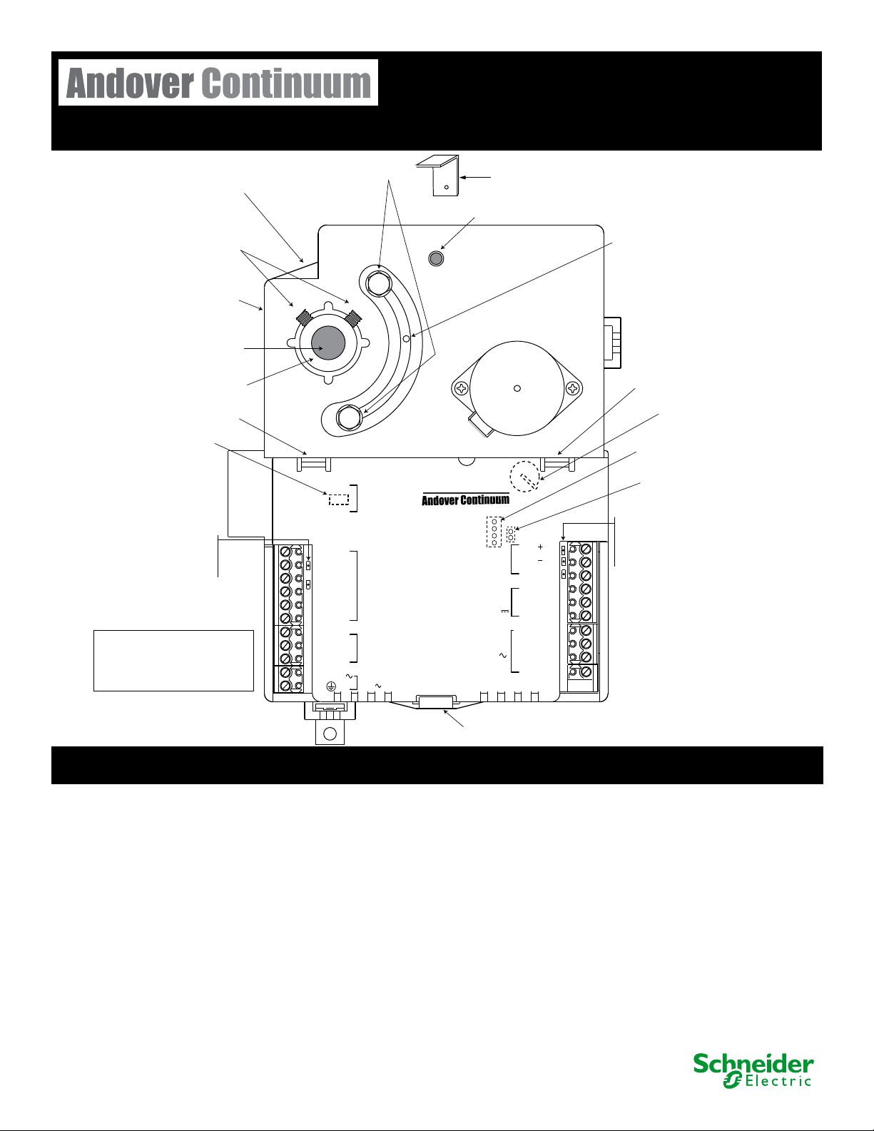
Mounting Clip
Alternative Damper Shaft
Mounting Screw Position
Adjustable Stops
Actuator Clutch Release
Damper Shaft
Hex Mounting Screws
Alternative Damper Shaft
Mounting Screw Position
Damper Shaft
Damper Shaft Collar
Cover Release
Velocity Sensor
Inputs
(Barbed fittings)
Cover Release
Damper Position Indicator
Alternate
Mounting Bracket
Mounting Bracket
Cover Release
Two CPU LEDs
Green = b3 controller
Yellow = i2 controller
TD LED = Yellow
RD LED = Green
Wireless LED = Red
Note: Input, Output, and
Smart Sensor connections will
vary per controller model.
Service Port Location
(Remove cover)
SPWR
4-Position Dipswitch
Battery Location
(Remove cover)
Jumper for Actuator
Direction
Wiring Requirements:
300V
8A
22 - 12AWG
6 inch-lb screw tourque
30-3001-985
i2/b3 865/866/885-V Controller
Rev G.4
i2/b3 865/866/885-V Controller Installation
To install the controller, follow these steps:
1. Check the mounting location for the Andover Continuum i2 or b3
865/866/885-V controller. The unit is typically mounted with the
controller extending down or to the right from the damper shaft.
However, the controller can be operated in any position within
the vertical plane.
Note: Installing the controller to the right (with the barbed
ttings pointing down) helps prevent condensate from
migrating into the on-board velocity sensor.
With a downward extension, the available area around the damp-
er shaft must measure 6” (160 mm) down from the lower edge
of the shaft, 4.5” (120 mm) to the right, 1.5” (40 mm) to the left
and 1.75” (45 mm) above the shaft. Ensure the location allows
enough clearance for servicing.
2. The actuator is designed to mount over a
3. If the exposed damper shaft is less than 2” (51 mm) but at least 1”
4. Select the mounting bracket location that provides the most stability
1
/2” (12.7 mm) diameter
shaft with a minimum of 2.5” (63.5 mm) of exposed shaft. If the
damper shaft diameter is less than 1/2” (12.7 mm) an adapter is
required. An adapter (p/n AM-135) is available from Schneider
Electric to allow mounting on 3/8” (9.5 mm) damper shaft. The
865/866/885-V controller will not work with larger damper shaft
diameters.
(25.4 mm) long, move the two damper shaft mounting screws to the
alternate lower damper shaft positions.
for the operation of the actuator. Position the mounting clip in the
desired mounting bracket. Do not insert the clip more than half-way
into the bracket. This allows the clip and the back of the actuator to
properly align with the VAV box.
© 2018 Schneider Electric, all rights reserved.
Page 2
i2/b3 865/866/885-V Controller Installation (continued)
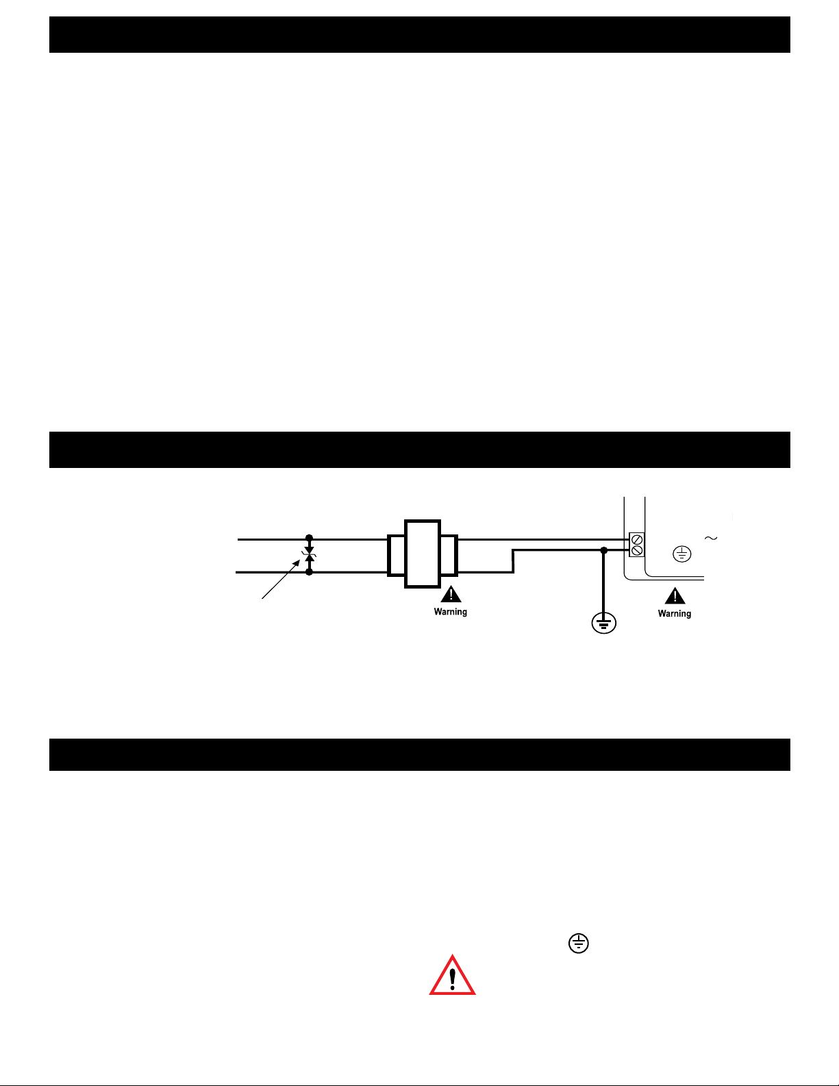
AC Line
Power
Optional Varistor
(Choose a voltage rating appropriate
to the input voltage applied.
For example, 130V or 250V)
24 VAC Step-Down
or Isolation Transformer
X1
X2
11
10 24VAC
Each controller on the network must have its own
24V Step-Down or Isolation Transformer. Be sure to
wire the secondary of the 24V Step-Down Transformer
exactly as shown. Pin 11 must be connected to the grounded
side of the secondary on all transformers used in the system.
Otherwise, damage to one or more controllers may result.
Class 2 power only!
5. Press and hold the green actuator clutch release and rotate the
VAV damper shaft by hand to the fully closed position. Note
whether the damper is rotated clockwise (CW) or counter-clockwise (CCW) to close.
6. Slip the controller over the damper shaft. Position the actuator
and, using a self tapping sheet metal screw, secure the mounting clip to the VAV box.
7. Next, press the actuator toward the box until the actuator comes
into contact with the VAV box, the mounting clip snaps into the
bracket, or the back of the actuator comes into contact with the
VAV box.
8. Press and hold the green actuator clutch release (see Figure on
cover page) and rotate the actuator collar to a nearly closed
position, the 5° index mark, if the damper shaft was rotated
counter-clockwise to close (Step 5). Rotate the actuator collar to
the 85° index mark if the damper shaft was rotated clockwise to
close (Step 5).
1
9. Tighten the two damper hex mounting screws using a
/8” hex
Allen wrench. The minimum torque required to secure the controller to the damper shaft depends on the shaft material. The
maximum torque for the socket screws is 30 inch-pounds (3.4
Nm).
AC Power Connection
Note: The damper should rotate freely when the clutch is released.
If it does not, the actuator may not be properly aligned with
the damper shaft – it may be necessary to repeat Steps 4
through 9 using a new orientation.
10. If the damper does not provide a mechanical stop in the open direction,
or it is not desirable to use the damper’s open stop, set the adjustable
stops on the 865/866/885-V controller to the desired position. Use a
1
/4” hex driver to adjust the screw stop on the controller.
Note: For the 866-V model only, you must calibrate the damper
position feedback reporting option before using. You
calibrate damper position feedback reporting by changing
the damper’s output attribute, LCDState, from DISABLED
to ENABLED. The attribute, OverrideValue, indicates the
damper position as a fractional value from 0 (at the closed
stop) to 1 (at the open stop).
Whenever the Actuator Clutch Release button is pressed and
the Actuator is moved manually, you need to recalibrate
damper position feedback reporting. During damper
calibration, the damper output will rotate from one end- stop
to the other and then return to its original position. It is also
recommended that you periodically recalibrate damper position
feedback reporting using a Plain English (PE) program.
Note: Use care when attaching power wiring to these connectors. They are not to be used as a strain relief.
The connectors cannot withstand excessive bending or exing.
Failing to install this transformer on remote controllers can damage it and other controllers on the network.
Wiring Rules
These modules are intended for installation
within the enclosure of another product.
Do not remotely ground any part of the input sensor wiring.
Remote grounds connected to the return terminal could make
the system operate incorrectly or damage the equipment.
The signal return is not true earth ground. It is an electronic
reference point necessary to interpret the sensor properly.
For reliable input operation, follow these input wiring guidelines:
• Never lay wires across the surface of a printed circuit board.
• Wires should never be within 1” or 25 mm of any component
on a printed circuit board.
• Use shielded input wire.
• Terminate the shield of the input wires at one end of the run
only — preferably at the end where your I/O module is located.
• When stripping wire, be careful not to drop small pieces of wire
inside the cabinet.
• Don’t run your input wiring in the same conduit with AC power.
• Don’t run your input wiring in the same conduit with your
output wiring.
Grounding the Controller
To insure proper operation of the controller, it must be connected to a
good earth ground. The connection must be made as close to the module
as possible.
Caution: Earth ground ( ) must be connected to avoid
module damage.
Removing the Plastic Battery Tab
Before operating the controller, open the cover and remove the
protective plastic battery tab. The battery location is shown in the
illlustration on the cover page.
Page 3
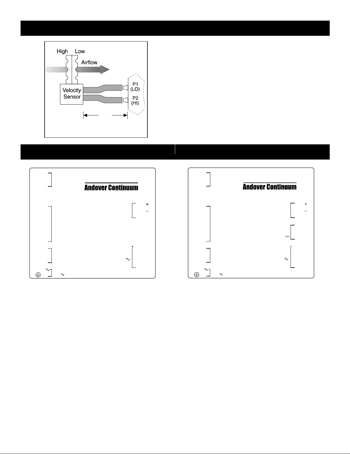
Connecting the Air Velocity Sensor
4’
(1.2 m)
Tubing (Max.)
1. Connect the low pressure side of the velocity sensor to the barbed
tting labeled P1 (LO) on the controller.
2. Connect the high pressure side of the velocity sensor to the tting
labeled P2 (HI) on the controller.
Notes: Use a recommended maximum length of 4’ (1.2 m) FRPE
plyetheylene tubing or 0.25” (6.34 mm) O.D. and 0.125”
(3.175 mm) I.D. Tygon tubing.
Do not expose the velocity sensor to moisture. If moisture
condensation is a potential problem, orient the tubing and
controller so that the barbed ttings are above the lowest
part of the tubing to create a moisture trap.
Connections for i2/b3 865-V Controller Connections for i2/b3 866-V Controller
(LOW)
(HIGH)
2
3
4
5
6
7
8
9
10
11
AIR FLOW
INPUT
CAUTION
IN 1 1
IN 2
RET
IN 3
IN 4
RET
SPWR
RET
IN 5
24 VAC
MORE THAN ONE DISCONNECT
SWITCH MAY BE REQUIRED
TO DE-ENERGIZE THIS EQUIPMENT
BEFORE SERVICING.
UNIVERSAL
INPUTS
This equipment complies with part 15
of the FCC rules. Operation is subject
to the following two conditions.
(1) This device may not cause harmful
interference.
(2) This device must accept any
interference received, including
interference that may cause
undesired operation.
SMART
SENSOR
USE COPPER CONDUCTORS ONLY
INPUT: CLASS 2 POWER ONLY
24VAC , 0.42 A, 10VA, 50/6 0HZ
865-V
PORT
0.5A
COM
COM
SHIELD
TRIAC REF
OUT5
OUT4
OUT3
RS-485
DIGITAL
OUTPUTS
24 VAC ,
Airow Input
One Low and one High connection
Universal Inputs
Four input and two return connections — terminals 1-6
Smart Sensor Bus Interface
One Smart Sensor connection — terminals 7-9
(LOW)
(HIGH)
18
17
16
15
14
13
12
2
3
4
5
6
7
8
9
10
11
AIR FLOW
INPUT
CAUTION
IN 1 1
IN 2
RET
IN 3
IN 4
RET
SPWR
RET
IN 5
24 VAC
MORE THAN ONE DISCONNECT
SWITCH MAY BE REQUIRED
TO DE-ENERGIZE THIS EQUIPMENT
BEFORE SERVICING.
UNIVERSAL
INPUTS
This equipment complies with part 15
of the FCC rules. Operation is subject
to the following two conditions.
(1) This device may not cause harmful
interference.
(2) This device must accept any
interference received, including
interference that may cause
undesired operation.
SMART
SENSOR
USE COPPER CONDUCTORS ONLY
INPUT: CLASS 2 POWER ONLY
24VAC , 0.42 A, 10VA, 50/6 0HZ
866-V
COM
RS-485
PORT
ANALOG
OUTPUTS
0-10 VDC
TRIAC REF
DIGITAL
OUTPUTS
24 VAC ,
0.5A
COM
SHIELD
A07
RET
AO6
OUT5
OUT4
OUT3
21
20
19
18
17
16
15
14
13
12
Airow Input
One Low and one High connection
Universal Inputs
Four input and two return connections — terminals 1-6
Smart Sensor Bus Interface
One Smart Sensor connection — terminals 7-9
Power Connection
One 24 VAC connection and ground — terminals 10-11
Digital Outputs
Three output connections and one triac reference — terminals 12-15
RS-485 Port
One port for a BACnet MS/TP or Innet connection — terminals 16-18
Power Connection
One 24 VAC connection and ground — terminals 10-11
Digital Outputs
Three output connections and one triac reference — terminals 12-15
Analog Outputs
Two analog outputs and one return connection — terminals 16-18
RS-485 Port
One port for a BACnet MS/TP or Innet connection — terminals 19-21
Page 4

Connections for i2/b3 885-V Controller
(LOW)
(HIGH)
2
3
4
5
AIR FLOW
INPUT
IN 1 1
UNIVERSAL
IN 2
INPUTS
RET
USE COPPER CONDUCTORS ONLY
24 VAC
INPUT: CLASS 2 POWER ONLY
24VAC , 0.42 A, 10VA, 50/6 0HZ
CAUTION
MORE THAN ONE DISCONNECT
SWITCH MAY BE REQUIRED
TO DE-ENERGIZE THIS EQUIPMENT
BEFORE SERVICING.
This equipment complies with part 15
of the FCC rules. Operation is subject
to the following two conditions.
(1) This device may not cause harmful
interference.
(2) This device must accept any
interference received, including
interference that may cause
undesired operation.
Physical Dimensions
885-V
OUTPUTS
24 VAC ,
RS-485
PORT
DIGITAL
0.5A
COM
COM
SHIELD
TRIAC REF
NOT USED
OUT4
OUT3
Airow Input
One Low and one High connection
Universal Inputs
Two input and one return connection — terminals 1-3
12
11
10
Power Connection
One 24 VAC connection and ground — terminals 4-5
Digital Outputs
Two output connections and one triac reference — terminals 6-9
9
8
7
6
RS-485 Port
One port for a BACnet MS/TP or Innet connection — terminals 10-12
Page 5

Wiring Digital Outputs
Switching Option - Triac “Form A” Ground Connection
Switching Option - Triac “Form A” Hot Connection
Switching Option - Triac “Form K” Ground Connection
Form A Triac Outputs
The new i2/b3 865/866-V controllers use three Form A triac output
terminals with a single triac reference. This conguration gives you
the exibility to wire the single triac reference as either a hot or
ground connection. On these new controllers, all three outputs must
be wired the same, as either hot or ground switch applications.
To make a hot switch connection, connect one of the output terminals
(OUTX, where X = 3, 4, or 5) to a load, and connect the Triac Reference to the incoming 24 VAC power.
i2/b3 865/866-V Controller
24 VAC Step-Down
AC Line
Power
Transformer
X1
X2
24 VAC
GND
Note: i2/b3 885-V Controller only has two digital outputs
DIGITAL
OUTPUTS
24VA C ,
TRIAC REF
15
OUT5
14
OUT4
13
0.5A
OUT3
12
Form K Triac Outputs
To create a Form K triac connection on the new i2/b3 865/866-V
controllers, make the individual connections from terminals 12
and 13 (OUT3 and OUT4), or use terminals 13 and 14 (OUT4 and
OUT5), with a common ground reference to terminal 15 (TRIAC
REF).*
i2/b3 865/866-V Controller
OUT4
Load
24 VAC Step-Down
Transformer
AC Line
Power
X1
X2
24 VAC
GND
Note: i2/b3 885-V Controller only has two digital outputs
To maintain Form K triac connections on the new i2/b3 885-V
controller, make the individual connections from terminals 6 and 7
(OUT3 and OUT4) with a common ground reference to terminal 9
(TRIAC REF).**
DIGITAL
OUTPUTS
24VA C ,
TRIAC REF
15
OUT5
14
OUT4
13
0.5A
OUT3
12
OUT3
Load
To make a ground switch connection, connect one of the output
terminals (OUTX, where X = 3, 4, or 5) to a load in series with the 24
VAC incoming power, and connect the Triac Reference to ground.
i2/b3 865/866-V Controller
24 VAC Step-Down
AC Line
Power
Transformer
X1
X2
24 VAC
GND
Note: i2/b3 885-V Controller only has two digital outputs
DIGITAL
OUTPUTS
24VA C ,
TRIAC REF
15
OUT5
14
OUT4
13
0.5A
OUT3
12
The new i2/b3 885-V controller, which only has two output terminal
connections, works the same, allowing for either two hot or ground
switch applications
Notes: * Use Andover Continuum CyberStation is set the lower
numbered digital output terminal to “tristate”.
** Terminal 8 is not used on the 885-V controller.
Wireless Network Operation
Cable Access Cut-Out on Cover
Service Port
To connect the controller to a Wireless Adapter, remove the cover and
connect the Andover Continuum Wireless Adapter cable to the Service Port and run the cable through the cable access opening (cut-out)
on the cover.
You must set two Continuum CyberStation software attributes for
wireless operation:
• The comm port must have the Default Mode set to “Wireless”.
• The software must “Learn” (discover) all the controllers on the
Continuum network.
These attributes are set using the CommPort Editor in CyberStation.
You need conguration privileges to congure a controller or comm
port.
Page 6

Specications
Dimensions
7.75” W x 6.25” L x 2.5” H (197 x 159 x 63.5 mm)
Operating Environment
Temperature: 32o to 122o F (0o to 50o C)
Humidity: 10 to 90% RH, non-condensing
Power Requirement
Power: 24 VAC, +10% -15%, 50/60 Hz, Class 2 Limited Power
Power Consumption: Less than 10VA
Overload Protection: Fused, MOV protected
Airow Input
Range: 0 to 1” W.C. (0-250 Pa)
Resolution: 0.0013” W.C. (0.33 Pa) @ 73o F (23o C)
Accuracy: +/- 0.05” W.C. (12.50 Pa) @ 73o F (23o C)
Communications
RS-485 port for implementing BACnet MS/TP or Innet connections, including:
• Three-position removable screw terminal
• Standard service port, four-position shrouded connector
• Support for wireless adapter
• LEDs:
TD = Transmit Enable
RD = Received Data
Wired/Wireless Field Bus
Universal Inputs
Connections:
• Model 865 — Four inputs and two returns
• Model 866 — Four inputs and two returns
• Model 885 — Two inputs and one return
Input Voltage Range: 0-5.115 VDC
Input Impedance: 10K to 5.120 V
Input Voltage Resolution: 5.0 mV
Digital Resolution: 10 bits
Input Voltage Accuracy: +/- 15 mV
Temperature Range: -30
Temperature Accuracy: +/- 1o F from -10o to +150o F
(+/- 0.56
o
to 230o F (-34o to 110o C)
o
C from -23o to +66o C)
Counter Frequency: 4 Hz @ 50% duty cycle
Input Protection: +/- 1000V transients
Input Filter: 16 Hz with a one pole RC lter
Connector: Removable, 5 mm screw terminal
4-Position Dipswitch (Model 865 and Model 866):
• One switch per input
• Four universal inputs
• Enables/Disables input pullup resistors
Smart Sensor Interface
Connections:
• Model 865 — One input, SPWR, and return
• Model 866 — One input, SPWR, and return
• Model 885 — Not Available
CPU LEDs
• Green = b3 software model (BACnet)
• Yellow = i2 software model (Innet)
Damper Shaft Mounting Screws
Torque Minimum: Varies according to shaft material
Torque Maximum: 30 inch-pounds (3.4 Nm)
Hex screws: 10-32 (with supplied hex wrench)
Damper Actuator (Motor)
Shaft Diameter: 1/2” (3/8” with AM-135 adapter)
Shaft Torque: 53 inch-pounds
Damper Speed: 180 sec.@ 60 Hz and 216 sec. @ 50 Hz; for 90
Adjustable end limits with two set screws
Motor:
• Type = 24 VAC synchronous
• Motor Protection: Mechanical clutch
• Manual clutch override with a push-button release
• Hardware position feedback (model 866-V only)
Actuator Jumper Settings (Tri-State for directional control)
Jumper Connected
• + (On) = Clockwise (CW)
• - (-On) = Counter Clockwise (CCW)
• O
Jumper Disconnected
• + (On) = Counter Clockwise (CCW)
• - (-On) = Clockwise (CW)
• O
Digital Outputs
Connections:
• Model 865 — Three triac output and one reference
• Model 866 — Three triac output and one reference
• Model 885 — Two triac output and one reference
SPST Accuracy: 0.1 second for pulse width modulation
Contact Ratings: 0.5A Maximum, 24VAC
Connector: Removable, 5 mm screw terminal
Analog Outputs
Connections:
o
• Model 865 — Not Available
• Model 866 — Two analog output and one return
• Model 885 — Not Available
Analog Output Channels Required: Two, Voltage only
Voltage Output Range: 0-10V
Output Source Current: 5 mA Maximum
Voltage Output Load: 2K Minimum Impedance
Voltage Output Resolution: 50 mV
Digital Resolution: 8 bits
Output Voltage Accuracy: 100 mV
Connector: Removable, 5 mm screw terminal
Terminal Contact Ratings
• 300V
• 8A
• 22 - 12AWG
• 6 inch-lb screw torque
Page 7

Regulatory Notices
Federal Communications Commission
FCC Rules and Regulations CFR 47, Part 15, Class A
This device complies with part 15 of the FCC Rules. Operation is subject to the following two conditions:
(1) This device may not cause harmful interference.
(2) This device must accept any interference received, including interference that may cause undesired operation.
Caution: The user that changes or makes modications not expressly approved by Schneider Electric for compliance could void the user’s authority to operate the equipment.
Industry Canada
ICES-003
This is a Class A digital device that meets all requirements of the Canadian Interference Causing Equipment Regulations.
CE - Compliance to European Union (EU)
2004/108/EC - EMC Directive
This equipment complies with the rules of the Ocial Journal of the European Communities specied in the EMC directive
89/336/EEC governing the Self Declaration of the CE Marking for the European Union.
C-Tick (Australian Communications Authority (ACA))
This equipment carries the C-Tick label and complies with EMC and radio communications regulations of the Australian Communications Authority (ACA), governing the Australian and New Zealand (AS/NZS) communities.
WEEE - Directive of the European Union (EU)
This equipment and its packaging carry the waste of electrical and electronic equipment (WEEE) label, in compliance with European Union (EU)
Directive 2002/96/EC, governing the disposal and recycling of electrical and electronic equipment in the European community.
and UL listed product for the United States and Canada, Open Energy Management
Related Documentation
Document Document Number
i2/b3 865/866/885-V Controller Retrot Guide 30-3001-988
i2 Controller Technical Reference 30-3001-861
b3 and b4920 Controller Technical Reference 30-3001-862
b3xxx PICS statements — contact Schneider Electric Technical Support
Page 8

 Loading...