

Page 1
Operation Manual
Smart-UPS™
Uninterruptible Power Supply
750/1000/1500 VA
120/230 Vac
2200 VA
120 V ac
3000 VA
100/120/208/230 Vac
Rack-Mount 2U
Page 2

Overview
Product Description
The APC™ by Schneider Electric Smart-UPS™ product name is a high performance uninterruptible power supply
(UPS). The UPS provides protection for electronic equipment from utility power blackouts, brownouts, sags,
surges, small utility power fluctuations and large disturbances. The UPS also provides battery backup power for
connected equipment until utility power returns to safe levels or the batteries are fully discharged.
This user manual is available on the enclosed CD and on the APC by Schneider Electric web site, www.apc.com.
Safety and General Information
Read the Safety Guide included in the package before installing the UPS.
This unit is intended for indoor use only.
Do not operate this unit in direct sunlight, in contact with fluids, or where there is excessive dust or humidity.
Be sure the air vents on the UPS are not blocked. Allow adequate space for proper ventilation.
The battery typically lasts for two to five years. Environmental factors impact battery life. Elevated ambient
temperatures, poor quality utility power, and frequent short duration discharges will shorten battery life.
Connect the Smart-UPS power cable directly to a wall outlet. Do not use surge protectors or extension cords.
The batteries are heavy. Remove the batteries prior to installing the UPS in a rack.
Always install the external battery packs (XLBPs) at the bottom of the rack. The UPS must be installed above the
XLBPs.
Specifications
Environmental
Operating 0° to 40° C (32° to 104° F)
Temperature
Maximum
Elevation
Humidity
Storage -15° to 45° C (5° to 113° F)
charge UPS battery every six months
Operating 3,000 m (10,000 ft)
Storage 15,000 m (50,000 ft)
0% to 95% relative humidity, non-condensing
1Smart-UPS 750-3000 VA 100/120/208/230 Vac Rack-Mount
Page 3
Product Overview
su064
su062
su064
su0625
su0626
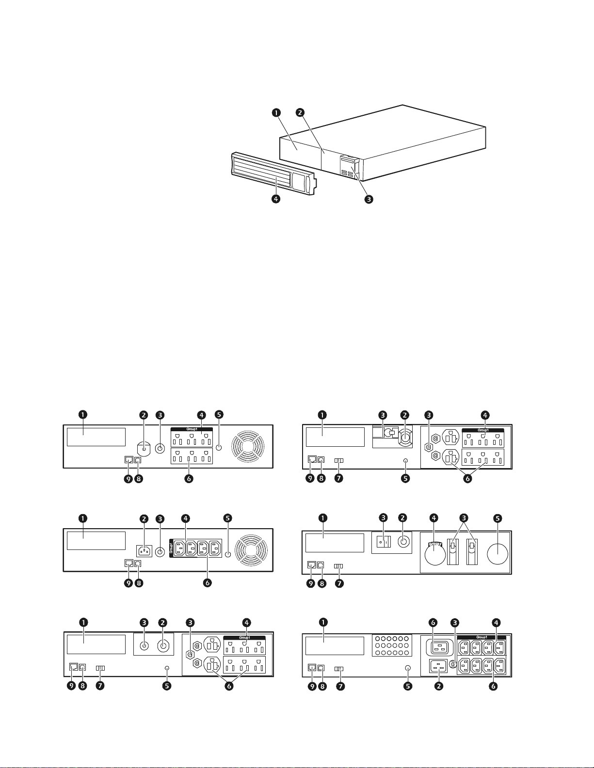
Front panel
Battery
Battery connector
*This will vary by model.
Display interface
Bezel
Rear panels
SmartSlot for optional NMC accessory card
UPS input
Circuit breaker/Overload protection
Controlled outlet group
Chassis ground connection screw (TVSS GND)
Outlets
EPO connector
USB port
RJ45 connector - serial UPS monitoring port
su0498a
750/1000 VA 120 Vac
1500 VA 100/120 Vac 3000 VA 100/120 Vac
4a
750/1000/1500 VA 230 Vac 3000 VA 208 Vac
5a
2200 VA 120 Vac 3000 VA 230 Vac
su0623a
4a
a
a
Smart-UPS 750-3000 VA 100/120/208/230 Vac Ra ck-Mount2
Page 4

Installation
UPS
For UPS installation info rmation, see the Smart-U PS Installation Guide that is included with the UPS.
The guide is also available on the enclosed CD and the APC by Schneider Electric web site at
www.apc.com.
Network Management Card
For installation information, see the user manual provided with the Network Management Card (NMC).
The user manual is also available on the APC by Schneider Electric web site at www.apc.com.
3Smart-UPS 750-3000 VA 100/120/208/230 Vac Rack-Mount
Page 5
Operation
Connect Equipment to the UPS
Note: The UPS will charge to 90% ca pac it y in t he fi rst three hours of normal op era ti on. Do
not expect full battery runtime capability during this initial charge period.
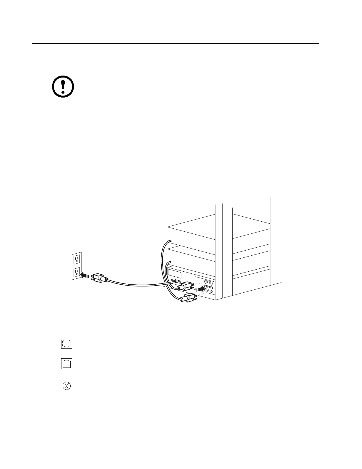
1. Connect equipment to the outlets on the rear panel of the UPS.
2. Connect the UPS to the building utility power. Connect the UPS to a two-pole, three-wire,
grounded source only.
3. Press the
equipment.
4. To use the UPS as a master on/off switch, turn on all the equipment that is connected to the UPS.
See “UPS Settings” on page 7 for information on how to configure the outlet groups.
ON/OFF button on the front panel of the UPS to power the unit and all connected
su0628a
Rear Panel Features
Serial port: Connect to a computer to use power management software.
USB port: Connect to a computer to use power management software.
Ground Screw: Connect the ground leads on transient voltage devices to the
chassis ground screw(s), located on the rear panel of the UPS.
Smart-UPS 750-3000 VA 100/120/208/230 Vac Ra ck-Mount4
Page 6
Display Panel
su0343a
Electric
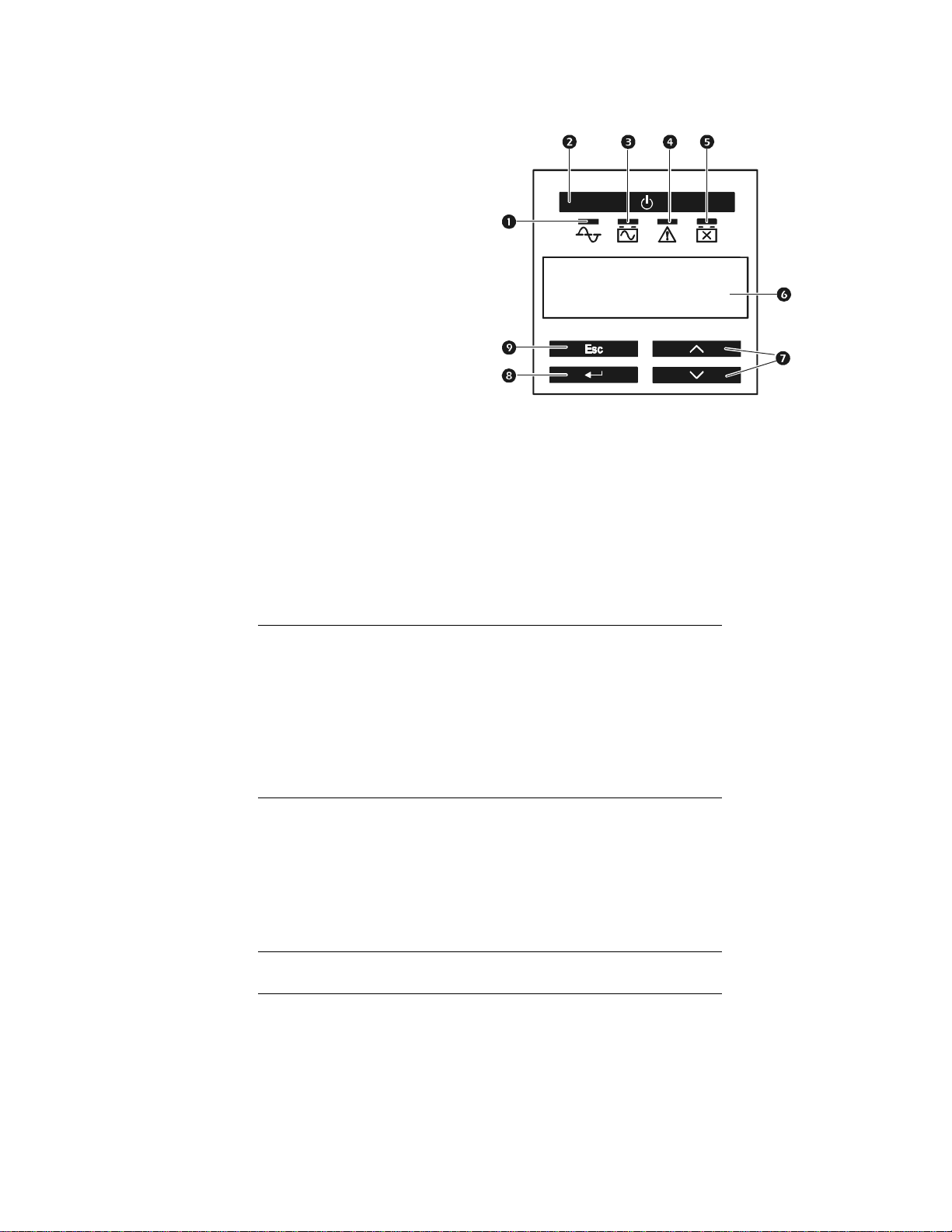
Online LED
On Battery LED
UPS Output
Fault LED
Replace Battery LED
Display screen
UP and DOWN keys
ENTER key
ESCAPE key
Using the display interface
Use the UP and DOWN keys to scroll through the main menu options. Press ENTER to view the
sub-menus under each main menu option. Press
Standard menus
ON/OFF key
APC By Schneider
ESCAPE to exit a sub-menu and return to a main menu.
The Standard menus are the most commonly used menus for the UPS.
Menu General Functions
Status View basic information about the UPS:
• Operating mo de
• Efficiency of the UPS
• Information about the load
• Battery capacity
• Estimated runtime
• Input and output voltage and frequency
• Information about the last transfer to battery power
• Self-test results
Configuration Configure the settings for the UPS:
• Language
• Local power quality: Good, Fair, Poor
• Choose Standard or Advanced menus
• UPS Test settings
• Reset to Factory Defaults
• Battery installation date
• Display: Always On, Auto Off, Auto Dim
Test & Diags Use the T est & Diags menu to have the UPS perfor m a
Self-Test, UPS Alarms Test or Calibration Test
About Display information about this unit:
• Unit model number
• Serial number
• Battery information
•Model number
•Installation date
•Suggested battery replacement date
•UPS firmware version
5Smart-UPS 750-3000 VA 100/120/208/230 Vac Rack-Mount
Page 7

Advanced menus
The Advanced menus provide additional options for the UPS and are available only if the display
interface is configured to use the Advanced menus.
Menu General Functions
Status View detailed information about the UPS:
•Energy meter
• Load current
• Status of the Switched Outlet Group
• Battery voltage
• Operation mode
• Efficiency
• SmartSlot Card (if applicable)
Configuration Configure advanced settings for the UPS:
• Main and Switched Outlet Group—delays and settings
• High and lower transfer points
• Sensitivity settings
• Date of last battery replacement
• Output voltage
• Battery settings
• Number of battery packs (not available on all models)
• Reset energy meter
• UPS test settings
• Display: Always On, Auto Off, Auto Dim
Control Control the Main and Switched Outlet Group to turn on,
turn off, shutdown, or reboot.
Test & Diags Perform UPS test and diagnostic functions such as user
interface testing, battery tests, and battery calibration.
Log View the event and error logs for information about any
changes to the UPS and any faults.
About V iew infor mat ion abou t the unit:
• Hardware version
• Software version
• NMC information (if applicable)
• SmartSlot Card information (if applicable)
Smart-UPS 750-3000 VA 100/120/208/230 Vac Ra ck-Mount6
Page 8

Configuration
UPS Settings
Start-up Settings
Configure these settings at initial start-up, using the display interface. As an alternative, configuration
™
can be performed using APC by Schneider Electric PowerChute
software.
Note: During start-up, use the display interface to configure these settings. If nothing is selected, the
unit will use the default settings.
Function Factory Default Options Description
Language English • English
•French*
•German*
• Spanish*
• Italian*
• Portuguese*
• Japanese*
Local Power
Quality
Menu Type Standard Standard or
Good • Good
•Fair
• Poor
Advanced
The language for the display interface.
*Language options will vary by model.
Select the quality of input utility power.
• If Good is selected, the unit will go on battery
power more often to provide the cleanest powe
upply to the connected equipment.
s
• If Poor is selected, the UPS will tolerate mo
f
luctuations in power and will go on battery po
less o
ften.
If unsure of the local power quality, select Good.
The Standard menus display a limited set of menus
and options. The Advanced menus include all
parameters.
r
re
wer
General Settings
Configure these settings at any time, using the display interface or PowerChute software.
Function Factory Default Options Description
High Transfer
Point
100 Vac:
108 Vac
120 Vac:
127 Vac
208 Vac:
225 Vac
230 Vac:
253 Vac
• 108 Vac
• 1 10 Vac
• 1 12 Vac
• 1 14 Vac
• 127 Vac
• 130 Vac
• 133 Vac
• 136 Vac
• 225 Vac
• 229 Vac
• 233 Vac
• 237 Vac
• 253 Vac
• 257 Vac
• 261 Vac
• 265 Vac
To avoid unnecessary battery usage, set the
transfer point higher if the utility voltage is
chronically high and the connected equipment
is known to work under this condition. The
POWER QUALITY setting will automatically
change this setting.
Note: Use the Advanced Menus to configure
this setting.
7Smart-UPS 750-3000 VA 100/120/208/230 Vac Rack-Mount
Page 9

Function Factory Default Options Description
Low Transfer
Point
Nominal Output
Voltage
Transfer
Sensitivity
100 Vac:
92 Vac
120 Vac:
106 Vac
208 Vac:
182 Vac
230 Vac:
208 Vac
100 Vac N/A Set the nominal output voltage of the UPS on
120 Vac N/A
230 Vac 208-252 Vac
High High, Reduced, Low Select the level of sensitivity to power events
•86 Vac
•88 Vac
•90 Vac
•92 Vac
•97 Vac
• 100 Vac
• 103 Vac
• 106 Vac
• 170 Vac
• 174 Vac
• 178 Vac
• 182 Vac
• 196 Vac
• 200 Vac
• 204 Vac
• 208 Vac
Set the transfer point lower if the utility
voltage is chronically low and the connected
equipment can tolerate this condition.This
setting may also be adjusted using the power
quality setting.
Note: Use the Advanced Menus to configure
this setting.
battery. This is available on 230 Vac models
only.
that the UPS will tolerate.
• High: The UPS will go on battery power
more often to provide the cleanest po
s
upply to the connected equipment.
• Low: The UPS will tolerate mo
ctuations in power and will go on battery
flu
power less often.
wer
re
If the connected load is sensitive to power
disturbances, set the sensitivity to High.
Low Battery
Warning
Date of Last
Battery
Replacement
Audible Alarm On On/Off The UPS will mute all audible alarms if this is
Battery SelfTest Interval
Setting
Reset to Factory
Default
120 sec Set the value in
seconds
Date set at factory Reset this date when the battery module is replaced.
On start-up and
every 14 days since
the last test
No Yes/No Restore the UPS factory default settings.
• Never
• Star t- up only
• Frequency of test
(every 7 to 14 days)
The UPS will emit an audible alarm when the
remaining runtime has reached this level.
set to Off or when the display keys are
pressed.
The interval at which the UPS will execute a
self-test.
Smart-UPS 750-3000 VA 100/120/208/230 Vac Ra ck-Mount8
Page 10

Main Outlet Group and Switched Outlet Group
Overview
The Main Outlet Group and the Swit ched Outl et Group can be conf ig ured to indepen dently turn of f , turn
on, shut down, and reboot connected equipment. (These features are not available on the 750 VA tower
units.)
The Main and Switched Outlet Groups can be configured to do the following:
urn off: Disconnect from power immediately and restart only with a manual command.
T
•
•
T
urn on: Connect to power immediately.
•Shutdown: Disconnect power in sequence, and automatically reapply power in sequence wh
u
tility power becomes available.
•Reboot: Shut down and restart.
In addition, the Main Outlet Group and the Switched Outlet Group can be configured to do the
following:
•Turn on or off in a specified sequence
•
Aut
omatically turn off or shut down when various conditions occur
Note: If the Main and Switched Outlet Groups are not configured, all of the outlets on the
unit will still provide battery back-up power.
Using the Main and Switched Outlet Groups
The Main Outlet Group functions as a master switch. It will turn on first when power is
applied, and shut off last when there is a power outage and battery runtime has been
exhausted.
The Main Outlet Group must be turned on for the Switched Outlet Group to turn on.
1. Connect critical equipment to the Main Outlet Group.
en
2. Connect peripheral equipment to the Switched Outlet Group.
– Nonessential equipmen t that should shut of f quickly in the event of a power outa ge to conser
ba
ttery runtime can be added to a short power off delay
– If equipment has dependent peripherals that must restart or shut down in a specif ic order, s uch
as an ethernet switch that must restart before a connected server, connect the devices to
separate groups
– Equipment that needs to reboot independently from other equipment should be added to
eparate group
s
3. Use the Configuration menus to configure how the Swit che d Out let Gro up will react in the event
of a power outage.
Customize the Main and Switched Outlet Groups
Use the Control menus to change the Main Outlet Group and the Switched Outlet Group settings.
ve
a
9Smart-UPS 750-3000 VA 100/120/208/230 Vac Rack-Mount
Page 11

Function Factory D efault Options Description
Name String
Outlet Group
UPS Name String UPS Outlets
Outlet Group 1
Edit these names using an external interface, such as the Network
Management Card Web interface.
Turn On Delay 0 sec Set the value in
seconds
Turn Off Delay • 0 sec (UPS Outlets)
• 90 sec (Switc
tlet Groups)
Ou
hed
Set the value in
seconds
Reboot Duration 8 sec Set the value in
seconds
Minimum Return
Time
Load Shed On
Battery
0 sec Set the value in
seconds
Disabled •Shutdown with
Delay
• Shutdown
immediately
• Turn off
immediately
• Turn off with delay
• Disabled
Load Shed Time
when On Battery
Load Shed On
Runtime
Disabled Set the value in
seconds
Disabled •Shutdown with
delay
• Shutdown
immediately
• Turn off
immediately
• Turn off with delay
• Disabled
Load Shed On
Runtime
Disabled Set the value in
seconds
Remaining
Load Shed on
Overload
Disabled • Disabled
•Enabled
The amount of time the UPS or
Outlet Group
will wait between receiving the
the Switched
command to turn on and the actual startup.
The amount of time that the UPS or
Outlet Group
will wait between receiving the
the Switched
command to turn off and the actual shut down.
The amount of time that the UPS or
Outlet Group
must remain off before it will
the Switched
restart.
The amount of battery runtime that must be
available before the UPS or
will turn on.
Group
the Switched Outlet
When the unit switches to battery power, the UPS
can disconnect power to the
to save runtime.
Group
Configure this delay time, use the
T
IME WHEN ON BATTERY setting.
Switched Outlet
LOAD SHED
The amount of time the outlets will function on
battery power before they will turn off.
When the battery runtime falls below the
specified value, the
Switched Outlet Group will
turn off.
Configure this time using the
R
UNTIME REMAINING setting.
LOAD SHED
When the remaining runtime reaches this level,
the
Switched Outlet Group will turn off.
In the event of an overload (greater than 100%
output), the
Switched Outlet Group will
immediately turn off to conserve power for
critical loads. The
the Switched Outlet Group will
only turn on again with a manual command.
Network Management Card Settin gs
These settings are available only on units that have a Network Management Card (NMC) and are set in the factory.
These settings can only be modified using an external interface, like the NMC web interface.
•
NMC IP Ad
•
NMC IP Ad
MC Subnet Mask
N
•
•
NMC Defau
dress Mode
dress
lt Gateway
Smart-UPS 750-3000 VA 100/120/208/230 Vac Ra ck-Mount10
Page 12
Emergency Power Off
EPO Overview
The Emergency Power Off (EPO) option is a safety feature that will immediately disconnect all
connected equipment from utility power. The UPS will immediately shut down and will not switch to
battery power.
The UPS must be manually restarte d to reapply powe r to connecte d equipment. Pr ess
panel of the unit.
ON/OFF on the front
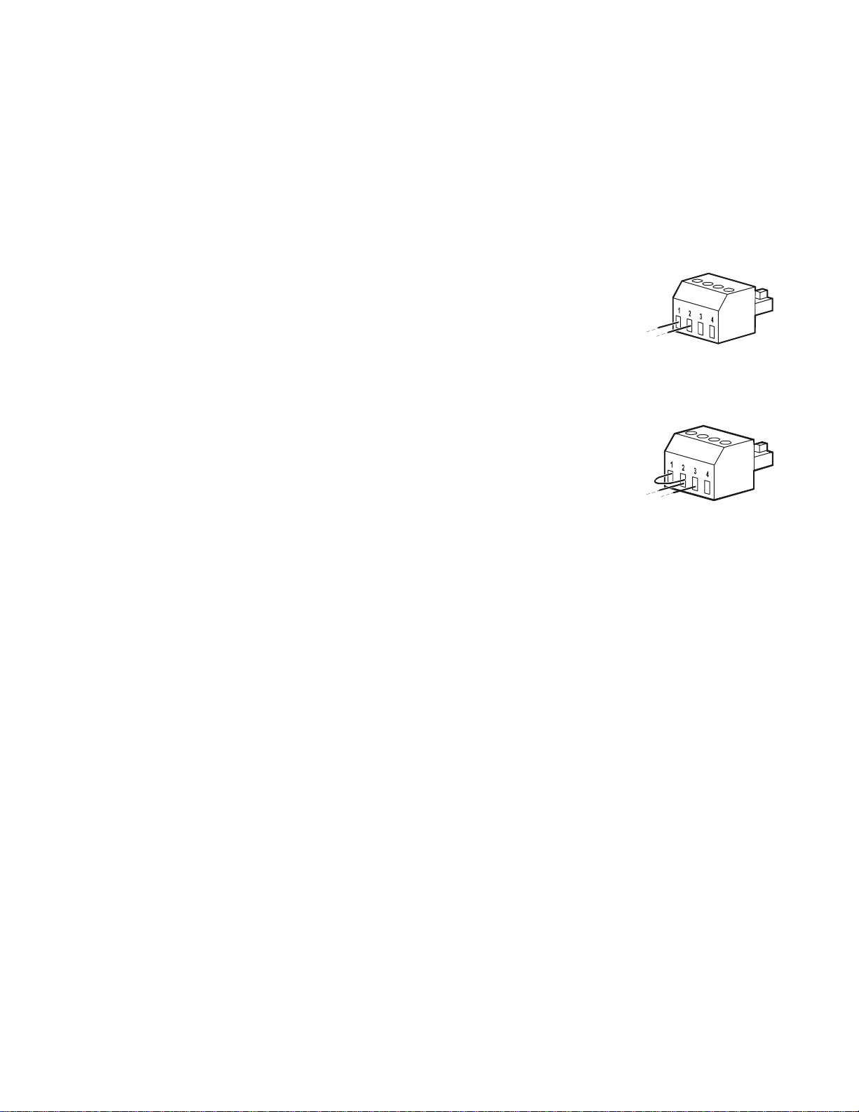
Normally open contacts
1. If the EPO switch or relay contacts are normally open, insert the wires
fr
om the switch or contacts at pins 1 and 2 of the EPO terminal bloc
Use
16-28 AWG wire
2.
Secure the wires by tightening the scre
f the contacts are closed, the UPS will turn OFF and power will be removed from the load.
I
.
ws.
k.
Normally closed contacts
1. If the EPO switch or relay contacts are normally closed, insert the wires
fr
om the switch or contacts at pins 2 and 3 of the EPO terminal bloc
Use
16-28 AWG wire
2.
Insert a wire jumper between pins 1 and 2. Secure the wires by
tightening the three screws at positions 1, 2, and 3.
If the contacts are opened, the UPS will turn OFF and power will be removed from the load.
Note: The power for opera ti ng t he EPO circuit is sourc ed f rom p in 1 . Thi s i s a n isolated 24 V which ca n
source only a few milliamperes.
.
k.
If the normally closed (NC) EPO configuration is used, the EPO switch or relay should be rated for dry
circuit applications, the rating should be for low voltage and low current applications. This normally
implies th e contacts are gold plated .
Adhere to all national and local electrical codes when wiring the EPO. Wiring must be performed
by a qualified electrician.
The EPO interface is a Safety Extra Low Voltage (SELV) circuit. Connect the EPO interface only to
other SELV circuits. The EPO interface monitors circuits that have no determined voltage potential.
SELV circuits are controlled by a switch or relay properly isolated from utility power. To avoid damage
to the UPS, do not connect the EPO interface to any circuit other than a SELV circuit.
Use one of the following cable types to connect the UPS to the EPO switch.
: Class 2 cable for general use.
CL2
•
•
CL2
P: Plenum cable for use in ducts, plenums, and other spaces used for environmental air.
•
•
•Installation in Canada: Use only CSA certified, type ELC, (extra low voltage control cable).
•Installation in countries other than Canada and the USA: Use standard low voltage cable in
R: Riser cable for use in a vertical run in a floor-to-floor shaft.
CL2
CLEX:
accordance with national and local regulations.
Limited use cable for use in dwellings and for use in raceways.
11Smart-UPS 750-3000 VA 100/120/208/230 Vac Rack-Mount
Page 13

Troubleshooting
Problem and Possible Cause Solution
The UPS will not turn on or there is no output.
The unit has not been turned on. Press the ON key once to turn on the UPS.
The UPS is not connected to utility
power.
The input circuit breaker has tripped. Reduce the load on the UPS. Disconnect nones sential equi pment and reset the
The unit shows very low or no input
utility voltage.
The battery connector plug is not
securely connected.
There is an internal UPS fault. Do not attempt to use the UPS. Unplug the UPS and have it serviced
Be sure the power cable is securely connected to the unit and to the utility
power supply.
circuit breaker.
Check the utility power supply to the UPS by plugging in a table lamp. If the
light is very dim, check the utility voltage.
Be sure that all battery connections are secure.
immediately.
The UPS is operating on battery, while connected to input utility power.
The input circuit breaker has tripped. Disconnect nonessential equipment and reset the circuit breaker.
There is very high, very low, or
distorted input line voltage.
Move the UPS to a different outlet on a dif ferent circuit. Test the input voltage
with the utility voltage display. If acceptable to the connected equipment,
reduce the UPS sensitivity.
UPS is emitting an audible beeping sound.
The UPS is operating normally. None. The UPS is protecting the connected equipment.
UPS does not provide expected backup time.
The UPS battery is weak due to a
recent power outage or is near the end
of its service life.
The UPS is experiencing an overload
condition.
Charge the battery. Batteries require recharging after extended outages and
wear out faster when put into service often or when operated at elevated
temperatures. If the battery is near the end of its service life, consider
replacing the battery even if the replace battery LED is not illuminated.
Check the UPS load display. Unplug unnecessary equipment, such as printers.
Display interface LEDs flash sequentially.
The UPS has bee n shut down rem otely
through software or an optional accessory
card.
None. The UPS will restart automatically when utility power is restored.
The Fault LED is illuminated. The UPS displays a fault message and emits a constant beeping sound.
Internal UPS fault. Do not attempt to use the UPS. Turn the UPS off and have it serviced
immediately.
All LEDs are illuminated and the UPS is plugged into a wall outlet.
The UPS has shut down and the
battery has discharged from an
extended outage.
None. The UPS will return to normal operation when the power is restored
and the battery has a sufficient charge.
Smart-UPS 750-3000 VA 100/120/208/230 Vac Ra ck-Mount12
Page 14

Problem and Possible Cause Solution
The replace battery LED is illuminated.
The battery has a weak charge. Allow the battery to rechar ge for at least four hours. Then, perform a self-test.
If the problem persists after recharging, replace the battery.
The replacement battery is not
properly connected.
Be sure the battery connector is securely connected.
The display interface has a Site Wiring Fault message.
Wiring faults detected include
missing ground, hot neutral,
polarity reversal, and overloaded
neutral circuit.
If the UPS indicates a site wiring fault, have a qualified electrician inspect the
building wiring. (Applicable for 120 V units only.)
13Smart-UPS 750-3000 VA 100/120/208/230 Vac Rack-Mount
Page 15

Transport
1. Shut down and disconnect all connected equipment.
2. Disconnect the unit from utility power.
3. Disconnect all internal and extern al batteries (if applicable).
4. Follow the shipping instructions outlined in the Service section of this manual.
Service
If the unit requires service, do not return it to the dealer. Follow these steps:
1. Review the Troubleshooting section of the manual to eliminate common problems.
2. If the problem persists, contact APC by Schneider Electric Customer Support through the APC by
Schneider Electric web site, www.apc.com.
a. Note the model number and serial number and the date of purchase. The model and serial
numbers are locate d on th e rear panel of t he unit and a re availabl e thr ough the LCD d ispla
on sel
ect models.
b. Call Customer Support and a technician will attempt to solve the pr oblem over the phone . If
this is not possible, the technician will issue a Returned Material Authorization Number
(RMA#).
y
c. If the unit is under warranty, the repairs are free
Service procedures and returns may vary internationally. Refer to the
d.
Electric
3. Pack the unit properly to avoid damage i n transit . Never use foam beads for packaging. Damage sustained
in transit is not covered under warranty.
a. Note: When shipping within the United States, or to the United States always
DISCONNECT O
Department of Transportation (DOT) and IATA r egul ations. The in ternal batteri es ma
r
b. Batteries may remain connected in the XBP during shipment. Not all units utilize XLBPs.
4. Write the RMA# provided by Customer Support on the outside of the package.
5. Return the unit by insured, prepaid carrier to the address provided by Customer Support.
web site, www.apc.com for country specific instructions.
NE UPS BATTERY before shipping in compliance with U.S.
emain in the UPS.
.
APC by Schneider
y
Smart-UPS 750-3000 VA 100/120/208/230 Vac Ra ck-Mount14
Page 16

LIMITED FACTORY WARRANTY
Schneider Electric IT Corporation (SEIT), warrants its products to be free from defects in materials and workmanship for a
period of two (2) years from the date of purchase. The SEIT obligation under this warranty is limited to repairing or replacing, at
its own sole option, any such defective products. Repair or replacement of a defective product or parts thereof does not extend
the original warranty period.
This warranty applies only to the original purchaser who must have properly registered the product within 10 days of purchase.
Products may be registered online at warranty.apc.com.
SEIT shall not be liable under the warran ty if it s t esting and e xam in at ion disclo se tha t the alle ge d defect in th e prod uc t d oes not
exist or was caused by end user or any third per s on misuse, negligence, improper installa tion, testing, operation or use of the
product contrary to SEIT recommendations or specifications. Further, SEIT shall not be liable for defects resulting from: 1)
unauthorized attempts to repair or modify the product, 2) incorrect or inadequate electrical voltage or connection, 3)
inappropriate on site operation conditions, 4) Acts of God, 5) exp osu re to the eleme nts, or 6) thef t. In no even t shall SEIT have
any liability und er this warranty for any pr oduct where the serial nu mber has been altered, def aced, or removed.
EXCEPT AS SET FORTH ABOVE, THERE ARE NO WARRANTIES, EXPRESS OR IMPLIED, BY OPERATION OF LAW
OR OTHERWISE, APPLICABLE TO PRODUCTS SOLD, SERVICED OR FURNISHED UNDER THIS AGREEMENT OR
IN CONNECTION HEREWITH.
SEIT DISCLAIMS ALL IMPLIED WARRANTIES OF MERCHANTABILITY, SATISFACTION AND FITNESS FOR A
PAR TICULAR PURPOSE.
SEIT EXPRESS WARRANTIES WILL NOT BE ENLARGED, DIMINISHED, OR AFFECTED BY AND NO OBLIGATION
OR LIABILITY WILL ARISE OUT OF, SEIT RENDERING OF TECHNICAL OR OTHER ADVICE OR SERVICE IN
CONNECTION WITH THE PRODUCTS.
THE FOREGOING WARRANTIES AND REMEDIES ARE EXCLUSIVE AND IN LIEU OF ALL OTHER WARRANTIES
AND REMEDIES. THE WARRANTIES SET FORTH ABOVE CONSTITUTE SEIT SOLE LIABILITY AND PURCHAS ER
EXCLUSIVE REMEDY FOR ANY BREACH OF SUCH WARRANTIES. SEIT WARRANTIES EXTEND ONLY TO
ORIGINAL PURCHASER AND ARE NOT EXTENDED TO ANY THIRD PARTIES.
IN NO EVENT SHALL SEIT, ITS OFFICERS, DIRECTORS, AFFILIATES OR EMPLOYEES BE LIABLE FOR ANY
FORM OF INDIRECT, SPECIAL, CONSEQUENTIAL OR PUNITIVE DAMAGES, ARISING OUT OF THE USE,
SERVICE OR INSTALLATION OF THE PRODUCTS, WHETHER SUCH DAMAGES ARISE IN CONTRACT OR TORT,
IRRESPECTIVE OF FAULT, NEGLIGENCE OR STRICT LIABILITY OR WHETHER SEIT HAS BEEN ADVISED IN
ADVANCE OF THE POSSIBILITY OF SUCH DAMAGES. SPECIFICALLY, SEIT IS NOT LIABLE FOR ANY COSTS,
SUCH AS LOST PROFITS OR REVENUE, WHETHER DIRECT OR INDIRECT, LOSS OF EQUIPMENT, LOSS OF USE
OF EQUIPMENT , LOSS OF SOFTWARE, LOSS OF DA TA, COSTS OF SUBSTITUANTS, CLAIMS BY THIRD PARTIES,
OR OTHERWISE.
NOTHING IN THIS LIMITED WARRANTY SHALL SEEK TO EXCLUDE OR LIMIT SEIT LIABILITY FOR DEATH OR
PERSONAL INJURY RESULTING FROM ITS NEGLIGENCE OR ITS FRAUDULENT MISREPRESENTATION OF TO
THE EXTENT THAT IT CANNOT BE EXCLUDED OR LIMITED BY APPLICABLE LAW.
To obtain service under warranty you must obtain a Returned Material Authorization (RMA) number from customer support.
Customers with warranty claims issues may access the SEIT worldwide customer support network th rough the APC web site:
www.apc.com. Select your country from the country selection drop down menu. Open the Support tab at the top of the web page
to obtain information for customer support in your region. Pr oducts must be retu rned with transportation charges prepaid an d
must be accompanied by a brie f description of the problem encountered and proof of date and place of purchase.
15Smart-UPS 750-3000 VA 100/120/208/230 Vac Rack-Mount
Page 17

Select models are ENERGY STAR® qualified.
© 2014 APC by Schneider Electric. APC, the APC logo and APC, the APC logo, PowerChute and Smart-UPS
and PowerChute are owned by Schneider Electric Industries S.A.S., or their affiliated companies. All other
trademarks are property of their respective owners.
10/2014EN 990-3858C
 Loading...