

Page 1
Application
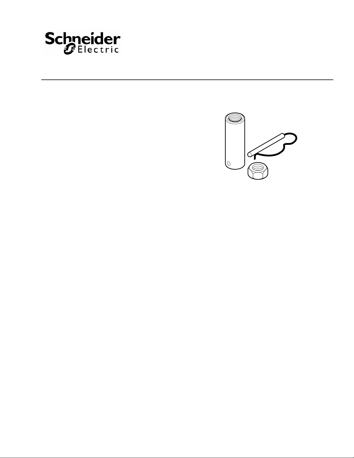
The AV-401 valve linkage kit is used to field assemble
MK-4600 series pneumatic actuators to a variety of
1/2" through 2" valve bodies.
Features
• Kit fits both current and obsolete TAC
Barber-Colman valve bodies
AV-401
Pneumatic Actuator Valve Linkage Kit
General Instructions
Applicable Literature
• Environmental Controls Cross-Reference Guide,
F-23638
• Environmental Controls Reference Manual, F-21683
• Environmental Controls Application Manual,
F-21335
• Pneumatic Products Catalog, F-27383
• MK-4600 Series, Pneumatic Valve Actuator General
Instructions, F-13894
• Environmental Controls Valve Selection Guide,
F-26094
• EN-205 Water System Guidelines, F-26080
Printed in U.S.A. 6-10 Copyright 2010 Schneider Electric All Rights Reserved. F-25586-5
Page 2

SPECIFICATIONS
Refer to Table-1 to select compatible valves and actuators for use with the AV-401 linkage
kit. Refer to Tab le - 3 and Ta bl e - 3 for a listing of the combinations of obsolete valve bodies and
actuators used with the AV-401 linkage kit.
Table-1 VB-7XXX Series Valve and Actuator Selections for Use With AV-401 Linkage.
Valve
Assembly
Number †
VK-7211-301
VK-7211-303
VK-7211-301
VK-7211-302
VK-7211-303
VK-7212-301
VK-7212-302
VK-7212-303
No factory
assembly
available ‡
VK-7214-301
VK-7214-302
VK-7214-303
VK-7221-301
VK-7221-302
VK-7221-303
VK-7222-301
VK-7222-302
VK-7222-303
VK-7223-301
VK-7223-302
VK-7223-303
Actuator
Number
MK-4601
MK-4621
MK-4601
MK-4611
MK-4621
MK-4601
MK-4611
MK-4621
MK-4601
MK-4611
MK-4621
MK-4601
MK-4611
MK-4621
MK-4601
MK-4611
MK-4621
MK-4601
MK-4611
MK-4621
MK-4601
MK-4611
MK-4621
Spring
Range
3-6
10-13
3-6
5-10
10-13
3-6
5-10
10-13
3-6
5-10
10-13
3-6
5-10
10-13
3-6
5-10
10-13
3-6
5-10
10-13
3-6
5-10
10-13
Valve Body Number
Standard, No Linkage
Angle Straightway 3-Way
VB-7211-0-3-XX —
VB-7211-0-4-XX
VB-7212-0-4-XX
VB-7213-0-4-XX
VB-7214-0-4-XX
VB-7221-0-4-XX
VB-7222-0-4-XX
VB-7223-0-4-XX
Set Stem
Height
(Dim. “X”)
in. (mm)
1-1/32
(26)
Stem Down
—
1-3/8
(35)
Stem Up
MK-4601
MK-4611
MK-4621
MK-4601
MK-4611
MK-4621
No factory
assembly
available ‡
VK-7312-301
VK-7312-302
VK-7312-303
VK-7313-301
VK-7313-302
VK-7313-303
No factory
assembly
available ‡
VK-7332-303
VK-7332-313
†VK4-7XXX-0-4-XX; indicates valve assembly with positive positioner.
‡Purchase actuator, linkage, and valve body separately.
MK-4601
MK-4611
MK-4621
MK-4601
MK-4611
MK-4621
MK-4601
MK-4611
MK-4621
MK-4601
MK-4611
MK-4621
MK-4601
MK-4611
MK-4621
MK-4601
MK-4611
MK-4621
MK-4601
MK-4611
MK-4621
MK-4621
MK-4621-422
3-6
5-10
10-13
3-6
5-10
10-13
3-6
5-10
10-13
3-6
5-10
10-13
3-6
5-10
10-13
3-6
5-10
10-13
3-6
5-10
10-13
3-6
5-10
10-13
3-6
5-10
10-13
10-13
10-11 1/4
VB-7224-0-4-XX
—
VB-7253-0-4-XX
VB-7263-0-4-XX
VB-7273-0-4-XX
VB-7283-0-4-XX
—
VB-7312-0-4-XX
VB-7313-0-4-XX
VB-7323-0-4-XX
VB-7314-0-4-XX
VB-7332-0-4-XX
1-1/32
(26)
Stem Down
1-3/8
(35)
Stem Up
1-1/32
(26)
Stem Down
1-3/8
(35)
Stem Up
1-15/32
(36)
Stem Up
1-1/4
(32)
Stem Down
2 Copyright 2010 Schneider Electric All Rights Reserved. F-25586-5
Page 3

Table-2 Obsolete VB-9XXX Valve Bodies Using AV-401 Linkage Kit.
Valve
Assembly
Number †
VK-1115-401
VK-1115-421
VK-9211-301
VK-9211-302
VK-9211-303
VK-9212-301
VK-9212-302
VK-9212-303
VK-9213-301
VK-9213-302
VK-9213-303
VK-9214-301
VK-9214-302
VK-9214-303
VK-9221-301
VK-9221-302
VK-9221-303
VK-9222-301
VK-9222-302
VK-9222-303
VK-9223-301
VK-9223-302
VK-9223-303
VK-9224-301
VK-9224-302
VK-9224-303
VK-9253-301
VK-9253-302
VK-9253-303
VK-9263-301
VK-9263-302
VK-9263-303
VK-9273-301
VK-9273-302
VK-9273-303
Actuator
Number
MK-4601
MK-4621
MK-4601
MK-4611
MK-4621
MK-4601
MK-4611
MK-4621
MK-4601
MK-4611
MK-4621
MK-4601
MK-4611
MK-4621
MK-4601
MK-4611
MK-4621
MK-4601
MK-4611
MK-4621
MK-4601
MK-4611
MK-4621
MK-4601
MK-4611
MK-4621
MK-4601
MK-4611
MK-4621
MK-4601
MK-4611
MK-4621
MK-4601
MK-4611
MK-4621
Spring
Range
3-6
10-13
3-6
5-10
10-13
3-6
5-10
10-13
3-6
5-10
10-13
3-6
5-10
10-13
3-6
5-10
10-13
3-6
5-10
10-13
3-6
5-10
10-13
3-6
5-10
10-13
3-6
5-10
10-13
3-6
5-10
10-13
3-6
5-10
10-13
Valve Body Number
Standard, No Linkage
Angle Straightway 3-Way
VB-111-0-3-XX —
VB-9211-0-4-XX
VB-9212-0-4-XX
VB-9213-0-4-XX
VB-9214-0-4-XX
VB-9221-0-4-XX
VB-9222-0-4-XX
VB-9223-0-4-XX
VB-9224-0-4-XX
—
VB-9253-0-4-XX
VB-9263-0-4-XX
VB-9273-0-4-XX
Stem
Height
in. (mm)
1-1/32
(26)
Stem Down
—
1-3/8
(35)
Stem Up
1-1/32
(26)
Stem Down
1-3/8
(35)
Stem Up
1-1/32
(26)
Stem Down
VK-9283-301
VK-9283-302
VK-9283-303
VK-9312-301
VK-9312-302
VK-9312-303
VK-9313-301
VK-9313-302
VK-9313-303
VK-9314-301
VK-9314-302
VK-9314-303
VK-9332-303
VK-9332-313
†VK4-7XXX-0-4-XX; indicates valve assembly with positive positioner.
MK-4601
MK-4611
MK-4621
MK-4601
MK-4611
MK-4621
MK-4601
MK-4611
MK-4621
MK-4601
MK-4611
MK-4621
MK-4621
MK-4621-422
3-6
5-10
10-13
3-6
5-10
10-13
3-6
5-10
10-13
3-6
5-10
10-13
10-13
10-11 1/4
VB-9283-0-4-XX
—
VB-9312-0-4-XX
VB-9313-0-4-XX
VB-9314-0-4-XX
VB-9332-0-4-XX
1-3/8
(35)
Stem Up
1-1/4
(32)
Stem Down
F-25586-5 Copyright 2010 Schneider Electric All Rights Reserved. 3
Page 4
C A U T I O N
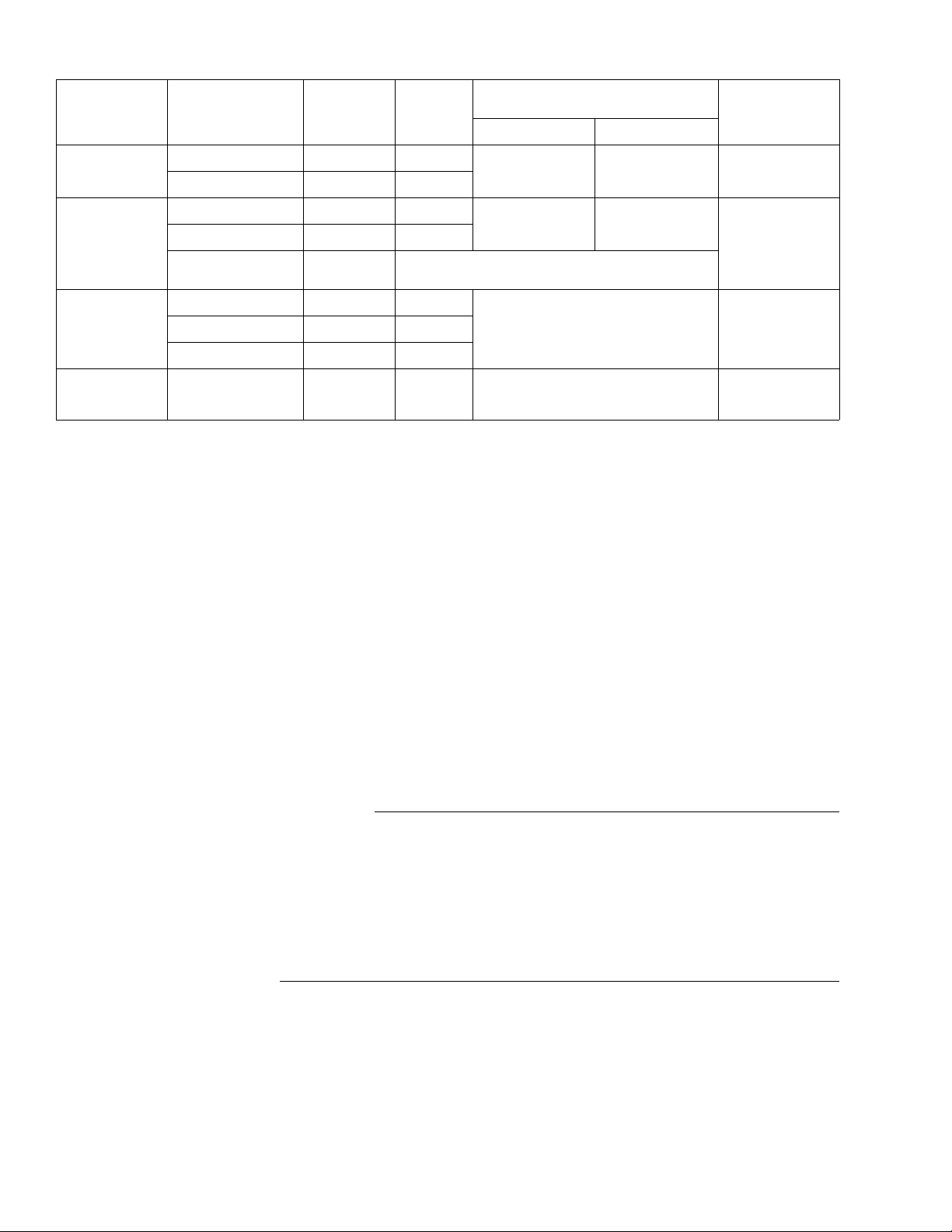
Table-3 Obsolete Valve Bodies Using AV-401 Linkage Kit.
Valve
Type
Radiator
(Union End)
Globe
Screwed
N.C.
Globe
Screwed
3-Way
Sequencing
Flared
3-Way
†No longer available - see the Maintenance Parts Catalog, F-26033 for available maintenance and repair parts.
Valve
Assembly
Number †
VK-1115-401-4 MK-4601 3-6
VK-1115-421-4 MK-4621 10-13
VK-1515-401 MK-4601 3-6
VK-1515-421 MK-4621 10-13
VK-2455
Obsolete
VK-3145-401 MK-4601 3-7
VK-3145-411 MK-4611 5-10
VK-3145-421 MK-4621 8-13
VK-3345-411 MK-4611 5-10 VB-334-0-5-4
Actuator
Number
MK-4600 Replace with VK-9223 Series
Spring
Range
Valve Body Number
Standard, No Linkage
Angle Straightway
_ _ VB-111-0-4-X
_ _ VB-151-0-1-X
VB-314-0-1-X
Required Components
Selecting the valve assembly number from Table-1 specifies a complete assembly of an
actuator, valve body, and the AV-401 linkage kit. If no valve assembly number is available the
actuator, valve body, and AV-401 listed in
Ta bl e -1 must be purchased separately.
Stem Height
Setting for AV-401
(Dim. “X”)
in. (mm)
1-1/16 (27)
Stem Down
1-13/32 (36)
Stem Up
1-1/16 (27)
Stem Down
1-1/4 (32)
Stem Down
INSTALLATION
Inspection
Requirements
Mounting
Inspect the package for damage. If damaged, notify the appropriate carrier immediately. If
undamaged, open the package and inspect the device for obvious damage. Return any
damaged products.
• Tools (not provided):
Appropriate hand tools for field service.
• Training:
Installer must be a qualified, experienced technician
• Avoid locations where excessive moisture, corrosive fumes, or vibration are present. Do
not insulate above actuator mounting nut trapping moisture.
• Install all two-way valves so that they close against the flow. An arrow on the valve body or
a tag indicates the proper flow direction.
• Install all three-way mixing valves with two inlets and one outlet.
• Install all three-way diverting valves with one inlet and two outlets.
• Do not install the actuator below the center line of the valve. For steam applications only,
mount the actuator above the valve body at 45° from vertical.
1. Actuators can be mounted in any upright position above the centerline of a valve body.
2. When selecting a location, allow sufficient room for accessories and for service of the product.
3. Maintain proper flow direction when installing all globe and radiator-type valves. Flow direction is indicated by an arrow on the valve body or by information on the attached tag.
4 Copyright 2010 Schneider Electric All Rights Reserved. F-25586-5
Page 5
ASSEMBLY PROCEDURE
N O T E
X
Top Surface of
Packing Nut
Center of Hole in
Stem Extension
Locknut
Stem Extension
Packing Nut
Valve
Mounting Nut
For current valves refer to Table-1 to maintain the proper stem height during assembly.
For obsolete valves see Ta bl e - 1 or Ta b l e- 3 .
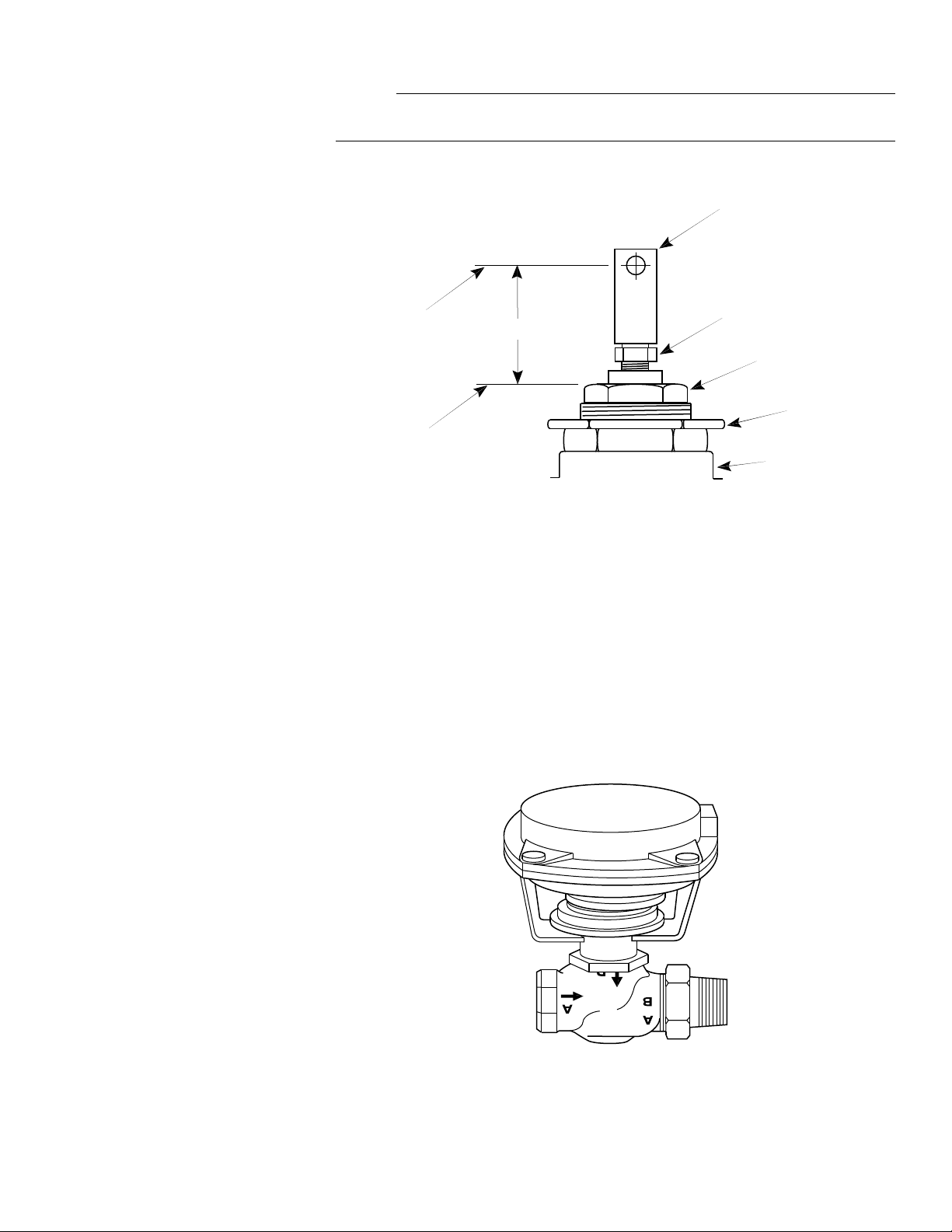
1. Thread the locknut and the stem extension several turns onto the valve stem (Figure-1).
Figure-1 Assembly of AV-401 Linkage Kit onto Valve.
2. Push or pull the valve stem to the position (stem up or stem down) noted in Ta bl e -1 ,Ta b le - 1, or Ta b le -3 .
3. Adjust the height of the stem extension as indicated in Ta b le - 1 . This height (dimension
“X”) is measured from the top surface of the packing nut to the center of the hole in the
stem extension (
Figure-1).
4. Holding the stem extension stationary, tighten the locknut against it to secure it in position on the stem.
5. Install the actuator onto the valve by screwing the actuator base onto the mounting nut
Figure-2). The actuator may be rotated as desired to facilitate making the pneumatic
(
connection.
6. Apply air pressure to the actuator so that the holes in the stem extension and the actuator stem are aligned. Insert the connecting pin into the aligned holes.
F-25586-5 Copyright 2010 Schneider Electric All Rights Reserved. 5
Figure-2 MK4600 Actuator Mounted on Valve.
Page 6
MAINTENANCE
2
3
1
FIELD REPAIR
The actuator linkage requires no maintenance.
Regular maintenance of the total system is recommended to assure sustained, optimum
performance. Hard water leaves abrasive deposits and reduces component life. To maximize
valve life consult EN-205, Water System Guidelines, F-26080.
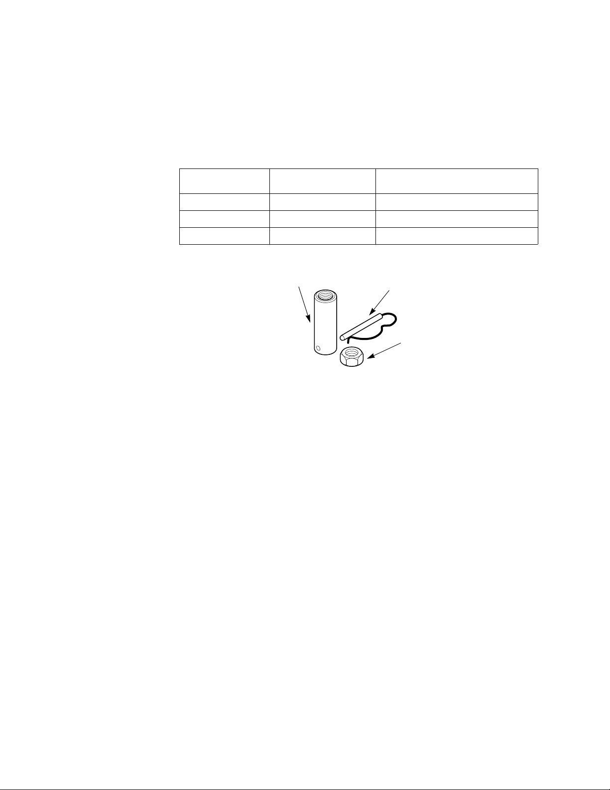
Individual parts of the actuator linkage are not repairable. Replace an inoperative actuator
linkage with a functional unit, or replace individual parts as necessary (Figure-3).
Table-4 AV-401 Replacement Parts.
Item
(See Figure-3)
1 YBA-539-1 Stem Extension
2 BDHE-136 Valve Connecting Pin
3 YBA-519 Locknut
Part No. Description
Figure-3 AV-401 Pneumatic Actuator Valve Linkage Kit.
6 Copyright 2010 Schneider Electric All Rights Reserved. F-25586-5
Page 7

F-25586-5 Copyright 2010 Schneider Electric All Rights Reserved. 7
Page 8

On October 1st, 2009, TAC became the Buildings business of its parent company Schneider Electric. This document reflects the visual identity of Schneider Electric,
however there remains references to TAC as a corporate brand in the body copy. As each document is updated, the body copy will be changed to reflect appropriate
corporate brand changes.
Copyright 2010, Schneider Electric
All brand names, trademarks and registered
trademarks are the property of their respective
owners. Information contained within this
document is subject to change without notice.
F-25586-5
 Loading...