

Schneider Electric ATV930D55N4C, ATV930D75S6, ATV950D30N4EU, ATV950D37N4EU, ATV950D37N4U Quick Start Guide
Page 1
NHA6157801
Getting Started
ENGLISH
2
6W1338000672
Altivar 930
ATV930U55N4
5,5kW - 7,5 HP
With Altivar Process ATV900
1
Download The Manuals
You must have detailed information to be able to carry out the installation and commissioning.
This information can be found in the following manuals that can be downloaded on www.schneider-electric.com/drives:
- The Altivar Process ATV900 Installation manual (NHA80932)
- The Altivar Process ATV900 Programming manual (NHA80757)
DANGER
HAZARD OF ELECTRIC SHOCK, EXPLOSION OR ARC FLASH
• Only appropriately trained persons who are familiar with and understand the contents of this manual and all other pertinent product
documentation and who have received safety training to recognize and avoid hazards involved are authorized to work on and with this drive
system. Installation, adjustment, repair and maintenance must be performed by qualified personnel.
• The system integrator is responsible for compliance with all local and national electrical code requirements as well as all other applicable
regulations with respect to grounding of all equipment.
• Many components of the product, including the printed circuit boards, operate with mains voltage.
• Only use properly rated, electrically insulated tools and measuring equipment.
• Do not touch unshielded components or terminals with voltage present.
• Motors can generate voltage when the shaft is rotated. Prior to performing any type of work on the drive system, block the motor shaft to
prevent rotation.
• AC voltage can couple voltage to unused conductors in the motor cable. Insulate both ends of unused conductors of the motor cable.
• Do not short across the DC bus terminals or the DC bus capacitors or the braking resistor terminals.
• Before performing work on the drive system:
- Disconnect all power, including external control power that may be present. Take into account that the circuit breaker or main switch
does not de-energize all circuits.
-Place a Do Not Turn On label on all power switches related to the drive system.
- Lock all power switches in the open position.
- Wait 15 minutes to allow the DC bus capacitors to discharge.
- Follow the instructions given in the chapter "Verifying the Absence of Voltage" in the installation manual of the product.
• Before applying voltage to the drive system:
- Verify that the work has been completed and that the entire installation cannot cause hazards.
- If the mains input terminals and the motor output terminals have been grounded and short-circuited, remove the ground and the
short circuits on the mains input terminals and the motor output terminals.
- Verify proper grounding of all equipment.
- Verify that all protective equipment such as covers, doors, grids is installed and/or closed.
Failure to follow these instructions will result in death or serious injury.
Electrical equipment should be installed, operated, serviced, and maintained only by qualified personnel. No responsibility is assumed by
Schneider Electric for any consequences arising out of the use of this product.
Verify The Delivery Of The Drive
• Unpack the drive and verify that it has not been damaged.
WARNING
DAMAGED DRIVE EQUIPMENT
Do not operate or install any drive or drive accessory that appears damaged.
Failure to follow these instructions can result in death, serious injury, or equipment damage.
• Verify that the drive catalog number printed on the label is the same as that on the delivery note corresponding to the purchase order.
• Write the drive Model catalog number: _____________ ___________and Serial Number: ____________________________
www.schneider-electric.com 1/4 NHA61578 - 11/2017
Page 2
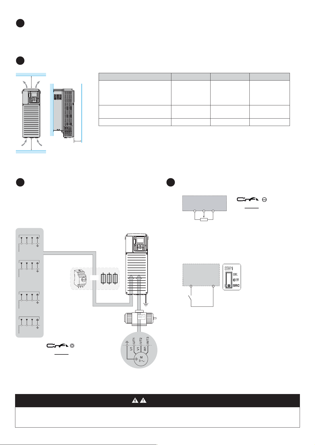
Verify The Supply Mains Compatibility
3
X1
(1)
X3
(1)
X2
(1)
For a surrounding air temperature up to 50 °C (122 °F). For other thermal conditions, see
Installation manual (NHA80932) on www.schneider-electric.com
Drive X1 X2 X3
ATV930U07
pp...ATV930D90N4,
ATV930U22S6X...ATV930D15S6X,
ATV930
pppS6, ATV930pppY6,
ATV950
pppppp
u
100 mm (3.9 in.) u 100 mm (3.9 in.) u 10 mm (0.39 in.)
ATV930D55M3...ATV930D75M3,
ATV930C11N4...ATV930C16N4
u 250 mm (10 in.) u 250 mm (10 in.) u 100 mm (3.9 in.)
ATV930C22N4
pp...ATV930C31N4pp u 200 mm (8 in.) u 150 mm (5.9 in.) u 10 mm (0.39 in.)
(1)Minimum value corresponding to thermal constraints
5
3 a 380/480 V
3 a 200/240 V
R/L1
S/L2
T/L3
R/L1
S/L2
T/L3
3 a 600 V
R/L1
S/L2
T/L3
3 a 500/690 V
R/L1
S/L2
T/L3
ATVpppppppp
M3 = 200/240 V
3-phase
ATV
pppppppp
N4 = 380/480 V
3-phase
or
See installation manual (NHA80932)
on www.schneider-electric.com
or the drive nameplate for tightening torques.
6
0,5 N.m
4.4 lb.in
• Verify that the supply mains is compatible with the drive.
3-phase supply mains _______ Volts Drive mains voltage _______ Volts
Drive range: ATV
4
Mount The Drive Vertically
pppppp M3 = 200/240 V – ATVpppppp N4 = 380/480 V – ATVpppppp S6p = 600 V – ATVpppppp Y6 = 500/690 V
Connect The Drive: Power
• Connect the drive to ground.
• Verify circuit breaker rating or fuse rating, see SCCR annex (NHA61584).
• Verify that the nominal motor voltage is compatible with the drive voltage.
Nominal motor voltage ______volts.
• Connect the drive to the motor.
• Connect the drive to the mains.
ATVpppppppp
S6p = 600 V
3-phase
ATV
pppppppp
Y6 = 500/690 V
3-phase
Connect The Drive: Control
• Connect the reference frequency AI1:
10V
AI1
COM
1...10 kΩ
• Connect the command DI1:
Control command 2-wire (factory setting)
DI1: forward
ATV pppppppp
DI1
24V
HAZARD OF FIRE OR ELECTRIC SHOCK
Wire cross sections and tightening torques must comply with the specifications provided in the installation manual.
Failure to follow these instructions will result in death or serious injury.
www.schneider-electric.com 2/4 NHA61578 - 11/2017
.... N.m
.... lb.in
DANGER
Page 3
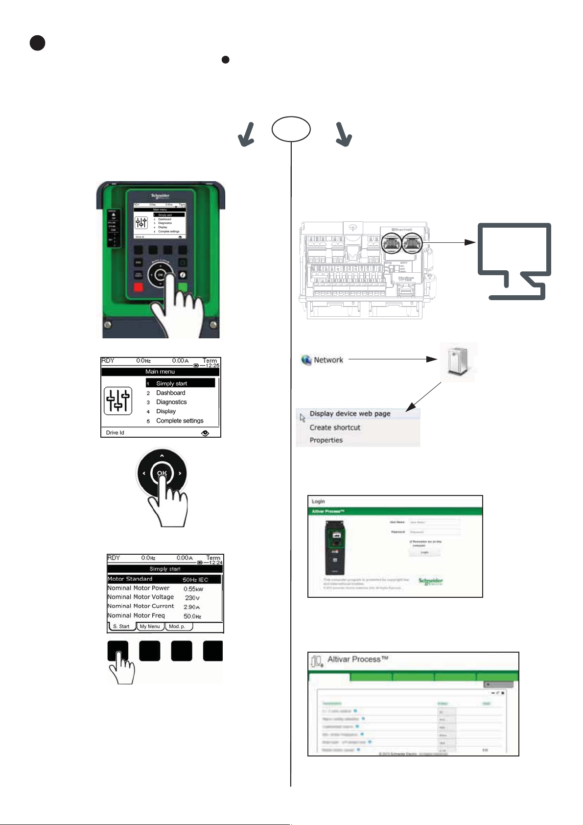
[Simply Start]
7
6
Steps to follow to access [Simply start]
1/ Connect the drive to your PC with an Ethernet cable
2/ Open Network Explorer on your PC.
Your drive appears automatically.
Right-click and select «Display
device web page» to open
Webserver.
Select [S. Start] tab.
3/ On first connection, default connection IDs are:
- User Name = ADMIN
- Password, available from the Graphic Display Terminal:
[Main Menu]
V [My preference] V [Webserver]
4/ Change default connection ID (User Name and Password).
5/ Access to [Simply Start]
Select Home tab.
Home Monitoring Diagnostic Drive Setup
Simply Start
ATV9ppppppp-MMMM
MMMM: two last
bytes of the mac
• Verify that digital input is not active (DI1, see step drawing).
• Apply power to the drive.
• If requested, set the date, time, and language.
Access to [Simply Start] by:
Graphic Display Terminal Webserver Embedded
OR
www.schneider-electric.com 3/4 NHA61578 - 11/2017
Page 4
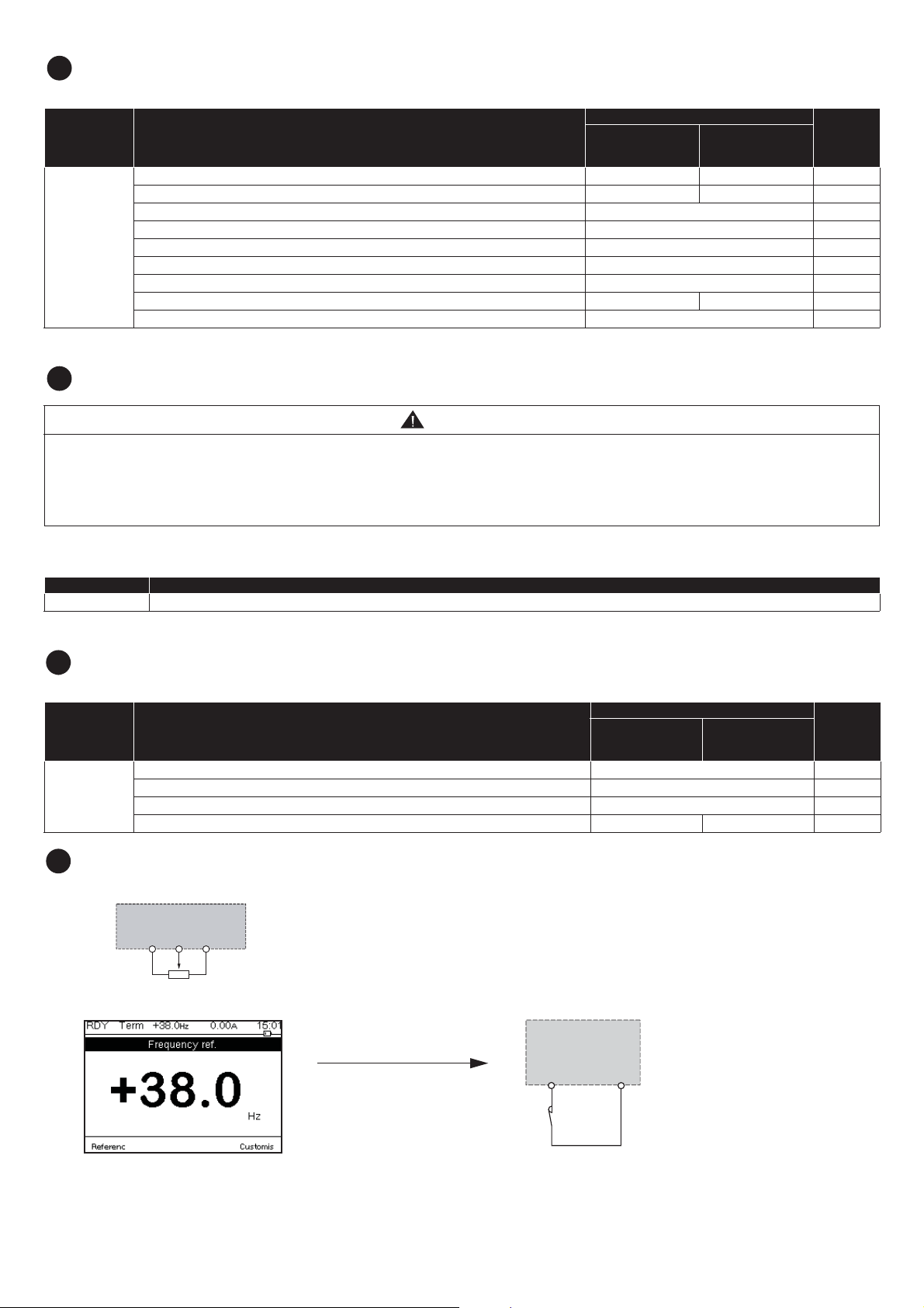
Set Motor Parameters For Asynchronous Motor
8
10
11
10V
AI1
1...10 kΩ
COM
See the motor nameplate to set the following
Menu Parameter
[Motor Standard] bFr: Standard motor frequency [50 Hz IEC] 50 (Hz) [60 Hz IEC] 60 (Hz)
[Nominal Motor Power] nPr: Nominal motor power on motor nameplate drive rating (kW) drive rating (HP)
[Nom Motor Voltage] UnS: Nominal motor voltage on motor nameplate drive rating (Vac)
[Nom Motor Current] nCr: Nominal motor current on motor nameplate drive rating (A)
[Simply start]
9
Perform A Motor [Autotuning]
[Nominal Motor Freq] FrS: Nominal motor frequency on motor nameplate 50 (Hz)
[Nominal Motor Speed] nSP: Nominal motor speed on motor nameplate drive rating (rpm)
[2/3-Wire Control] tCC: Command control by 2 wire or 3 wire control 2C
[Max Frequency] tFr: Maximum motor frequency 60 (Hz) 72 (Hz)
[Motor Th current]ItH: Motor thermal current on motor nameplate drive rating (A)
WARNING
UNEXPECTED MOVEMENT
Autotuning moves the motor in order to tune the control loops.
• Only start the system if there are no persons or obstructions in the zone of operation.
Failure to follow these instructions can result in death, serious injury, or equipment damage.
ATVpppppp M3
pppppp N4
ATV
ATV
pppppp Y6
Factory Setting
ATVpppppp S6p
Customer
Setting
During [Autotuning], the motor makes small movement. Noise development and oscillations of the system are normal.
Menu Parameter
[Simply start] [Autotuning] tUn: Set parameter to [Apply Autotuning] YES. [Autotuning] tUn is done immediately.
9
Set Basic Parameters
Factory Setting
Menu Parameter
[Acceleration ] ACC: Acceleration time 3.0 (s)
[Simply start]
[Deceleration] dEC: Deceleration time 3.0 (s)
[Low speed] LSP: Motor frequency at minimum reference 0 (Hz)
[High speed] HSP: Motor frequency at maximum reference 50 (Hz) 60 (Hz)
ATVpppppp M3
pppppp N4
ATV
pppppp Y6
ATV
ATVpppppp S6p
Start The Motor
Set the [Reference frequency] with the potentiometer
Customer
Setting
ATV pppppppp
DI1
DI1: Forward
www.schneider-electric.com 4/4 NHA61578 - 11/2017
24V
 Loading...