

Page 1
Altivar 61/71
Migration from ATV78 -> ATV61/71
Migration Manual
12/2009
AAV50749
www.schneider-electric.com
Page 2

This manual is intended to guide you through the process of replacing an Altivar 78 drive with an Altivar 61 or Altivar 71
drive.
Scope of application:
Constant torque applications:
- Replacing an Altivar 78 across the range: 525 V 690 V three-phase up to 630 kW
Variable torque applications:
- Replacing an Altivar 78 across the range: 525 V 690 V three-phase up to 800 kW
Using this manual you will be able to select the most appropriate Altivar 61 or Altivar 71 drive for your application, as well
as various options and accessories, based on the existing hardware configuration used on your Altivar 78.
You will notice that Altivar 61 and Altivar 71 drives integrate additional functionalities in terms of number of I/O and
application functions.
This manual also contains practical mounting, installation, and wiring recommendations.
To obtain maximum benefit from your Altivar 61 or Altivar 71 drive, you will need to
refer to the Installation and Programming manuals supplied with each drive.
Page 3

Contents
Determining catalog numbers____________________________________________________________________________________ 5
Choice of Altivar 61 or Altivar 71 ___________________________________________________________________________ 5
Selecting the power circuit options _________________________________________________________________________ 8
Mounting accessories ___________________________________________________________________________________ 8
Control circuit option: Remote display terminal ________________________________________________________________ 9
Choice of I/O extension cards ____________________________________________________________________________ 10
Drive setup _________________________________________________________________________________________________ 11
Mounting: Standard torque applications ____________________________________________________________________ 11
Comparison of dimensions ______________________________________________________________________________ 12
Remote display terminal ________________________________________________________________________________ 18
Power section wiring ___________________________________________________________________________________ 19
AAV50749 12/2009 3
Page 4
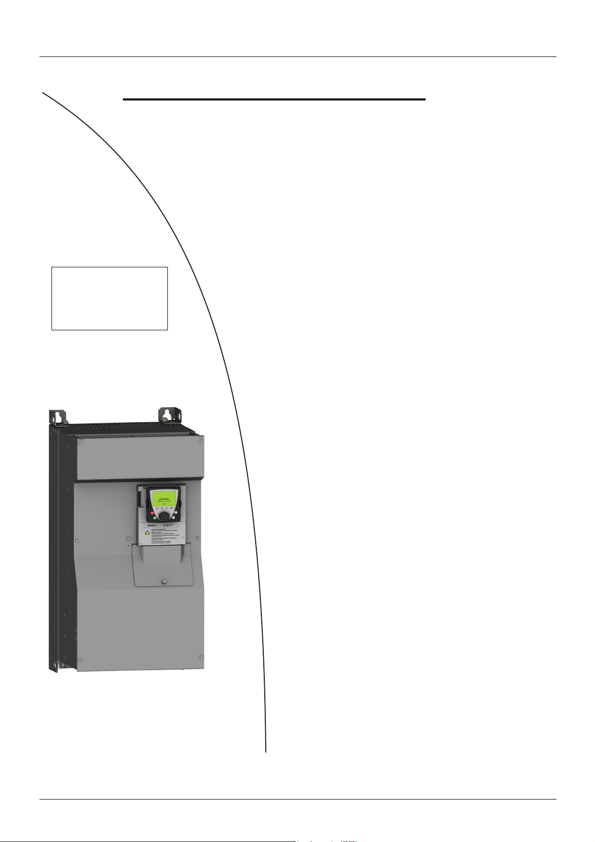
Setup procedure
b 1 Identifying the existing ATV 78
v Make an inventory of your Altivar 78 installation
Steps 3 and 4
must be
performed with
the power off
b 2 Selecting the ATV 61 or ATV 71
v Determine the Altivar 61 or Altivar 71 catalog number
v Choose the various options required
b 3 Mounting
v Mount the drive in accordance with the
instructions in this document
v Install any internal and external options
b 4 Wiring
v Connect the motor, ensuring that its
connections correspond to the voltage
v Connect the control section
v Connect the speed reference
v Connect the line supply, after making sure
that the power is off
Migrating from ATV 78 ATV 61/71
b 5 Configuration
v Drive
V
4 AAV50749 11/2009
Page 5
Determining catalog numbers
Motor power
according to
supply voltage
ATV78.(F)
catalog
number
Line choke
(1)
kW Hp kW I nominal I max
525 V 600 V 690 V A A
2.3 3 3 4.5 6.4 U22Y ATV71H U30Y VW3A4551
3 3 4 5.5 9 U30Y ATV71H U40Y VW3A4551
4.2 5 5.5 7.5 11 U40Y ATV71H U55Y VW3A4552
5.7 7.5 7.5 10 15 U55Y ATV71H U75Y VW3A4552
8.4 11 11 13 20 U75Y ATV71H D11Y VW3A4553
11.4 15 15 18 27 D11Y ATV71H D15Y VW3A4553
14.1 20 18.5 22 36 D15Y ATV71H D18Y VW3A4554
16.7 25 22 27 44 D18Y ATV71H D22Y VW3A4554
22.8 30 30 34 54 D22Y ATV71H D30Y VW3A4555
28.5 40 37.5 41 68 D30Y ATV71H D37Y VW3A4555
34 50 45 52 82 D37Y ATV71H D45Y VW3A4555
42 60 55 62 104 D45Y ATV71H D55Y VW3A4556
57 75 75 80 124 D55Y ATV71H D75Y VW3A4556
68 100 90 100 160 D75Y ATV71H D90Y VW3A4556
84 125 110 125 200 D90Y ATV71H C11Y VW 3A4570
100 150 132 144 250 C11Y ATV71H C13Y VW3A4571
122 150 160 170 288 C13Y ATV71H C16Y VW3A4571
152 200 200 208 340 C16Y ATV71H C20Y VW3A4560
190 250 250 261 370 C20Y ATV71H C25Y VW3A4572
240 300 315 325 440 C25Y ATV71H C31Y VW3A4572
270 400 355 385 620 C31Y ATV71H C40Y 2 x VW3A4568
342 450 450 460 770 C35Y ATV71H C50Y 2 x VW3A4572
380 500 500 502 920 C45Y ATV71H C50Y 2 x VW3A4572
426 600 560 590 1004 C50Y ATV71H C63Y 2 x VW3A4572
ATV71
catalog number
Determining the type of use for the ATV 78: Standard or high torque?
• Standard torque corresponds to the ATV 71 drive (constant torque) or to the ATV 61 drive (variable torque) depending on the application.
• High torque corresponds to the ATV 71 drive (constant torque).
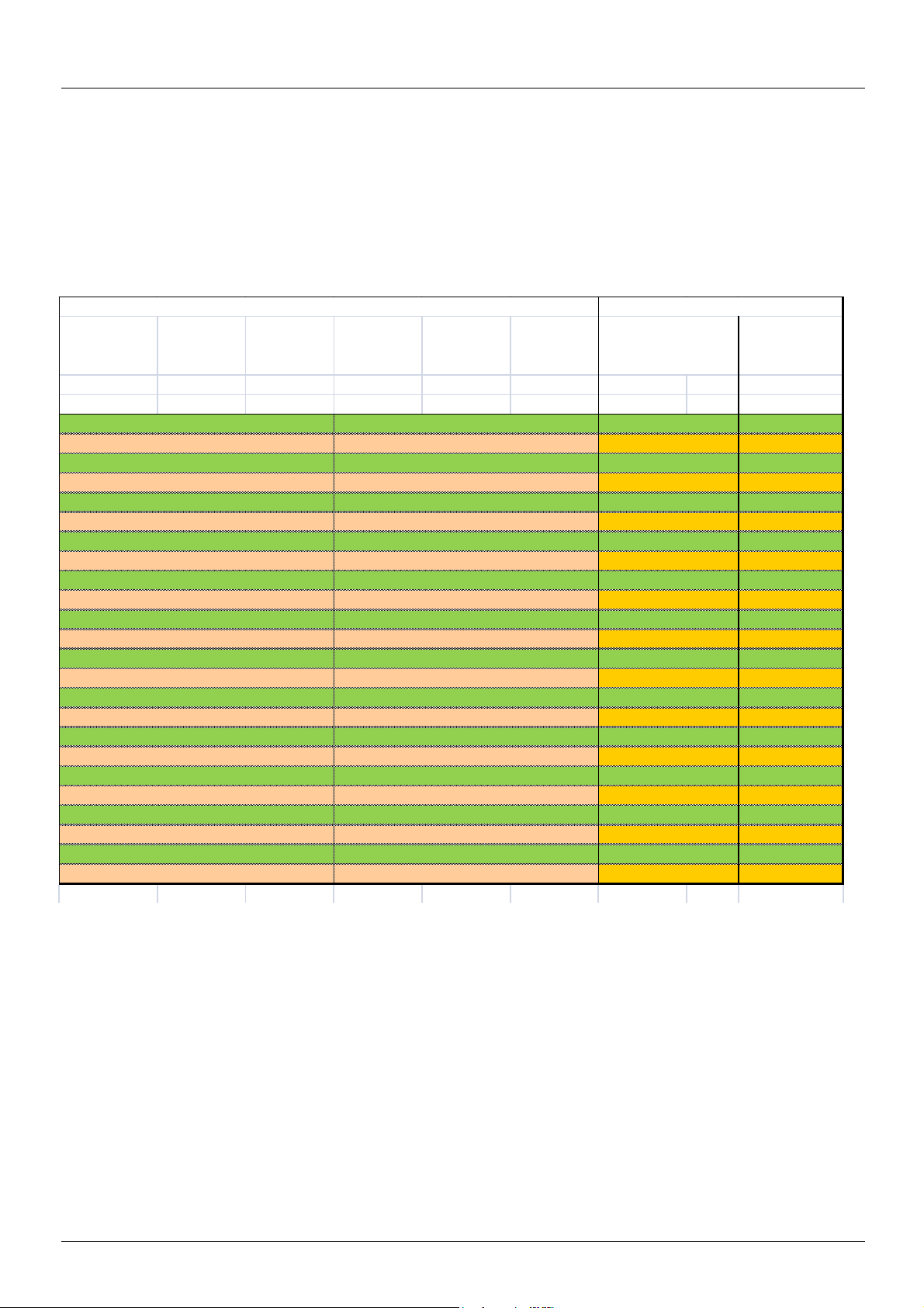
The following tables show the possible ATV 78/ATV 61 or ATV 78/ATV 71 combinations according to the torque required.
Choice of Altivar 61 or Altivar 71
Standard constant torque applications
ATV 78
(1)]Line chokes must be ordered separately.
These are optional on ATV71H U30Y to D90Y drives. On ATV71H C11Y to C63Y drives, however, they are compulsory, unless a special
transformer is used (such as a 12-pulse type).
AAV50749 12/2009 5
ATV 71
catalog number
Page 6
Determining catalog numbers
Motor power
according to
supply voltage
ATV78.(F)
catalog
number
Line choke
catalog number
(1)
kW Hp kW I nominal I max
525 V 600 V 690 V A A
1.7 2 2.2 3.2 6.7 U22Y ATV71H U22Y VW3A4551
2.3 3 3 4.5 9 U30Y ATV71H U30Y VW3A4551
3 3 4 5.5 11 U40Y ATV71H U40Y VW3A4551
4.2 5 5.5 7.5 15 U55Y ATV71H U55Y VW3A4552
5.7 7.5 7.5 10 20 U75Y ATV71H U75Y VW3A4552
8 11 11 13.5 27 D11Y ATV71H D11Y VW3A4553
11 15 15 18 36 D15Y ATV71H D15Y VW3A4553
14 20 18.5 22 44 D18Y ATV71H D18Y VW3A4554
17 25 22 27 54 D22Y ATV71H D22Y VW3A4554
23 30 30 34 68 D30Y ATV71H D30Y VW3A4555
29 40 37 41 82 D37Y ATV71H D37Y VW3A4555
34 50 45 52 104 D45Y ATV71H D45Y VW3A4555
42 60 55 62 124 D55Y ATV71H D55Y VW3A4556
57 75 75 80 160 D75Y ATV71H D75Y VW3A4556
68 100 90 100 200 D90Y ATV71H D90Y VW3A4556
84 125 110 125 250 C11Y ATV71H C11Y VW3A4570
100 150 132 144 288 C13Y ATV71H C13Y VW3A4571
122 150 160 170 340 C16Y ATV71H C16Y VW3A4571
152 200 200 208 370 C20Y ATV71H C20Y VW3A4560
190 250 250 261 440 C25Y ATV71H C25Y VW3A4572
240 300 315 325 620 C31Y ATV71H C31Y VW3A4572
270 400 355 385 770 C35Y ATV71H C40Y 2 x VW3A4568
342 450 450 460 920 C45Y ATV71H C50Y 2 x VW3A4572
380 500 500 502 1004 C50Y ATV71H C50Y 2 x VW3A4572
426 600 560 590 1180 C56Y ATV71H C63Y 2 x VW3A4572
ATV71
catalog number
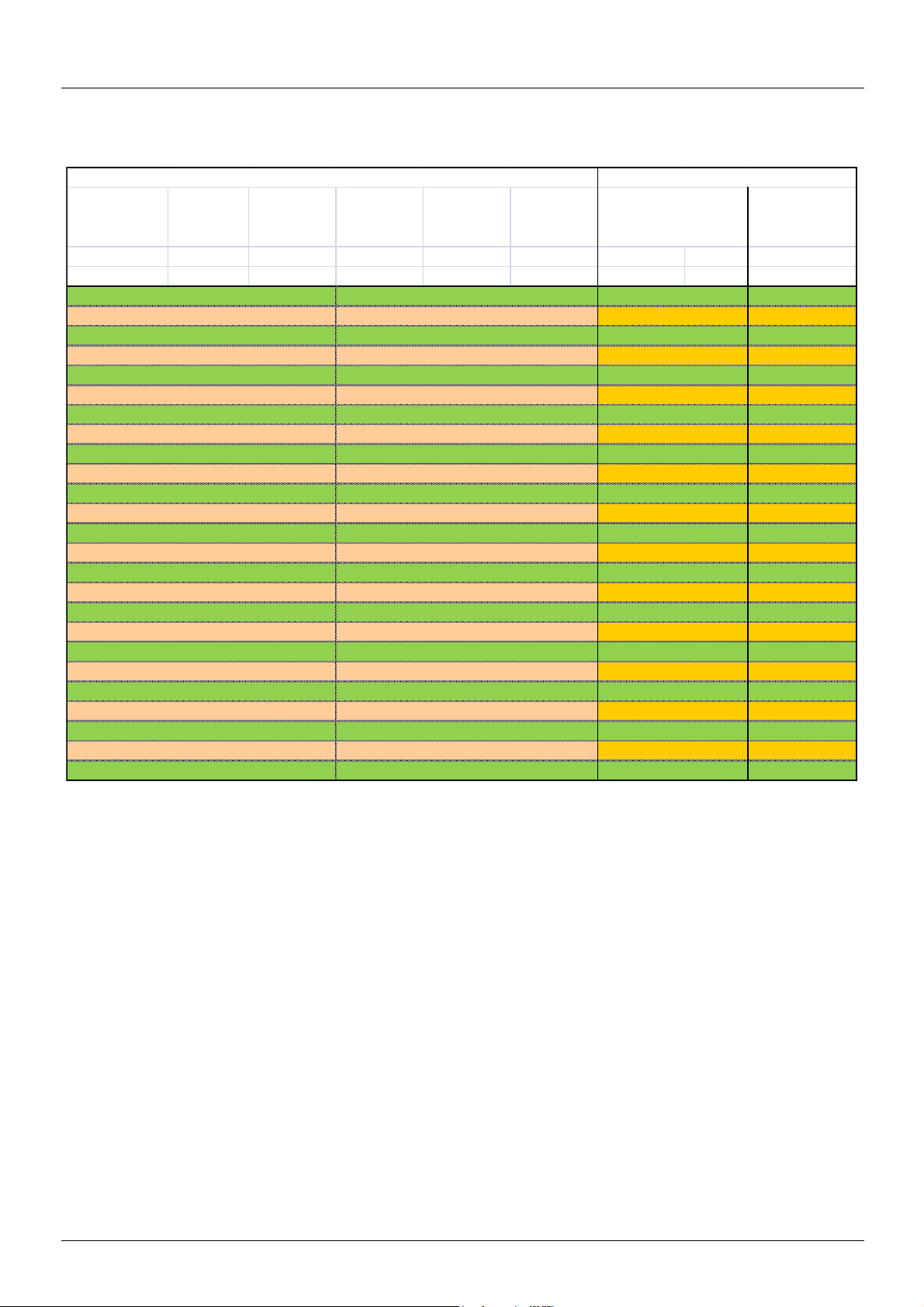
High constant torque applications
ATV 78
ATV 71
(1)Line chokes must be ordered separately.
These are optional on ATV71H U22Y to D90Y drives. On ATV71H C11Y to C63Y drives, however, they are compulsory, unless a special
transformer is used (such as a 12-pulse type).
6 AAV50749 11/2009
Page 7
Determining catalog numbers
11.4 15 15 18 27 D11Y ATV61H D15Y VW3A4553
14.1 20 18.5 22 36 D15Y ATV61H D18Y VW3A4553
16.7 25 22 27 44 D18Y ATV61H D22Y VW3A4554
22.8 30 30 34 54 D22Y ATV61H D30Y VW3A4554
28.5 40 37.5 41 68 D30Y ATV61H D37Y VW3A4555
34 50 45 52 82 D37Y ATV61H D45Y VW3A4555
42 60 55 62 104 D45Y ATV61H D55Y VW3A4555
57 75 75 80 124 D55Y ATV61H D75Y VW3A4556
68 100 90 100 160 D75Y ATV61H D90Y VW3A4556
84 125 110 125 200 D90Y ATV61H C11Y VW3A4570
100 150 132 144 250 C11Y ATV61H C13Y VW 3A4570
122 150 160 170 288 C13Y ATV61H C16Y VW 3A4571
152 200 200 208 340 C16Y ATV61H C20Y VW 3A4571
190 250 250 261 370 C20Y ATV61H C25Y VW 3A4560
240 300 315 325 440 C25Y ATV61H C31Y VW 3A4572
270 400 355 385 620 C31Y ATV61H C40Y VW 3A4572
342 450 450 460 770 C35Y ATV61H C50Y 2 x VW3A4568
380 500 500 502 920 C45Y ATV61H C50Y 2 x VW3A4568
426 600 560 590 1004 C50Y ATV61H C63Y 2 x VW3A4572
479 650 630 650 1180 C56Y ATV61H C63Y 2 x VW3A4572
540 800 710 650 1300 C63Y ATV61H C80Y 2 x VW3A4572
609 800 800 820 1500 C71Y ATV61H C80Y 2 x VW3A4572
Standard variable torque applications
The Altivar 61 is designed for pumping and ventilation applications where the torque varies with the speed.
(1)Line chokes must be ordered separately.
These are optional on ATV61H U22Y to C11Y drives. On ATV61H C13Y to C80Y drives, however, they are compulsory, unless a special
transformer is used (such as a 12-pulse type).
AAV50749 12/2009 7
Page 8

Determining catalog numbers
Selecting the power circuit options
Line chokes
Altivar 78 drives were supplied with line chokes across all ratings.
On the Altivar 71 or Altivar 61, line chokes are optional up to 90 kW (120 HP). Above this rating, however, they are compulsory, unless a
special transformer, such as a 12-pulse type, is used. Line chokes must be ordered separately (see the equivalence tables on pages 5
to 7).
Mounting accessories
Altivar 78 drives U22Y to C16Y offer IP21 degree of protection and are NEMA type 1. Altivar 61 and Altivar 71 have a different degree of
protection depending on which access panel is used (please refer to the catalog), specifically IP20 or IP00 from below depending on the
rating.
• If IP21 protection is required, add an IP21/IP31 mounting kit.
• If NEMA type 1 is required, add a NEMA type 1 mounting kit.
IP21/IP31 mounting kit
Information required: Altivar 61 or Altivar 71 catalog number
Catalog number selection guide:
ATV 61H drive ATV 71H drive IP21 kit IP31 kit
U30Y, U40Y, U55Y, U75Y, D11Y, D15Y,
D18Y, D22Y, D30Y, D37Y
D45Y, D55Y, D75Y, D90Y D37Y, D45Y, D55Y, D75Y, D90Y VW3 A9 108 C11Y, C13Y, C16Y, C20Y C11Y, C13Y, C16Y - VW3 A9 111
C25Y, C31Y, C40Y C20Y, C25Y, C31Y - VW3 A9 113
C50Y, C63Y, C80Y C40Y, C50Y, C63Y - VW3 A9 116
NEMA type 1 mounting kit
Information required: Altivar 61 or Altivar 71 catalog number
U22Y, U30Y, U40Y, U55Y, U75Y, D11Y,
D15Y, D18Y, D22Y, D30Y
VW3 A9 106 -
Catalog number selection guide:
ATV 61H drive ATV 71H drive NEMA kit
U30Y, U40Y, U55Y, U75Y, D11Y, D15Y,
D18Y, D22Y, D30Y, D37Y
D45Y, D55Y, D75Y, D90Y D37Y, D45Y, D55Y, D75Y, D90Y VW3 A9 208
C11Y, C13Y, C16Y, C20Y C11Y, C13Y, C16Y VW3 A9 211
C25Y, C31Y, C40Y C20Y, C25Y, C31Y VW3 A9 213
U22Y, U30Y, U40Y, U55Y, U75Y, D11Y,
D15Y, D18Y, D22Y, D30Y
VW3 A9 206
8 AAV50749 11/2009
Page 9

Determining catalog numbers
Control circuit option: Remote display terminal
Remote connection of the Altivar 61 or Altivar 71 graphic display terminal on the enclosure door
IP54 version Remote mounting kit : VW3 A1 102
3-meter cable : VW3 A1 104 R30
IP65 version Remote mounting kit : VW3 A1 102
IP65 door : VW3 A1 103
3-meter cable : VW3 A1 104 R30
Female/female RJ45 adapter : VW3 A1 105
This should be used in the above two instances.
Note: Order an Altivar 61 or Altivar 71 with graphic display terminal (without a Z at the end of the catalog number).
Other cable lengths are available:
Cable 1 m VW3 A1 104 R10
5 m VW3 A1 104 R50
10 m VW3 A1 104 R100
Note: The graphic display terminal catalog number is VW3 A1 101.
AAV50749 12/2009 9
Page 10

Determining catalog numbers
Choice of I/O extension cards
Drive or
extension card
catalog number
ATV 7862121
VW3A78203 2 1
VW3A78204 3
VW3A78205 3
VW3A78206 6 2 1 1
VW3A78207 2
VW3A78208 3
VW3A78209 5 1
VW3A78210 1 2
VW3A78211 3
ATV 61/71 6 2 2 1 1
VW3A3201 4 2 1 1
VW3A3202422121
VW3A340
For more information, please refer to the catalog.
Logic inputs Analog inputs Logic outputs Relay outputs Analog outputs Inputs for PTC
p 1
probes
Inputs for
PT100 probes
Encoder inputs
10 AAV50749 11/2009
Page 11

Drive setup
Mounting: Standard torque applications
Comparison of dimensions
Width (mm) Height (mm) Depth (mm)
ATV78 HU22Y 195 558 237
ATV71 HU22Y 240 420 236
ATV61 HU30Y 240 420 236
ATV78 HU30Y 195 558 237
ATV71 HU30Y 240 420 236
ATV61 HU40Y 240 420 236
ATV78 HU40Y 195 558 237
ATV61 HU40Y 240 420 236
ATV61 HU55Y 240 420 236
ATV78 HU55Y 195 558 237
ATV71 HU55Y 240 420 236
ATV61 HU75Y 240 420 236
ATV78 HU75Y 195 558 237
ATV71 HU75Y 240 420 236
ATV61 HD11Y 240 420 236
ATV78 HD11Y 195 558 237
ATV71 HD11Y 240 420 236
ATV61 HD15Y 240 420 236
ATV78 HD15Y 195 558 237
ATV71 HD15Y 240 420 236
ATV61 HD18Y 240 420 236
ATV78 HD18Y 195 558 237
ATV71 HD18Y 240 420 236
ATV61 HD22Y 240 420 236
ATV78 HD22Y 195 558 237
ATV71 HD22Y 240 420 236
ATV61 HD30Y 240 420 236
ATV78 HD30Y 237 630 257
ATV71 HD37Y 320 630 290
ATV61 HD37Y 320 630 290
To determine the correspondence between standard and constant torque
AAV50749 12/2009 11
Page 12

Drive setup
H
c
a
4xØ9
G
b
2xØ12
325
500
5040
850
57
879242
17
3030
425
2xØ23
2xØ12
455
1165
506
15
150
275
30
a
120 120
b1
b
G
c
c1
6xØ
8xØ9x14
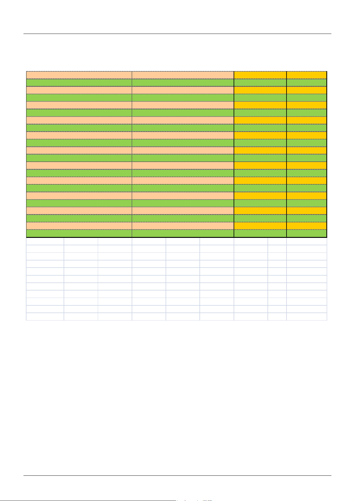
Comparison of dimensions
ATV 78p(F)U22Y to ATV 78p(F)C16Y (line choke supplied pre-installed)
ATV 78p, ATV 78pF a b c G H
U22Y…D22Y 195 558 237 148 541
D30Y…D37Y 237 630 257 190 614
D45Y…D75Y 289 755 344 255 732
D90Y…C16Y 480 1150 362 400 1120
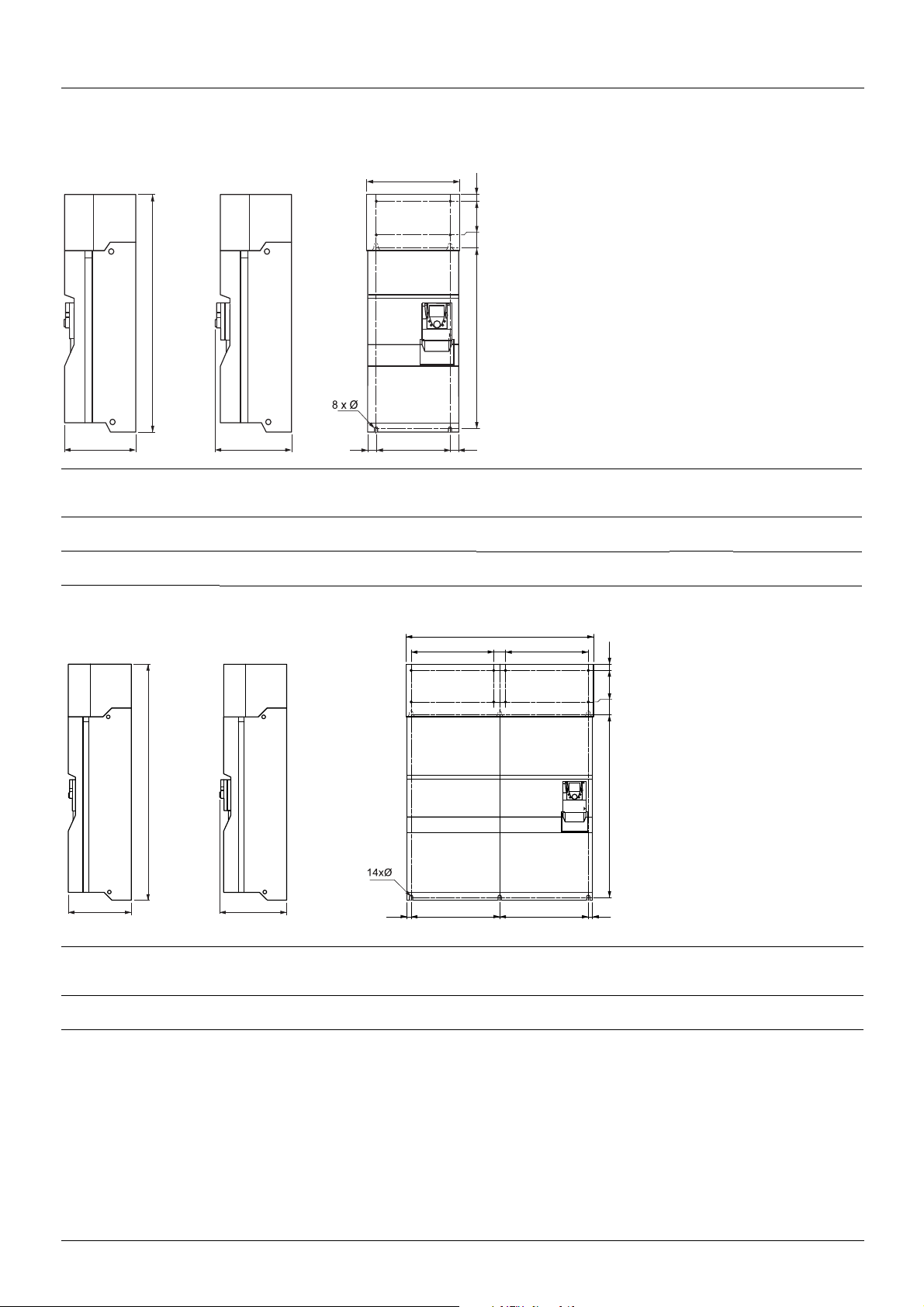
ATV 780(F)C20Y to ATV 780(F)C31Y (line choke supplied with drive but not pre-installed)
Line choke
12 AAV50749 11/2009
For ATV 78 drives a b b1 c c1 G Ø
0C20Y,
0FC20Y
0C25Y…0C31Y
0FC25Y…0FC31Y
354 357 319 230 206 108 9x14
350 421 383 262 238 140 11x15
Page 13

Drive setup
468
709
1206
240
506
850
225 225 67
225 225 67
6xØ12
22 2
200
145
244
204
40
20
399
446
497
165 165
6xØ11x15
4xØ13
6xØ11x15
30
15
150
275
350
120 120
140
262
421
383
238
8xØ9x14
Variable speed drives (continued)
ATV 780(F)C35Y to ATV 780(F)C50Y (line choke supplied with drive but not pre-installed)
Terminal cover removed
Line choke for ATV 780(F)C35Y and ATV 780(F)C45Y drives
Line choke for ATV 780(F)C50Y drives (1)
(1) Two line chokes are supplied with the drive.
AAV50749 12/2009 13
Page 14

Drive setup
455
1165
506
2xØ12
325
500
5040
850
57
879242
17
3030
425
2xØ23
2xØ12
6xØ11x15
30
15
150
275
350
120 120
140
262
421
383
238
8xØ9x14
Variable speed drives (continued)
ATV 780(F)C56Y to ATV 780(F)C71Y (1) (line choke supplied with drive but not pre-installed)
(1) Two power units and one control unit are supplied with the drive.
Line choke (1)
(1) Two line chokes are supplied with the drive.
14 AAV50749 11/2009
Page 15

Drive setup
With 2 option cards (1)
With 1 option card (1)
No option card
c
c1
c2
G
a
=
=
H
h
b
4 x
With 2 option cards (1)
With 1 option card (1)
No option card
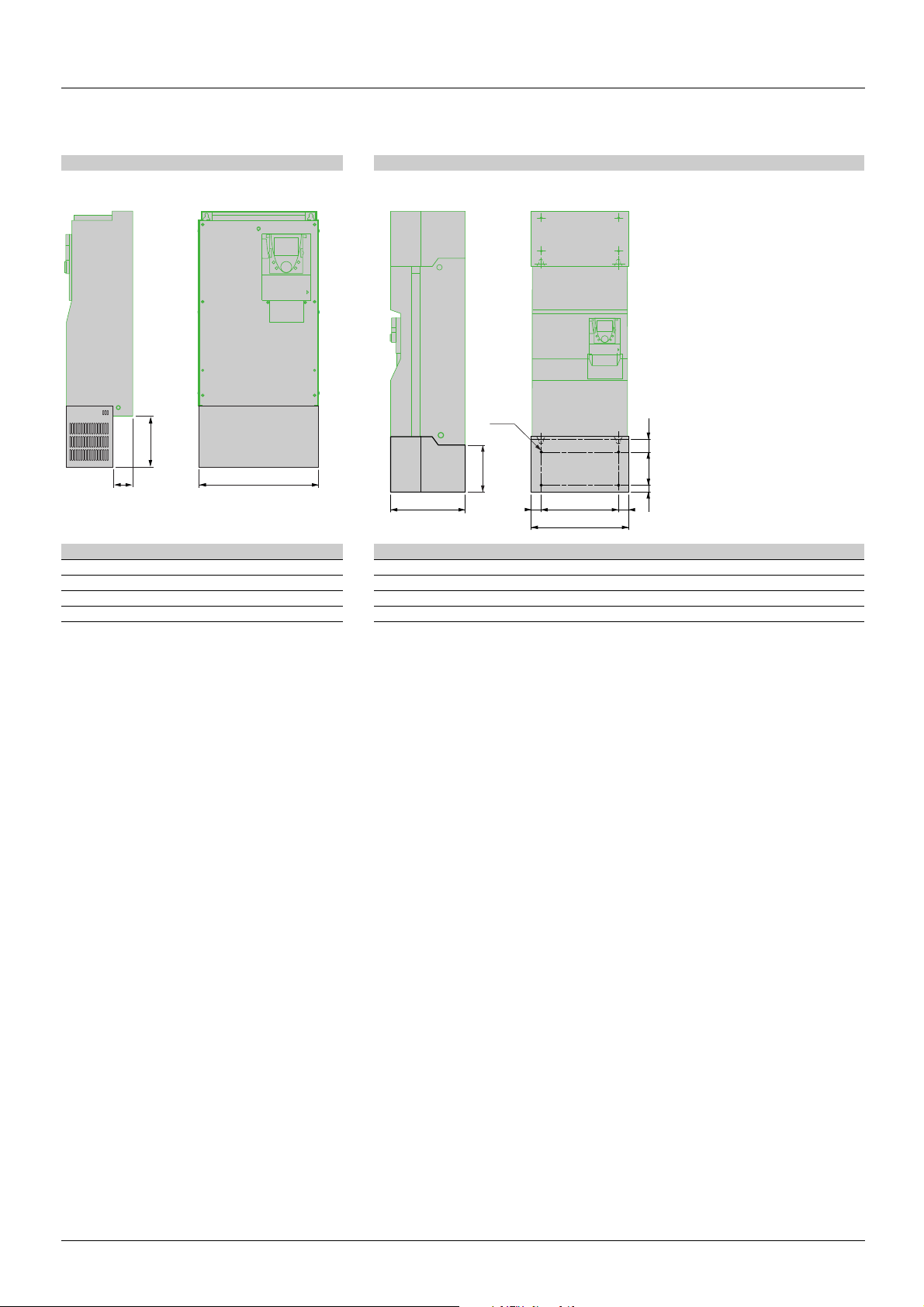
ATV 61/ATV 71 with graphic display terminal
ATV61H/ATV71H a
mm
(in.)
ATV61H U30Y to D30Y,
ATV71H U22Y to D30Y
ATV61H D37Y to D90Y,
ATV71H D37Y to D90Y
240
(9.45)
320
(12.60)
b
mm
(in.)
420
(16.54)
630
(24.80)
c
mm
(in.)
236
(9.29)
290
(11.42)
c1
mm
(in.)
259
(10.20)
313
(12.32)
c2
mm
(in.)
282
(11.10)
334
(13.15)
G
mm
(in.)
206
(8.11)
280
(11.02)
H
mm
(in.)
h
mm
(in.)
Ø
mm
(in.)
403
(15.87)11(0.45)6(0.24)
604.5
(23.80)15(0.59)9(0.35)
For
screws
M5 30
M8 45
Weight
kg
(lb.)
(66.14)
(99.21)
ATV 61/ATV 71 without graphic display terminal
For a drive without a graphic display terminal, dimensions c, c1 and c2 in the table above are reduced by 26 mm (1.01 in.). The other
dimensions are unchanged.
(1)For the addition of I/O extension cards, communication cards, or the "Controller Inside" programmable card.
AAV50749 12/2009 15
Page 16
Drive setup
With 2 option cards (1)With 0 or 1 option card (1)
ATV61H C11Y to C80Y,
ATV71H C11Y to C63Y
G=G=
J1 J J1
a
b
377 mm
(14.77 in)
392 mm
(15.43 in)
K2KK1H
With 2 option cards (1)With 0 or 1 option card (1)
ATV61H C50Y to C80Y,
ATV71H C40Y to C63Y
ATV 61/ATV 71
b
a
HK1KK2
377 mm
(14.77 in)
392 mm
(15.43 in)
ATV61H/ATV71H a
mm
(in.)
ATV61H C11Y to C20Y,
ATV71H C11Y to C16Y
ATV61H C25Y to C40Y,
ATV71H C20Y to C31Y
340
(13.39)
595
(23.43)
b
mm
(in.)
1190
(46.62)
1190
(46.62)
==G
G
mm
(in.)
285
(11.22)
540
(21.26)
H
mm
(in.)
920
(36.22)
920
(36.22)
K
mm
(in.)
K1
mm
(in.)
K2
mm
(in.)
150
(5.91)75(2.95)30(1.18)
150
(5.91)75(2.95)30(1.18)
Ø
mm
(in.)
11.5
(0.45)
11.5
(0.45)
For
Weight
screws
M10 110
M10 190
kg
(lb.)
(242)
(418)
For
ATV61H/ATV71H a
ATV61H C50Y to C80Y,
ATV71H C40Y to C63Y
mm
(in.)
1120
(44.09)
b
mm
(in.)
1390
(54.72)
G
mm
(in.)
J
mm
(in.)
532.5
(20.96)70(2.76)
J1
mm
(in.)
495
(1949)
H
mm
(in.)
1120
(44.09)
K
mm
(in.)
K1
mm
(in.)
mm
(in.)
150
(5.91)75(2.95)30(1.18)
K2
Ø
mm
(in.)
11.5
(0.45)
screws
Weight
kg
(lb.)
M10 400
(880)
(1)For the addition of I/O extension cards, communication cards, or the "Controller Inside" programmable card.
16 AAV50749 11/2009
Page 17
Drive setup
a
c
b
G
K2
K
K1
4xØ
b
c
a
==
ATV 61/ATV 71 - IP 21 or IP 31 conformity kits (VW3 A9 1pp), UL Type 1 conformity kits (VW3 A9 2pp)
VW3 A9 106, 108, 206, 208 VW3 A9 111, 112, 211, 212
VW3 a b c VW3 a b c G K K1 K2 Ø
A9 106 240 75 102 A9 111 345 315 377 285 250 65 75 11.5
A9 108 320 163 102 A9 112 445 375 377 350 250 65 75 11.5
A9 206 240 59.9 102 A9 211 345 315 377 285 250 65 75 11.5
A9 208 320 136 102 A9 212 445 375 377 350 250 65 75 11.5
AAV50749 12/2009 17
Page 18
Drive setup
115
100
8xØ4,5…5
8144
37,5
100
175
135
115 mm (4.53 in)
104 mm (4.09 in)
115 mm (4.53 in)
100 mm (3.93 in) 5 mm (0.2 in)
4 x ∅ 3 mm
(0.12 in)
R
U
N
STOP
RESET
F
2
F
1
F
3
F
4
E
S
C
FW
D
REV
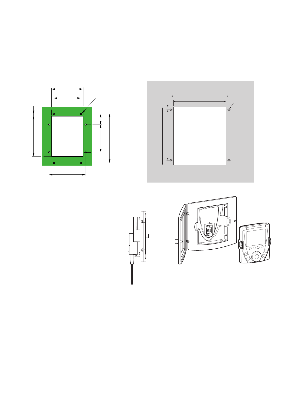
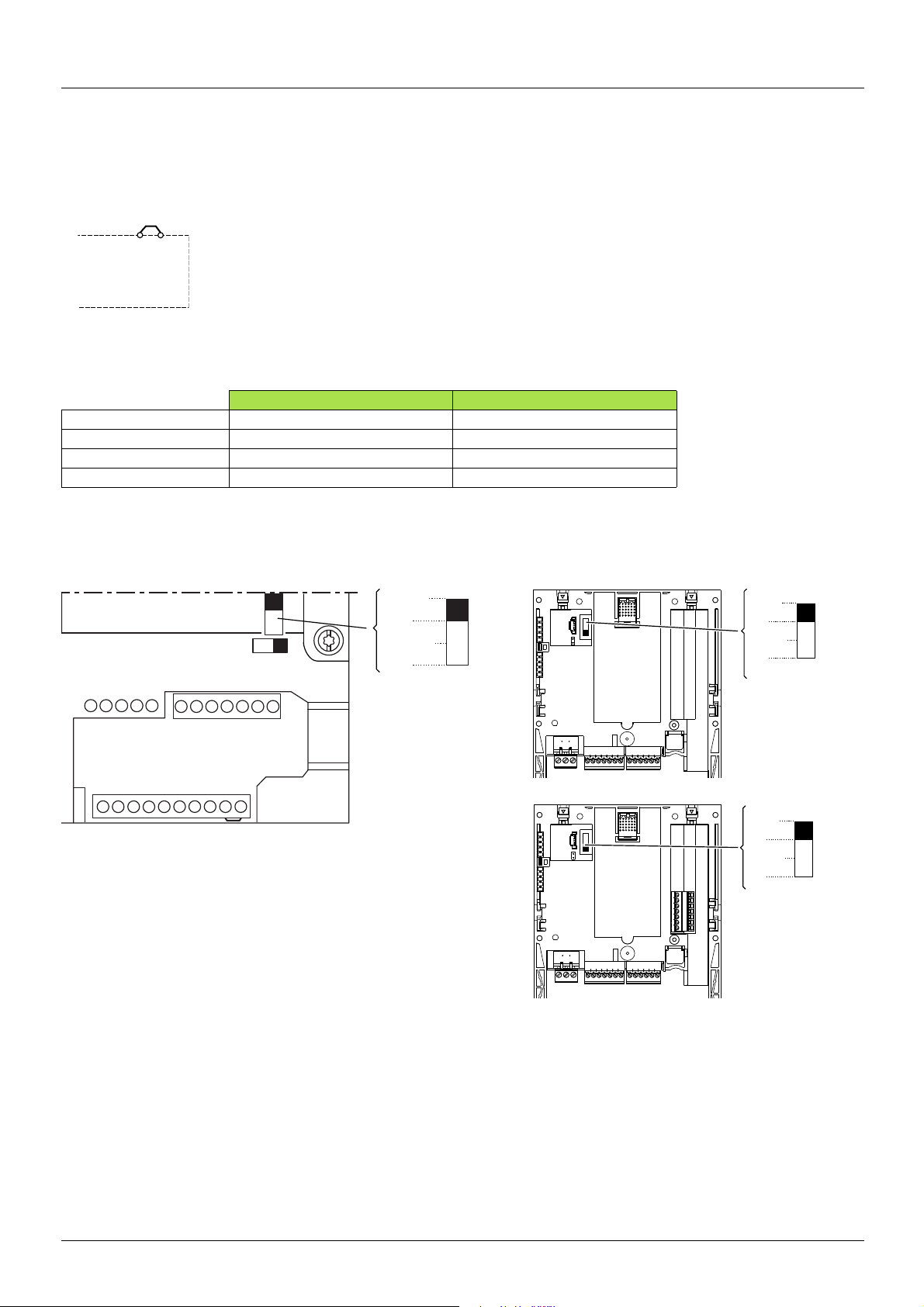
Remote display terminal
Used to connect the programming terminal remotely on the front of the enclosure.
Mounting:
As the dimensions are not the same, the drill holes must be modified.
ATV 78 ATV 71
18 AAV50749 11/2009
Page 19
Drive setup
U
V
W
L1
U1
W1
V1
M
3 a
L2
L3
A1
RO2
RO2
R-
R+
RO1
RO1
RO1
ATV78pppppp
RO2
(1)
Braking resistor
(if used)
ATVp1HpppY
U / T1
V / T2
W / T3
R / L1
M
3 a
S / L2
T / L3
A1
R1A
R1C
R1B
R2A
R2C
U1
W1
V1
PWR
+24
P0
PA / +
PB
PC / -
(2)
Braking resistor
(if used)
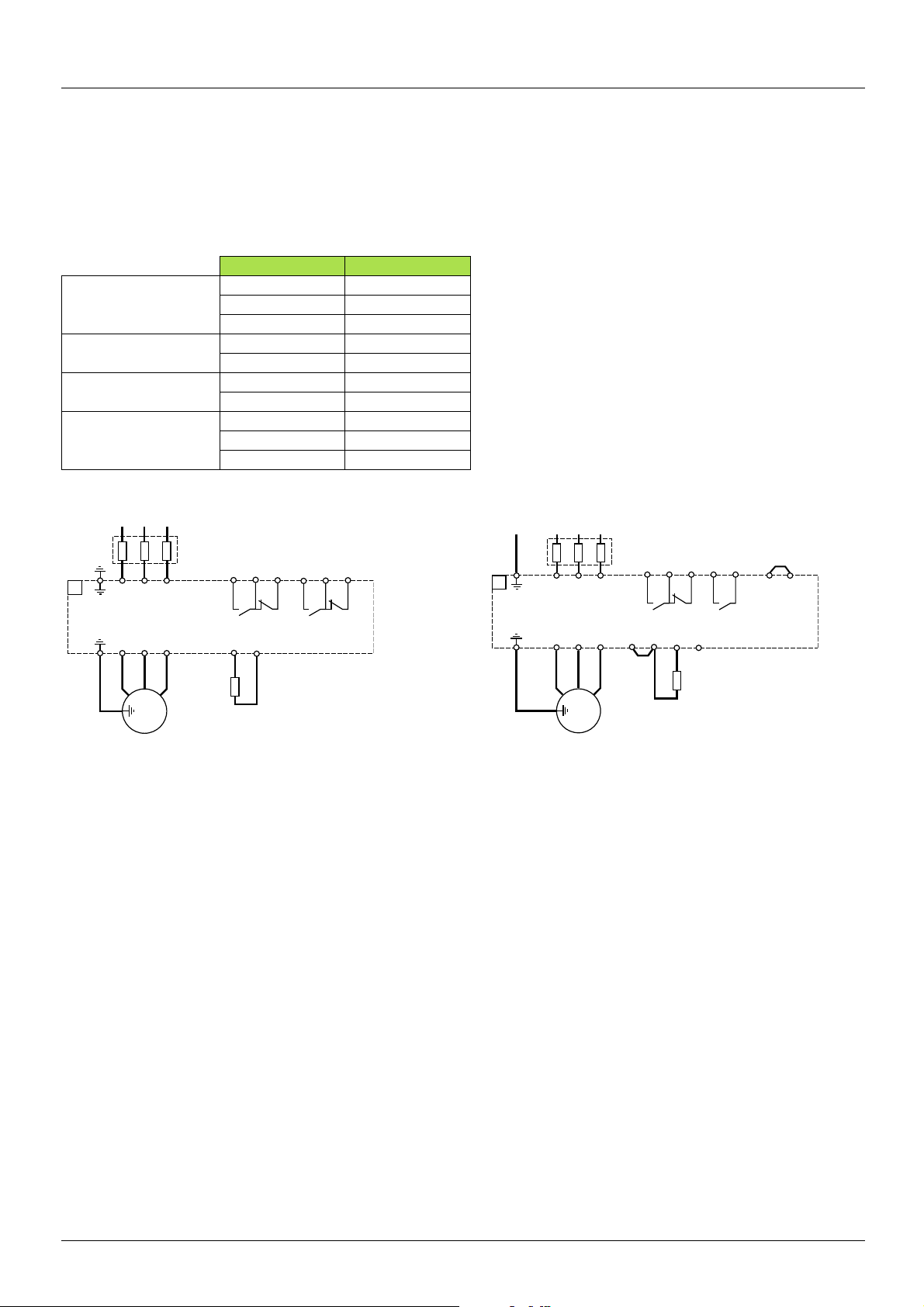
Power section wiring
The layout and type of power terminals have changed.
Ring terminals must be used rather than ferrules for the ground terminals, although for the power terminals the ferrules used previously can
be retained if they are in good condition (a flattened ferrule will not make a good connection).
Table of correspondence for power terminals
ATV 78 ATV 61/ATV 71
Power supply L1 R/L1
L2 S/L2
L3 T/L3
DC bus B+ PO
B- PC/-
Braking resistor R+ PA/+
R- PB
Motor output U U/T1
VV/T2
WW/T3
Connecting the Altivar 78 Connecting the Altivar 61 or Altivar 71
(1)Line choke, installed and wired separately for ATV780C20Y rating and above
(2)Line choke to be mounted and wired separately
Disconnecting the RFI filter if using an IT system
IT system: Isolated or impedance grounded neutral
Use a permanent insulation monitor compatible with non-linear loads, such as a Merlin Gerin type XM200 or equivalent.
Altivar 61 and 71 drives feature built-in RFI filters. When using Altivar 61 and 71 drives on an IT system, the link between these filters and
ground must be removed. Please refer to the Installation Manual on the CD-ROM supplied with the drive.
Corner grounded system: System with one phase connected to ground
ATV61H...Y and ATV71H...Y drives must not be connected to a corner grounded system.
Arrangement and characteristics of ATV 61 and ATV 71 power terminals
Please refer to the Installation Manual on the CD-ROM supplied with the drive.
AAV50749 12/2009 19
Page 20
Drive setup
ATVp1HpppM3
PWR
+24
R1B
R1A
R1C
R2A
R2C
AI1+
+10
AI1-
COM
AI2
COM
AO1
0V
P24
LI1
LI2
LI3
LI4
LI5
LI6
+24
PWR
RJ45
SW1
SW2
Ext
Source
Sink
Int
SW3
Ext
Source
Sink
Int
SW4
Ext
Source
Sink
Int
VW3 A3 201
VW3 A3 202
Control section wiring and I/O characteristics
Caution: Check the I/O assignments.
In order to ensure that the Altivar 61 or 71 functions correctly, the following rules must be adhered to:
• Check that the strap is present between +24 and PWR.
• The PTC probes connected to an ATV 61 or ATV 71 correspond to the market standard. Check that the trip thresholds are suitable for
the temperature levels supported by the motor.
ATV 78 value (kOhms) ATV 61/ATV 71 value (kOhms)
Probe short-circuit - < 0.05
Reset - 1.8
Overheating 4.7 3
Probe break - > 100
• Check that switch SW1 on the Altivar 61 or 71 and switches SW3 and SW4 on the option cards correspond with the position of jumpers
CMA and CMB (group of jumpers (X3) on the base card) on the Altivar 78 and that the connections comply with the recommendations
on the next page.
20 AAV50749 11/2009
Page 21
Drive setup
DI1
GND
DI2
DI3
Position (CMA grounded)
+ 24 V/Internal + 24 V
A1
ATV71Hppppp
SW1
Ext
Source
Sink
Int
LI1
LI5
+24
0V
LI3
LI2
LI6
LI4
DI1
GND
DI2
DI3
Position (CMA isolated)
External
+ 24 V + 24 V/Internal + 24 V
Weight
A1
ATV71Hppppp
SW1
Ext
Source
Sink
Int
LI1
LI5
+24
0V
LI3
LI2
LI6
LI4
+24 V
0 V
24 V c supply
DI1
DI2
DI3
Position (CMA isolated)
External
+ 24 V
+ 24 V/External + 24 V
Weight
A1
ATV71Hppppp
SW1
Ext
Source
Sink
Int
LI1
LI5
+24
0V
LI3
LI2
LI6
LI4
+24 V
0 V
24 V c supply
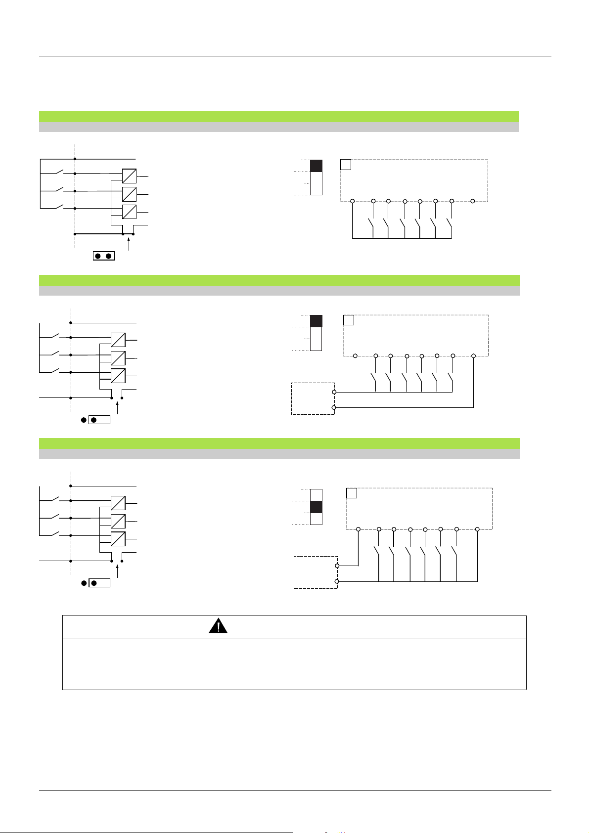
Control section and option card logic input wiring
Examples of correspondence of various jumper positions to ensure equivalent operation:
ATV 78 ATV 61 or ATV 71 correspondence
With + 24 V internal power supply
• Switch SW1 set to "Source" position
ATV 78 ATV 61 or ATV 71 correspondence
With external + 24 V power supply. Positive logic
• Switch SW1 set to "Source" position
ATV 78 ATV 61 or ATV 71 correspondence
With external + 24 V power supply. Negative logic
Unintended equipment operation
When switch SW1 is set to "Sink Int" or "Sink Ext", the common must never be connected to ground or the protective ground, as there is
then a risk of unintended equipment operation on the first insulation fault.
Failure to follow this instruction can result in death or serious injury.
Wiring other I/O
Please refer to the catalog, the Installation Manual and the Programming Manual on the CD-ROM supplied with the drive.
AAV50749 12/2009 21
• Switch SW1 set to "Sink Ext" position
WARNING
Page 22

ATV78-61/71_migration_EN_AAV50749_02
AAV50749 12/2009
 Loading...