

Page 1
2354235 11/2008
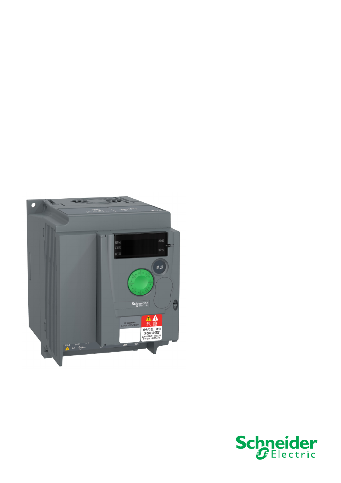
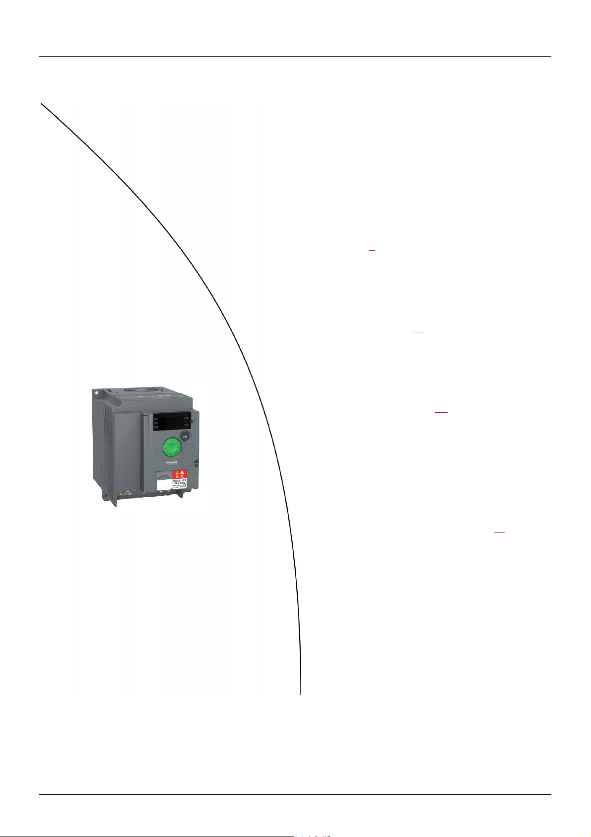
Easy Altivar ATV310
Variable speed drives for asynchronous motors
User manual
11/2020
380 V...460 V three-phase, power rating 0.37 kW to 22 kW
EAV94277
www.schneider-electric.com
Page 2

Page 3

Contents
Contents ____________________________________________________________________________________________________ 3
Important information __________________________________________________________________________________________ 4
Before you begin______________________________________________________________________________________________ 5
Documentation structure________________________________________________________________________________________ 8
Steps for setting up (also refer to Quick Start)_________________________________________________________ 9
Setup - Preliminary recommendations ____________________________________________________________________________ 10
Drive& ratings _______________________________________________________________________________________________ 11
Dimensions and weights_______________________________________________________________________________________ 13
Environmental Conditions______________________________________________________________________________________ 15
Mounting___________________________________________________________________________________________________ 17
Wiring _____________________________________________________________________________________________________ 20
Power terminals _____________________________________________________________________________________________ 26
Control terminals_____________________________________________________________________________________________ 31
Check list Before Switching On _________________________________________________________________________________ 36
Factory configuration _________________________________________________________________________________________ 37
Basic functions ______________________________________________________________________________________________ 38
Programming _______________________________________________________________________________________________ 39
Structure of parameter tables___________________________________________________________________________________ 42
Function compatibility table ____________________________________________________________________________________ 43
Reference Mode rEF _________________________________________________________________________________________ 44
Monitoring mode MOn ________________________________________________________________________________________ 45
Configuration mode, ConF _____________________________________________________________________________________ 52
Configuration Mode __________________________________________________________________________________________ 53
Configuration Mode - Complete menu (FULL) ______________________________________________________________________ 54
Maintenance _______________________________________________________________________________________________ 111
Diagnostics and Troubleshooting _______________________________________________________________________________ 114
Application notes ___________________________________________________________________________________________ 120
Parameter index ____________________________________________________________________________________________ 126
EAV94277 11/2020 3
Page 4
Important information
The addition of this symbol to a Danger or Warning safety label indicates that an electrical hazard exists, which will result in personal
injury if the instructions are not followed.
This is the safety alert symbol. It is used to alert you to potential injury hazards that exist at this point. Obey all safety messages that
follow this symbol to avoid possible injury or death.
NOTICE
Read these instructions carefully, and become familiar with the device before trying to install, operate, or maintain it. The following special
messages may appear throughout this documentation or on the equipment to warn of potential hazards or to call attention to information
that clarifies or simplifies a procedure.
DANGER
DANGER indicates an imminently hazardous situation, which, if not avoided, will result in death or serious injury.
WARNING
WARNING indicates a potentially hazardous situation which, if not avoided, can result in death, serious injury or
equipment damage.
CAUTION
CAUTION indicates a potentially hazardous situation which, if not avoided, can result in injury or equipment damage.
NOTICE
Notice, used without the safety alert symbol, indicates a potentially hazardous situation which, if not avoided, can
result in equipment damage.
PLEASE NOTE
The word "drive" as used in this manual refers to the controller of the adjustable speed drive as defined by NEC.
Electrical equipment should be installed, operated, serviced, and maintained only by qualified personnel. No responsibility is assumed by
Schneider Electric for any consequences arising out of the use of this product.
© 2020 Schneider Electric. All Rights Reserved.
4 EAV94277 11/2020
Page 5
Before you begin
Read and understand these instructions before performing any procedure with this drive.
DANGER
HAZARD OF ELECTRIC SHOCK, EXPLOSION OR ARC FLASH
• Only appropriately trained persons who are familiar with and fully understand the contents of the present manual and all other
pertinent product documentat ion and who have received all necessary training to recognize and avoid hazards involved are authorized
to work on and with this drive system.
• Installation, adjustment, repair and maintenance must be performed by qualified personnel.
• Verify compliance with all local and national electrical code requirements as well as all other applicable regulations with respect to
grounding of all equipment.
• Only use properly rated, electrically insulated tools and measuring equipment.
• Do not touch unshielded components or terminals with voltage present.
• Prior to performing any type of work on the drive system, block the motor shaft to prevent rotation.
• Insulate both ends of unused conductors of the motor cable.
• Do not short across the DC bus terminals or the DC bus capacitors or the braking resistor terminals.
• Before performing work on the drive system:
- Disconnect all power, including external control power that may be present.
- Place a "Do Not Turn On" label on all power switches.
- Lock all power switches in the open position.
- Wait 15minutes to allow the DC bus capacitors to di scharge. The DC bus LED is not an indicator of the ab sence of DC bus voltage
that can exceed 800Vdc.
- Verify that no other voltage is present in the drive system.
• Before applying voltage to the drive system:
- Verify that the work has been completed and that the entire installation cannot cause hazards.
- If the mains input terminals and the motor output terminals have been grounded and short-circuited, remove the ground and
the short circuits on the mains input terminals and the motor output terminals.
- Verify proper grounding of all equipment.
• Verify that all protective equipment such as covers, doors, grids is installed and/or closed.
Failure to follow these instructions will result in death or serious injury.
WARNING
UNEXPECTED MOVEMENT
Drive systems may perform unexpected movements because of incorrect wiring, incorrect settings, incorrect data or other errors.
• Carefully install the wiring in accordance with the EMC requirements.
• Do not operate the product with unknown or unsuitable settings or data.
• Perform a comprehensive commissioning test.
Failure to follow these instructions can result in death, serious injury, or equipment damage.
Damaged products or accessories may cause electric shock or unanticipated equipmentoperation.
DANGER
ELECTRIC SHOCK OR UNANTICIPATED EQUIPMENT OPERATION
Do not use damaged products or accesssories.
Failure to follow these instructions will result in death or serious injury.
Contact your local Schneider Electric sales office if you detect any damage whatsoever.
NOTICE
RISK OF DAMAGE TO THE DRIVE
The drive should be cleaned and maintained on a regular basis when operating in high temperature, humid, greasy, chemical, dusty or
vibrating environments to prevent reduced driver lifespan and equipment damage.
Failure to follow these instructions can result in equipment damage.
EAV94277 11/2020 5
Page 6

Before you begin
WARNING
LOSS OF CONTROL
• The designer of any control scheme must consider the potential failure modes of control paths and, for critical control functions,
provide a means to achieve a safe state during and after a path failure. Examples of critical control functions are emergency stop,
overtravel stop, power outage, and restart.
• Separate or redundant control paths must be provided for critical control functions.
• System control paths may include communication links. Consideration must be given to the implications of unanticipated transmission
delays or failures of the link.
• Observe all accident prevention regulations and local safety guidelines. (a)
• Each implementation of the product must be individually and thoroughly tested for proper operation before being placed into service.
Failure to follow these instructions can result in death, serious injury or equipment damage.
a. For USA: Additional information, refer to NEMA ICS 1.1 (latest edition), “Safety Guidelines for the Application, Installation, and
Maintenance of Solid State Control” and to NEMA ICS 7.1 (latest edition), “Safety Standards for Construction and Guide for Selection,
Installation and Operation of Adjustable Speed Drive Systems.”
NOTICE
DESTRUCTION DUE TO INCORRECT MAINS VOLTAGE
Before switching on and configuring the product, verify that it is approved for the mains voltage.
Failure to follow these instructions can result in equipment damage.
This equipment has been designed to operate outside of any hazardous location. Only install this equipment in zones known to be free of a
hazardous atmosphere.
DANGER
POTENTIAL FOR EXPLOSION
Install and use this equipment in non-hazardous locations only.
Failure to follow these instructions will result in death or serious injury.
Your application consists of a whole range of different interrelated mechanical, electrical, and electronic components, the drive being just one part of
the application. The drive by itself is neither intended to nor capable of providing the entire functionality to meet all safety-related requirements that
apply to your application. Depending on the application and the corresponding risk assessment to be conducted by you, a whole variety of additional
equipment is required such as, but not limited to, external encoders, external brakes, external monitoring devices, guards, etc.
As a designer/manufacturer of machines, you must be familiar with and observe all standards that apply to your machine. You must conduct a risk
assessment and determine the appropriate Performance Level (PL) and/or Safety Integrity Level (SIL) and design and build your machine in
compliance with all applicable standards. In doing so, you must consider the interrelation of all components of the machine. In addition, you must
provide instructions for use that enable the user of your machine to perform any type of work on and with the machine such as operation and
maintenance in a safe manner.
The present document assumes that you are fully aware of all normative standards and requirements that apply to your application. Since the drive
cannot provide all safety-related functionality for your entire application, you must ensure that the required Performance Level and/or Safety Integrity
Level is reached by installing all necessary additional equipment.
WARNING
INSUFFICIENT PERFORMANCE LEVEL/SAFETY INTEGRITY LEVEL AND/OR UNINTENDED EQUIPMENT
OPERATION
• The designer of any control scheme must consider the potential failure modes of control paths and, for critical control functions,
provide a means to achieve a safe state during and after a path failure. Examples of critical control functions are emergency stop,
overtravel stop, power outage, and restart.
• Conduct a risk assessment according to EN ISO 12100 and all other standards that apply to your application.
• Use redundant components and/or control paths for all critical control functions identified in your risk assessment.
• If moving loads can result in hazards, for example, slipping or falling loads, operate the drive in closed loop mode.
• Verify that the service life of all individual components used in your application is sufficient for the intended service life of your overall
application.
• Perform extensive commissioning tests for all potential error situations to verify the effectiveness of the safety-related functions and
monitoring functions implemented, for example, but not limited to, speed monitoring by means of encoders, short circuit monitoring
for all connected equipment, correct operation of brakes and guards.
• Perform extensive commissioning tests for all potential error situations to verify that the load can be brought to a safe stop under all
conditions.
Failure to follow these instructions can result in death, serious injury or equipment damage.
6 EAV94277 11/2020
Page 7
Before you begin
Machines, controllers, and related equipment are usually integrated into networks. Unauthorized persons and malware may gain access to the
machine as well as to other devices on the network/fieldbus of the machine and connected networks via insufficiently secure access to
software and networks.
WARNING
UNAUTHORIZED ACCESS TO THE MACHINE VIA SOFTWARE AND NETWORKS
• In your hazard and risk analysis, consider all hazards that result from access to and operation on the network/fieldbus and develop an
appropriate cybersecurity concept.
• Verify that the hardware infrastructure and the software infrastructure into which the machine is integrated as well as all organizational
measures and rules covering access to this infrastructure consider the results of the hazard and risk analysis and are implemented
according to best practices and standards covering IT security and cybersecurity, such as:
• ISO/IEC 27000 series, ISO/ IEC 15408, IEC 62351, ISA/IEC 62443,
•NIST Cybersecurity Framework,
• Information Security Forum - Standard of Good Practice for Information Security,
• Schneider Electric
• Verify the effectiveness of your IT security and cybersecurity systems using appropriate, proven methods.
Failure to follow these instructions can result in death, serious injury or equipment damage.
Recommended Cybersecurity Best Practices.
WARNING
LOSS OF CONTROL
Perform a comprehensive commissioning test to verify that communication monitoring properly detects communication interruptions.
Failure to follow these instructions can result in death, serious injury or equipment damage.
Using motors in parallel
Set Motor control type 309 (page 66) to 03.
Motor thermal monitoring is no longer provided by the drive.
NOTICE
MOTOR OVERHEATING
Install external thermal monitoring equipment under the following conditions:
If several motor are connected to the same drive, Install external thermal monitoring equipment for each motor
Failure to follow these instructions can result in equipment damage.
EAV94277 11/2020 7
Page 8

Documentation structure
The following Altivar 310 technical documents are available on the Schneider Electric website (www.schneider-electric.cn).
ATV310 Quick Start Guide EAV96127 (Chinese), EAV96135 (English)
The Quick Start Guide is delivered with the drive and describe s how to wire and configure the drive to start motor quickly and simply for simple
applications.
ATV310 Complete Parameters list EAV96129 (Chinese), EAV96136 (English)
This manual gives the full parameter list of the drive in english and in Chinese.
ATV310 User manual EAV94276 (Chinese), EAV94277 (English)
This manual describes how to install, program and operate the drive.
ATV310 Modbus Communication manual (EAV94278)
This manual describes the assembly, connection to the bus or network, signaling, diagnostics, and configuration of the communicationspecific parameters via the 7 segment LED display.
It also describes the communication services of the Modbus protocol.
This manual includes all Modbus addresses. It explains the operating mode specific to communication (state chart).
ATV310 Modbus parameters description file (EAV94279)
All the parameters are grouped together in an Excel file with the following data:
•Code
•Name
• Modbus Addresses
•Category
• Read/write access
• Type: signed numerical, unsigned numerical, etc.
•Unit
•Factory setting
• Minimum value
• Maximum value
• Display on the 7-segment integrated display terminal
• Relevant menu
• This file offers the option of sorting and arranging the data according to any criterion chosen by the user.
8 EAV94277 11/2020
Page 9
Steps for setting up (also refer to Quick Start)
1. Receive and inspect the drive
v Check that the part number printed on the label is the same as that on the
purchase order.
v Remove the ATV310 from its packaging and check that it has not been damaged in
transit.
2. Check the line voltage
v Check that the line voltage is compatible with the voltage
range of the drive (page 9
).
3. Mount the drive
v Mount the drive in accordance with the instructions
in this document (page 18
).
v Install any options required.
Steps 2 to 4 must be
performed with the
power off.
4. Wire the drive
(page20)
v Connect the motor, ensuring that its
connections correspond to the voltage.
v Connect the line supply, after making sure
that the power is off.
v Connect the control part.
5. Configure the drive (page 37)
v Apply input power to the drive, but
do not give a run command.
v Set the motor parameters (in Conf
mode) only if the factory
configuration of the drive is not
suitable.
v Perform auto-tuning.
6. Start
EAV94277 11/2020 9
Page 10
Setup - Preliminary recommendations
Prior to switching on the drive
WARNING
UNANTICIPATED EQUIPMENT OPERATION
Before switching on the device, verify that no unintended signals can be applied to the digital inputs that could cause unintended
movements.
Failure to follow these instructions can result in death, serious injury, or equipment damage.
Using the drive with motor having a different size
The motor could have a different rating to the drive. In case of smaller motors, there is no specific calculation. The estimated motor current
has to be set at Motor thermal current 604.0 parameter (page 105
e.g., using a 4 kW motor in conjunction with a 2.2 kW drive, motor current and actual motor power must not
exceed the rated current and power of the drive.
Line contactor
). In case of large motors (with up to 2 times the capacity of the drive),
NOTICE
RISK OF DAMAGE TO THE DRIVE
Do not switch on the drive at intervals of less than 60 s.
Failure to follow these instructions can result in equipment damage.
Use with a smaller rated motor or without a motor
•In factory settings mode, Output Phase loss 605 (page 105) is active (605 = 01). To check the drive in a test or maintenance
environment without having to switch to a motor with the same rating as the drive (particularly useful in the case of high power drives),
deactivate
• In Motor control menu 300- set Motor control type 309 (page 66) to 03.
Output Phase loss 605 (605 = 00).
NOTICE
MOTOR OVERHEATING
Install external thermal monitoring equipment if a motor with a nominal current of less than 20% of the nominal current of the drive is
connected.
Failure to follow these instructions can result in equipment damage.
10 EAV94277 11/2020
Page 11

Drive& ratings
Three-phase supply voltage: 380V...460V 50/60 Hz
For three Phase Output 380V...460V motors
Motor Line supply (input) Drive (output) EMC
Power indicated on
plate (1)
HD: Heavy duty (2)
ND: Normal duty (3)
kW A A kVA W A A A
HD 0.37 2.1 1.8 1.4 19.6 1.5 2.3 3.0 ATV310H037N4p Size 1
HD 0.75 3.5 3.1 2.5 28.8 2.3 3.5 4.6 ATV310H075N4p Size 1
HD 1.5 6.5 5.4 4.3 51.0 4.1 6.2 8.2 ATV310HU15N4p Size 2
HD 2.2 8.8 7.2 5.7 65.5 5.5 8.3 11.0 ATV310HU22N4p Size 2
HD 3 11.1 9.2 7.3 80.2 7.1 10.7 14.2 ATV310HU30N4p Size 3
ND 4 14.2 11.6 9.3 94 8.9 9.8
HD 4 13.7 11.4 9.1 102.7 9.5 14.3 19.0 ATV310HU40N4p Size 3
ND 5.5 18.0 14.9 11.8 126.4 12.1 13.3
HD 5.5 21.3 14.3 11.4 141.5 12.6 18.9 25.2 ATV310HU55N4p Size 3
ND 7.5 23.0 19.0 15.1 169.6 16 17.6
HD 7.5 26.6 22.4 17.8 203.9 17 25.5 34.0 ATV310HU75N4p Size 4
ND 11 29.5 24.8 19.4 260.2 22.8 25.1
HD 11 36.1 30.4 24.2 294.7 24 36.0 48.0 ATV310HD11N4p Size 4
ND 15 38.6 32.5 25.4 347 30 33.0
HD 15 46.5 38.5 30.7 438.8 33 49.5 ATV310HD15N4p Size 5
ND 18.5 46.6 38.8 31.2 508.9 36 39.6
HD 18.5 55.3 45.8 36.5 499.6 39 58.5 ATV310HD18N4p Size 5
ND 22 54.1 45.1 35.7 588.0 43 47.3
HD 22 64.2 53.2 46.2 539.4 46 69 ATV310HD22N4p Size 6
ND 30 71.2 59.2 47 736.7 60 66
HD 15 46.5 38.5 30.7 447.5 33 49.5 C3 ATV310HD15N4pFSize 5
ND 18.5 46.6 38.8 31.2 517.6 36 39.6
HD 18.5 55.3 45.8 36.5 511.9 39 58.5 C3 ATV310HD18N4pFSize 5
ND 22 54.1 45.1 35.7 569.8 43 47.3
HD 22 64.2 53.2 46.2 547.6 46 69 C3 ATV310HD22N4pFSize 6
ND 30 71.2 59.2 47 746.8 60 66
Maximum line
current (4)
at
380 V
at
460 V
Apparent
power
Power
dissipated
at nominal
current
Nominal
Current
In
Max. transient
current for
60 s 2 s
category
(5)
Reference Size
(1) These power ratings are for a Switching frequency range of 4 kHz, in continuous operation. The Switching frequency range is
adjustable from 2 to 12 kHz.
Above 4 kHz, the drive will reduce the Switching frequency range if an excessive temperature rise occurs. Derating should be
applied to the nominal drive current if continuous operation above 4 kHz is required:
• 10% derating for 8 kHz
• 20% derating for 12 kHz
(2) Values given for applications requiring significant overload (up to 150% for 60 s).
(3) Values given for applications requiring slight overload (up to 110% for 60 s).
(4)Line current network requirements:
• ≤ 4kW, network short circuit current Isc ≤ 5kA
• > 4kW and ≤ 11kW, network short circuit current Isc ≤ 22kA
• > 11kW, network short circuit current Isc : ≤ 22kA for Heavy duty, ≤ 5kA for Normal duty
(5)Easy Altivar ATV310•••N4•F drives with integrated EMC filter category C3 with 25 m/82 ft shielded motor cable.
NOTICE
RISK OF DAMAGE TO THE DRIVE
The drive will be damaged if it operates above the nominal current (In) for an extended period of time.
Operating time should not exceed 60 s at 1.5 x In, or 2 s at 2 x In.
Failure to follow these instructions can result in equipment damage.
EAV94277 11/2020 11
Page 12

Drive& ratings
Circuit breaker and mains contactor selection according to the Drive
Drive Circuit-breaker Contactor Rated current
ATV310H037N4p GZ1E08N LC1-D09ppppN 2.5 A
ATV310H075N4
ATV310HU15N4p GZ1E14N LC1-D09ppppN 10 A
ATV310HU22N4
ATV310HU30N4p GZ1E16N LC1-D09ppppN 14 A
ATV310HU40N4
ATV310HU55N4p GZ1E22N LC1-D09ppppN 25 A
ATV310HU75N4
ATV310HD11N4p CVS100F350M LC1-D25ppppN 40 A
ATV310HD15N4
ATV310HD18N4p CVS100F380M LC1D80p 65A
ATV310HD22N4
p GZ1E08N LC1-D09ppppN4 A
p GZ1E14N LC1-D09ppppN10 A
p GZ1E16N LC1-D09ppppN14 A
p GZ1E32N LC1-D18ppppN32 A
p CVS100F350M LC1D65Ap 50A
p CVS100F380M LC1D95p 80A
12 EAV94277 11/2020
Page 13
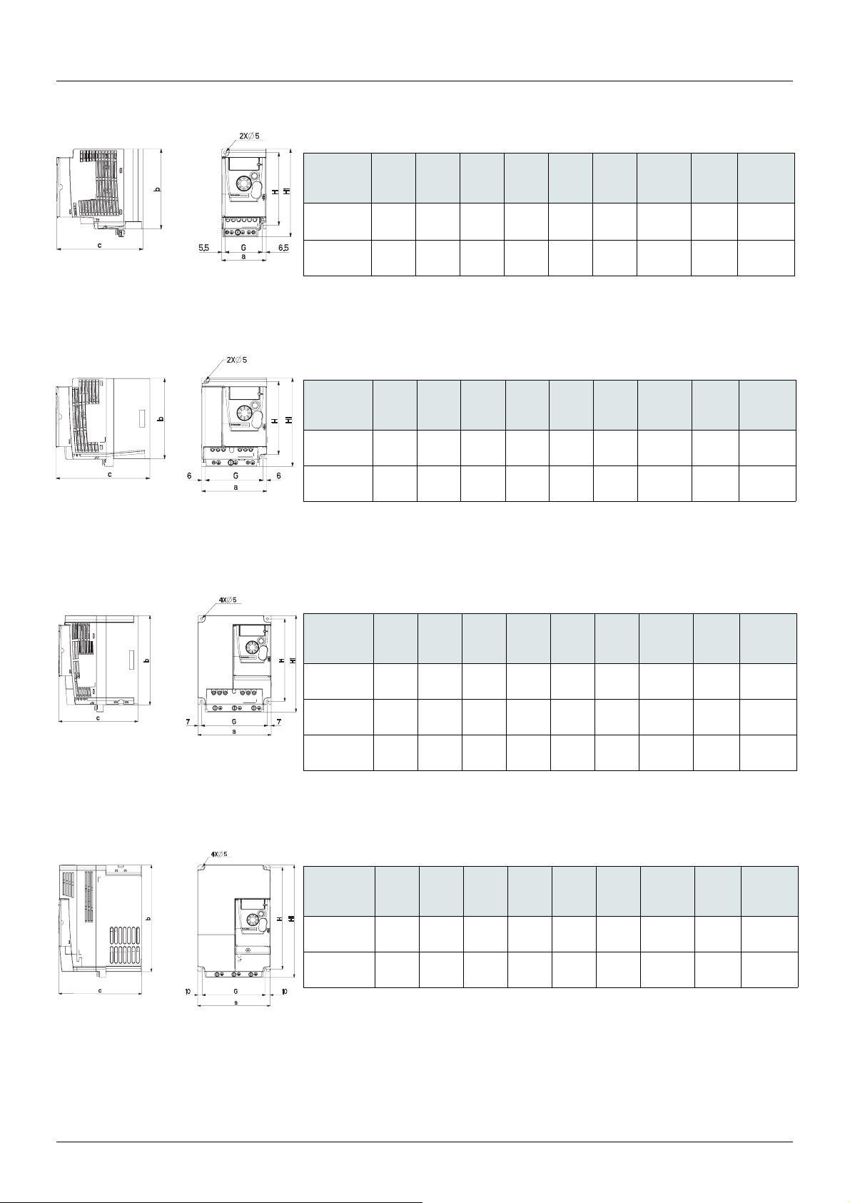
Dimensions and weights
ATV310H037N4p, ATV310H075N4p
ATV310HU15N4p, ATV310HU22N4p
ATV310HU30N4
p, ATV310HU40N4p, ATV310HU55N4p
ATV310H
037N4p
075N4p
ATV310H
U15N4
U22N4
a
mm
(in.)
72
(2.83)
72
(2.83)
mm
(in.)
105
p
(4.13)
105
p
(4.13)
b
mm
(in.)
130
(5.12)
130
(5.12)
a
b
mm
(in.)
130
(5.12)
130
(5.12)
c
mm
(in.)
130
(5.12)60(2.36)
140
(5.51)60(2.36)
mm
(in.)
151
(5.94)93(3.66)
151
(5.94)93(3.66)
G
mm
(in.)
c
G
mm
(in.)
H
mm
(in.)
118
(4.65)
118
(4.65)
H
mm
(in.)
118
(4.65)
118
(4.65)
H1
mm
(in.)
143
(5.63)
143
(5.63)
H1
mm
(in.)
143
(5.63)5(0.20)
143
(5.63)5(0.20)
Ø
mm
(in.)
5
(0.20)
5
(0.20)
Ø
mm
(in.)
For
screws
M4
M4
For
screws
M4
M4
Weight
kg
(lb)
0.8
(1.8)
0.8
(1.8)
Weight
kg
(lb)
1.1
(2.43)
1.1
(2.43)
ATV310HU75N4
p, ATV310HD11N4p
ATV310H
U30N4
U40N4
U55N4
ATV310H
U75N4
D11N4
a
mm
(in.)
140
p
(5.51)
140
p
(5.51)
140
p
(5.51)
mm
(in.)
150
p
(5.91)
150
p
(5.91)
b
mm
(in.)
171
(6.73)
171
(6.73)
171
(6.73)
a
b
mm
(in.)
220
(8.66)
220
(8.66)
c
mm
(in.)
151
(5.94)
151
(5.94)
151
(5.94)
c
mm
(in.)
171
(6.73)
171
(6.73)
G
mm
(in.)
126
(4.96)
126
(4.96)
126
(4.96)
G
mm
(in.)
130
(5.12)
130
(5.12)
H
mm
(in.)
157
(6.18)
157
(6.18)
157
(6.18)
H
mm
(in.)
210
(8.27)
210
(8.27)
H1
mm
(in.)
184
(7.24)5(0.20)
184
(7.24)5(0.20)
184
(7.24)5(0.20)
H1
mm
(in.)
232
(9.13)5(0.20)
232
(9.13)5(0.20)
Ø
mm
(in.)
Ø
mm
(in.)
For
screws
M4
M4
M4
For
screws
M4
M4
Weight
kg
(lb)
1.8
(3.97)
1.8
(3.97)
1.8
(3.97)
Weight
kg
(lb)
3.7
(8.16)
3.7
(8.16)
EAV94277 11/2020 13
Page 14
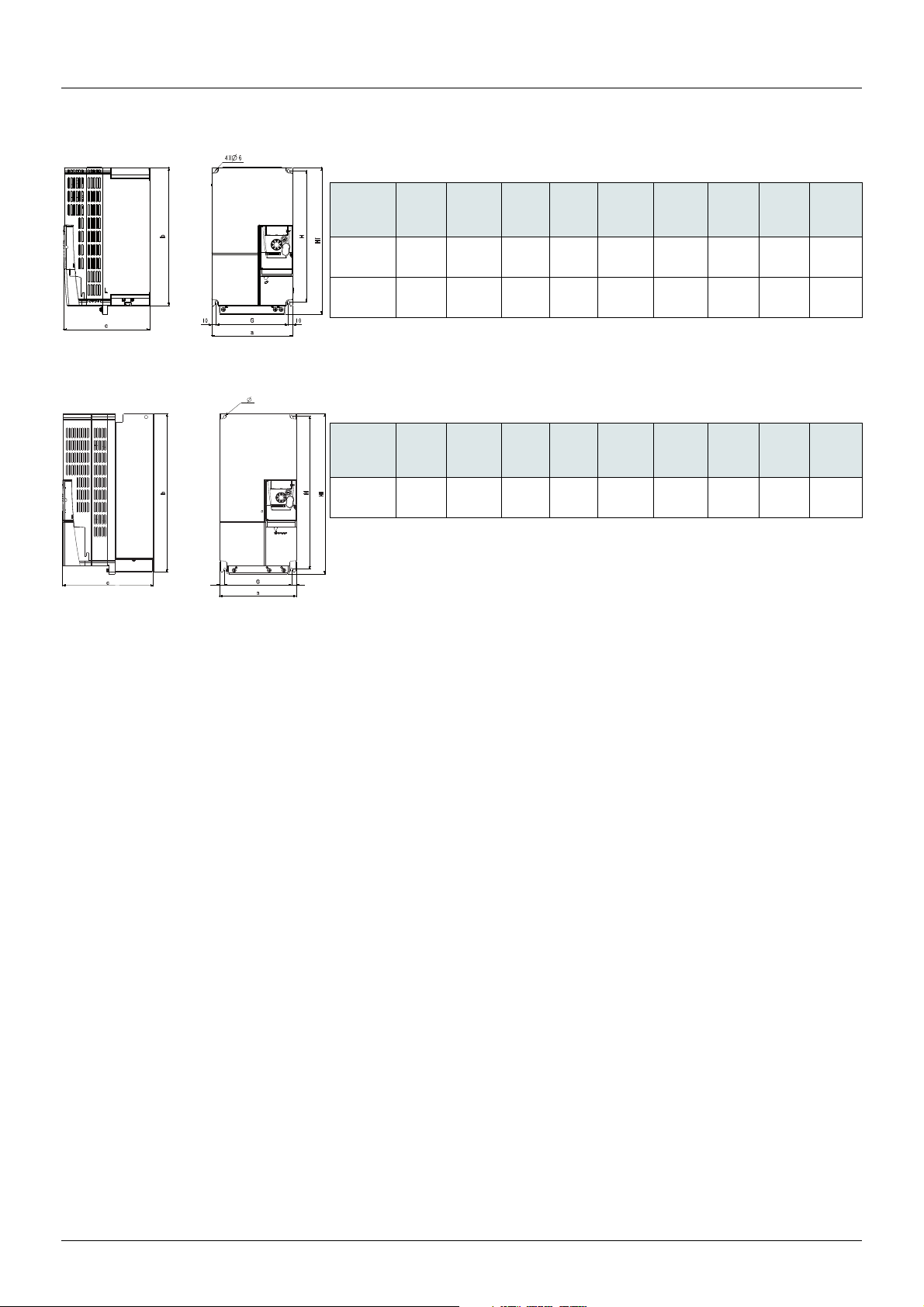
Dimensions and weights
12 12
4X 6
ATV310HD15N4p, ATV310HD18N4p
ATV310HD22N4p
ATV310H
D15N4p
D18N4p
a
mm
(in.)
180
(7.09)
180
(7.09)
b
mm
(in.)
311
(12.24)
311
(12.24)
c
mm
(in.)
191
(7.52)
191
(7.52)
G
mm
(in.)
160
(6.29)
160
(6.29)
H
mm
(in.)
295
(11.61)
295
(11.61)
H1
mm
(in.)
330
(12.99)
330
(12.99)
Ø
mm
(in.)
6
(0.23)
6
(0.23)
screws
Note: for ATV310HD15N4pF and ATV310HD18N4pF, the weight is 6.7kg (14.8Ib).
a
ATV310H
D22N4p
mm
(in.)
180
(7.09)
Note: for ATV310HD22N4
b
mm
(in.)
384.5
(15.14)
c
mm
(in.)
212
(8.35)
pF, the weight is 9.7kg (21.4Ib).
G
mm
(in.)
156
(6.14)
H
mm
(in.)
371.5
(14.63)
H1
mm
(in.)
390
(15.35)
Ø
mm
(in.)
6
(0.23)
screws
For
M5
M5
For
M5
Weight
kg
(lb)
6.3
(13.9)
6.3
(13.9)
Weight
kg
(lb)
8.5
(18.7)
14 EAV94277 11/2020
Page 15

Environmental Conditions
Withstand to harsh environments
• Chemical class 3C3 conforming to IEC/EN 60721
• Mechanical class 3S2 conforming to IEC/EN 60721
Temperature Conditions
Ambient Air Temperature
For HD/ND
(Heavy duty/Normal duty)
Storage All types All types °C -25...70
Operation HD (ATV310H***N4* version) IP20
HD (ATV310H***N4* version) IP4X °C -10...50 without derating
HD (ATV310H***N4* F version) IP20 °C -10...55 without derating
HD (ATV310H***N4* F version) IP20 side by side
ND IP20 °C -10...50 without derating
ND IP20 side by side
Mounting types Temperature
°F -13...158
°C -10...55 without derating
IP20 side by side
IP4X
IP4X
°F 14...131 without derating
°C 55...60 with derating
°F 131...140 with derating
°F 14...122 without derating
°C 50...60 with derating
°F 122...140 with derating
°F 14...131 without derating
°C 55...60 with derating
°F 131...140 with derating
°C -10...50 without derating
°F 14...122 without derating
°C 50...60 with derating
°F 122...140 with derating
°F 14...122 without derating
°C 50...60 with derating
°F 122...140 with derating
°C -10...40 without derating
°F 14...104 without derating
°C 40...60 with derating
°F 104...140 with derating
EAV94277 11/2020 15
Page 16

Environmental Conditions
Relative Humidity
Without dripping water and without condensation: 5...95% according to IEC 60068-2-3
Operating Altitude
Operating altitude Supply voltage Electrical supply network Derating
TT/TN IT Corner-Grounded
m Up to 1000 380 - 460 V three-phase ✔ ✔ ✔ Without derating
ft Up to 3280
m 1000 ... 2000 380 - 460 V three-phase ✔ ✔ ✔ With derating current by 1% (maxi)
ft 3280 ... 6560
m 2000 ... 3000 380 - 460 V three-phase ✔ ✔ - With derating current by 1% (maxi)
ft 6560 ... 9840
Pollution Degree and Degree of Protection
per additional 100 m (328 ft)
per additional 100 m (328 ft
)
Ambient pollution degree according to IEC/EN 61800-5-1:
Pollution Degree Degree of Protection
2 IP20, IP4X with top vent cover.
16 EAV94277 11/2020
Page 17

Mounting
50 mm
(2 in.)
50 mm
(2 in.)
10 mm
(0.4 in.)
Mounting
DANGER
HAZARD OF ELECTRIC SHOCK, EXPLOSION, OR ARC FLASH
• The drive panel must be properly grounded before power is applied.
• Use the provided ground connecting point as shown in the figure below.
Failure to follow these instructions will result in death or serious injury.
DANGER
ATV310HpppN4p - GROUND CONTINUITY HAZARD
An anodized heatsink can create an insulation barrier to the mounting surface. Ensure that you follow the recommended grounding
connections.
Failure to follow these instructions will result in death or serious injury.
DANGER
ELECTRIC SHOCK CAUSED BY FOREIGN OBJECTS OR DAMAGE
Conductive foreign objects in the product or damage may cause parasitic voltage.
• Do not use damaged products.
• Keep foreign objects such as chips, screws or wire clippings from getting into the product.
Failure to follow these instructions will result in death or serious injury.
Install the drive vertically, at ±10°.
Do not place it close to heating elements.
Leave sufficient free space to ensure that the air required for cooling
purposes can circulate from the bottom to the top of the drive.
Free space in front of unit: 10 mm (0.4 in.) minimum.
When IP20 protection is adequate, we recommend that the vent
cover(s) on the top of the drive be removed, as shown below.
We recommend that the drive is installed on a dissipative surface.
Drive installation should employ fastening washers and screws in
combination.
Removing the vent cover
EAV94277 11/2020 17
Page 18
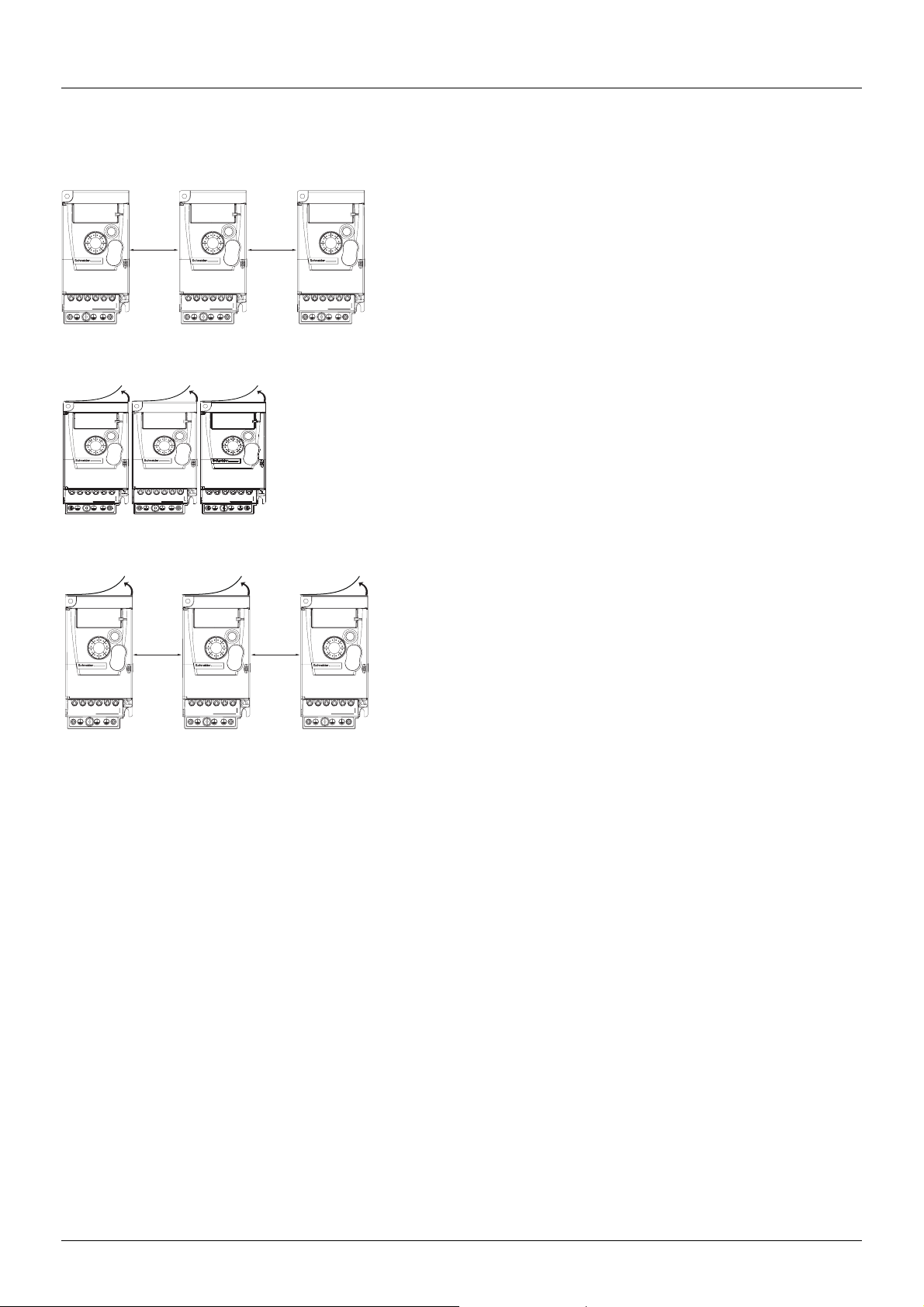
Mounting
Type A mounting
Type A mounting: IP4X
Free space u10 mm (0.4 in.) on each side, with vent cover fitted.
Mounting type A is suitable for drive operation at surrounding air temperatures less
than or equal to 50°C (heavy duty) or 40°C (Normal duty).
When temperature exceeds 50°C (heavy duty) or 40°C (Normal duty), the top vent
cover should be removed to ensure cooling.
10 mm
(0.4 in.)
10 mm
(0.4 in.)
Type B mounting
Type B mounting: side-by-side
Drives mounted side-by-side with vent covers removed. Mounting type B is suitable for drive
operation at surrounding air temperatures less than or equal to 55°C (heavy duty) or 40°C (Normal
duty).
Note: ATV310
N4F operation temperatures less than or equal to 50°C (heavy duty) or 40°C
(Normal duty).
Type C mounting
Type C mounting: IP20
Free space u10 mm (0.4 in.) on each side, without vent cover
Mounting type C is suitable for drive operation at surrounding air temperatures less
than or equal to 55°C (heavy duty) or 50°C (Normal duty).
10 mm
(0.4 in.)
10 mm
(0.4 in.)
Mounting types
With these types of mounting, drives with a Switching frequency range of 4 kHz can be used up to an ambient temperature which was listed
below:
For ATV310
1. At ambient temperatures, IP20/IP20SBS mounting between +55°C and +60°C:
• Derate current by 2.4% for every 1°C of temperature rise
• Switching frequency range will adjust according to the internal temperature of the drive
2. At ambient temperatures, IP4X mounting between +50°C and +60°C:
• Derate current by 6% for every 1°C of temperature rise
• Switching frequency range will adjust according to the internal temperature of the drive
For ATV310
1. At ambient temperatures, IP20 mounting between +50°C and +60°C:
• Derate current by 2.1% for every 1°C of temperature rise
• Switching frequency range will adjust according to the internal temperature of the drive
2. At ambient temperatures, IP20SBS mounting between +40°C and +60°C:
• Derate current by 2.2% for every 1°C of temperature rise
• Switching frequency range will adjust according to the internal temperature of the drive
3. At ambient temperatures, IP4X mounting between +40°C and +60°C:
• Cover top safeguard covers on drives if IP4X
• Derate current by 2% for every 1°C of temperature rise
• Switching frequency range will adjust according to the internal temperature of the drive
18 EAV94277 11/2020
N4 @ Heavy duty
N4 @ Normal duty
Page 19

Mounting
Power dissipated for enclosed drives and required air flow
Drive Overload
HD: Heavy duty
ND: Normal duty
ATV310HU15N4 HD 51.0 14
ATV310HU22N4 HD 65.5 14
ATV310HU30N4 HD 80.2 30
ATV310HU40N4 HD 102.7 30
ATV310HU55N4 HD 141.5 30
ATV310HU75N4 HD 203.9 60
ATV310HD11N4 HD 294.7 60
ATV310HD15N4 HD 438.8 156
ND 508.9 156
ATV310HD18N4 HD 499.6 156
ND 588.0 156
ATV310HD22N4 HD 539.4 128
ND 736.7 128
ATV310HD15N4F HD 447.5 156
ND 517.6 156
ATV310HD18N4FHD 511.9 156
ND 569.8 156
ATV310HD22N4F HD 547.6 128
ND 746.8 128
Power dissipated (W) Minimum air flow rate required per hour (m3/h)
EAV94277 11/2020 19
Page 20
Wiring
General instructions
DANGER
HAZARD OF FIRE OR ELECTRIC SHOCK
• Wire cross sections and tightening torques must comply with the specifications provided in this document
• Do not use multi-conductor cables without cable lugs for any connection with a voltage higher than 25 Vac.
Failure to follow these instructions will result in death or serious injury.
Keep power cables separate from devices containing circuits with low-level signals (detectors, PLCs, measuring apparatus, video, telephone).
Always cross control and power cables at 90° if possible.
Power and circuit protection
Adhere to wire size recommendations contained in local codes and standards.
Before wiring power terminals, connect the ground terminal to the grounding screws located below the output terminals.
The drive must be grounded in accordance with the applicable safety standards.
When upstream protection by means of a residual current device is required by the installation standards, a type A circuit breaker should be
used for single-phase drives and type B for 3-phase drives. Choose a suitable model incorporating:
• High frequency current filtering
• A time delay which prevents tripping caused by the load from stray capacitance on power-up. The time delay is not possible for 30mA
devices.
In this case, choose devices with high interference immunity, such as RCDs with SI type leakage protection.
If the installation includes several drives, provide one "residual current device" per drive.
WARNING
INSUFFICIENT PROTECTION AGAINST OVERCURRENTS
• Properly rated overcurrent protective devices must be used.
• Use the circuit breakers specified in the "Drive ratings" chapter.
• Do not connect the product to a supply mains whose network short-circuit current (ICR) exceeds the permissible value specified in the
"Drive ratings" chapter.
Failure to follow these instructions can result in death, serious injury or equipment damage.
Control
For control and speed reference circuits, we recommend using shielded twisted cables with a pitch of between 25 and 50 mm (1 and 2 in.).
Connect the shielding to ground.
WARNING
UNINTENDED BEHAVIOR OF INPUTS AND OUTPUTS
The functions of the inputs and outputs depend on the selected operating mode and the settings of the corresponding parameters.
• Verify that the wiring is appropriate for the settings.
• Only start the system if there are no persons or obstructions in the zone of operation.
• When commissioning, carefully run tests for all operating states and potential error situations.
Failure to follow these instructions can result in death, serious injury or equipment damage.
Length of motor cables
Please use output filters for shielded motor cable lengths longer than 25 m (82 ft) and unshielded cables longer than 50 m (164 ft).
For accessory part numbers, please refer to the catalogue.
20 EAV94277 11/2020
Page 21
Wiring
Equipment Grounding
Ground the drive according to local and national code requirements. A minimum wire size of 10 mm² may be required to meet standards
limiting leakage current.
DANGER
ELECTRIC SHOCK CAUSED BY INSUFFICIENT GROUNDING
Insufficient grounding causes the hazard of electric shocks.
• Ground the drive system before applying voltage.
• Do not use conduits as protective ground conductors; use a protective ground conductor inside the conduit.
• The cross section of the protective ground conductor must comply with the applicable standards.
• Do not consider cable shields to be protective ground conductors.
Failure to follow these instructions will result in death or serious injury.
DANGER
ATV310HpppN4p - GROUND CONTINUITY HAZARD
An anodized heatsink can create an insulation barrier to the mounting surface. Ensure that you follow the recommended grounding
connections.
Failure to follow these instructions will result in death or serious injury.
DANGER
ELECTRIC SHOCK CAUSED BY INSUFFICIENT GROUNDING
This product has an increased leakage current > 3.5 mA.
• Use a protective ground conductor with at least 10 mm
conductors supplying the power terminals.
• Verify compliance with all local and national electrical code requirements as well as all other applicable regulations with respect to
grounding of all equipment.
Failure to follow these instructions will result in death or serious injury.
2
(AWG 6) or two protective ground conductors with the cross section of the
• Ensure that the resistance of the ground is one ohm or less.
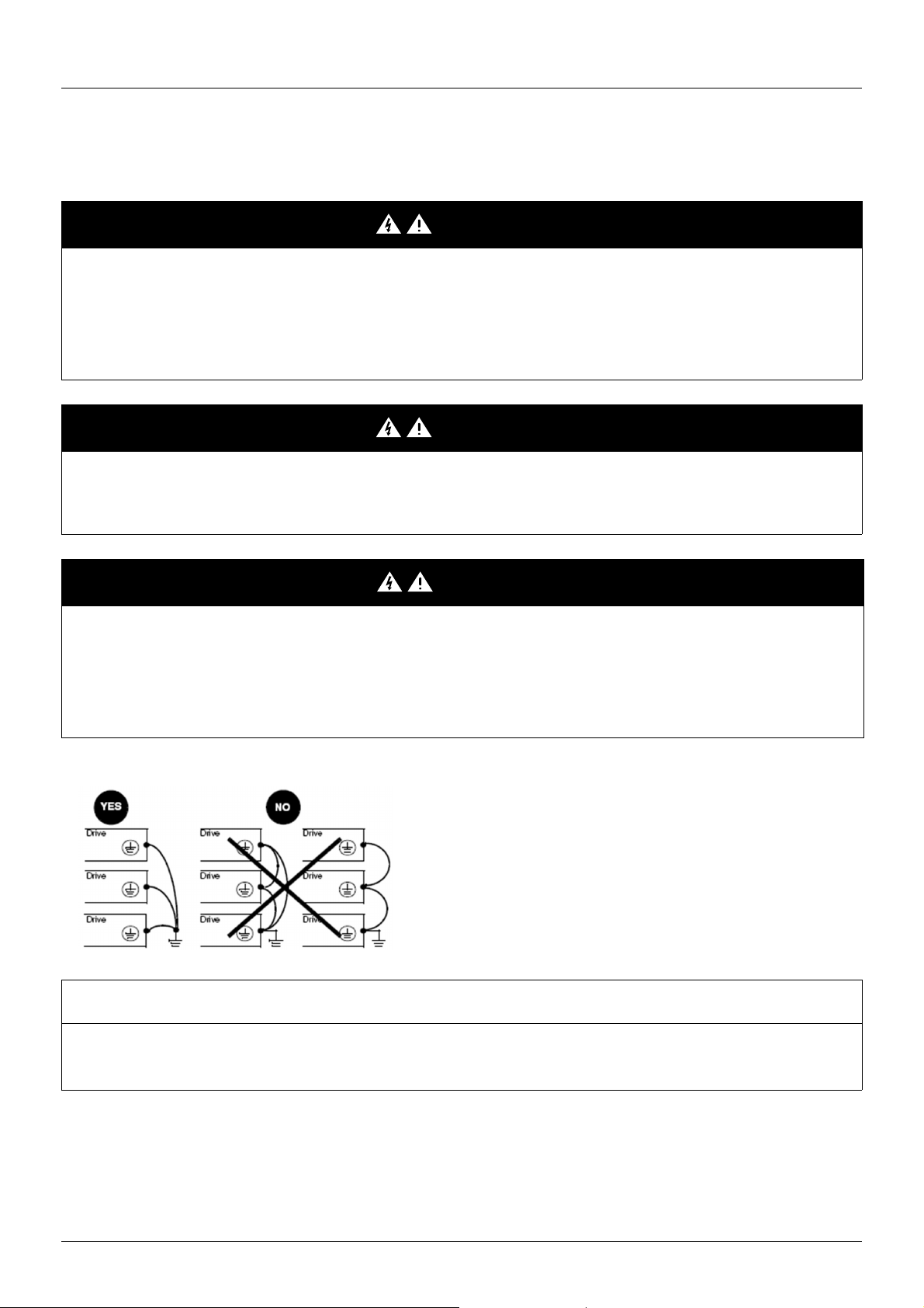
• When grounding several drives, you must connect each one
directly, as shown in the figure to the left.
• Do not loop the ground cables or connect them in series.
NOTICE
DESTRUCTION DUE TO INCORRECT MAINS VOLTAGE
Before switching on and configuring the product, verify that it is approved for the mains voltage.
Failure to follow these instructions can result in equipment damage.
EAV94277 11/2020 21
Page 22

Wiring
WARNING
INSUFFICIENT PROTECTION AGAINST OVERCURRENTS
• Properly rated overcurrent protective devices must be used.
• Do not connect the product to a supply mains whose short-circuit current rating (ICR) exceeds the permissible value (1).
Failure to follow these instructions can result in death, serious injury or equipment damage.
(1) the permisible value of the drive short-circuit current rating is 5kA for product up to 4kW and 22kA above 4kW.
DANGER
HAZARD OF FIRE OR ELECTRIC SHOCK
For drives y 4kW, the length of stripped part of wires connecting motors and drives and connecting to brake resistor should not exceed
10 mm (0.4 in.).
Failure to follow these instructions will result in death or serious injury.
22 EAV94277 11/2020
Page 23

Wiring
U/T1
V/T2
W/T3
PA / +
COM
AI1
+5V
AO1
U1
W1
V1
M
3 a
LI1
LO+
LO-
COM
R1B
R1C
LI2
LI3
LI4
+24 V
PB
R1A
R/L1
S/L2
T/L3
ac
b
3-phase supply 380V...460V
Power
3-phase
motor
Input 380V
Output 380V
General wiring diagram
Wiring label
EAV94277 11/2020 23
Page 24
Wiring
Operation on an IT System
Definition
IT system: Isolated or impedance grounded neutral. Use a permanent insulation monitoring device compatible with nonlinear loads, such as
an XM200 type or equivalent.
Corner grounded system: System with one phase grounded.
Operation
NOTICE
OVERVOLTAGE OR OVERHEATING
If the drive is operated via an IT or corner grounded system, the integrated EMC filter must be disconnected as described in the present
manual.
Failure to follow these instructions can result in equipment damage.
24 EAV94277 11/2020
Page 25

Wiring
Grounding No Grounding
Disconnecting the Built-in EMC Filter
Filter Disconnection
DANGER
HAZARD OF ELECTRIC SHOCK, EXPLOSION OR ARC FLASH
Read and understand the instructions in "Before your begin" chapter before performing any procedure in this chapter.
Failure to follow these instructions will result in death or serious injury.
The drives have a built-in EMC filter (*). As a result, they exhibit leakage current to ground. If the leakage current creates compatibility
problems with your installation (residual current device or other), then you can reduce the leakage current by deactivating the Y capacitors as
shown below. In this configuration the product does not meet the EMC requirements according to the standard IEC 61800-3.
(*): Except ATV310HD
Setting on ATV310HDN4AF/ ATV310HDN4EF drives
Apply the following instructions to set the drive to operate or not on an IT or Corner grounded system
Step Action
1 Remove the power terminal cover
2 The switch is factory set to the position shown on detail
3 To disconnect the built-in EMC filter, remove the screw from its location and set it to the position as shown on detail
4 Refit the front cover
NOTE:
• Use only the screw supplied.
• Do not operate the drive with setting screw removed.
N4A/ ATV310HDN4E drives (for 3-phase 380...460 V supply mains)
EAV94277 11/2020 25
Page 26
Power terminals
DANGER
HAZARD OF ELECTRIC SHOCK, EXPLOSION OR ARC FLASH
Read and understand the instructions in "Before your begin" chapter before performing any procedure in this chapter.
Failure to follow these instructions will result in death or serious injury.
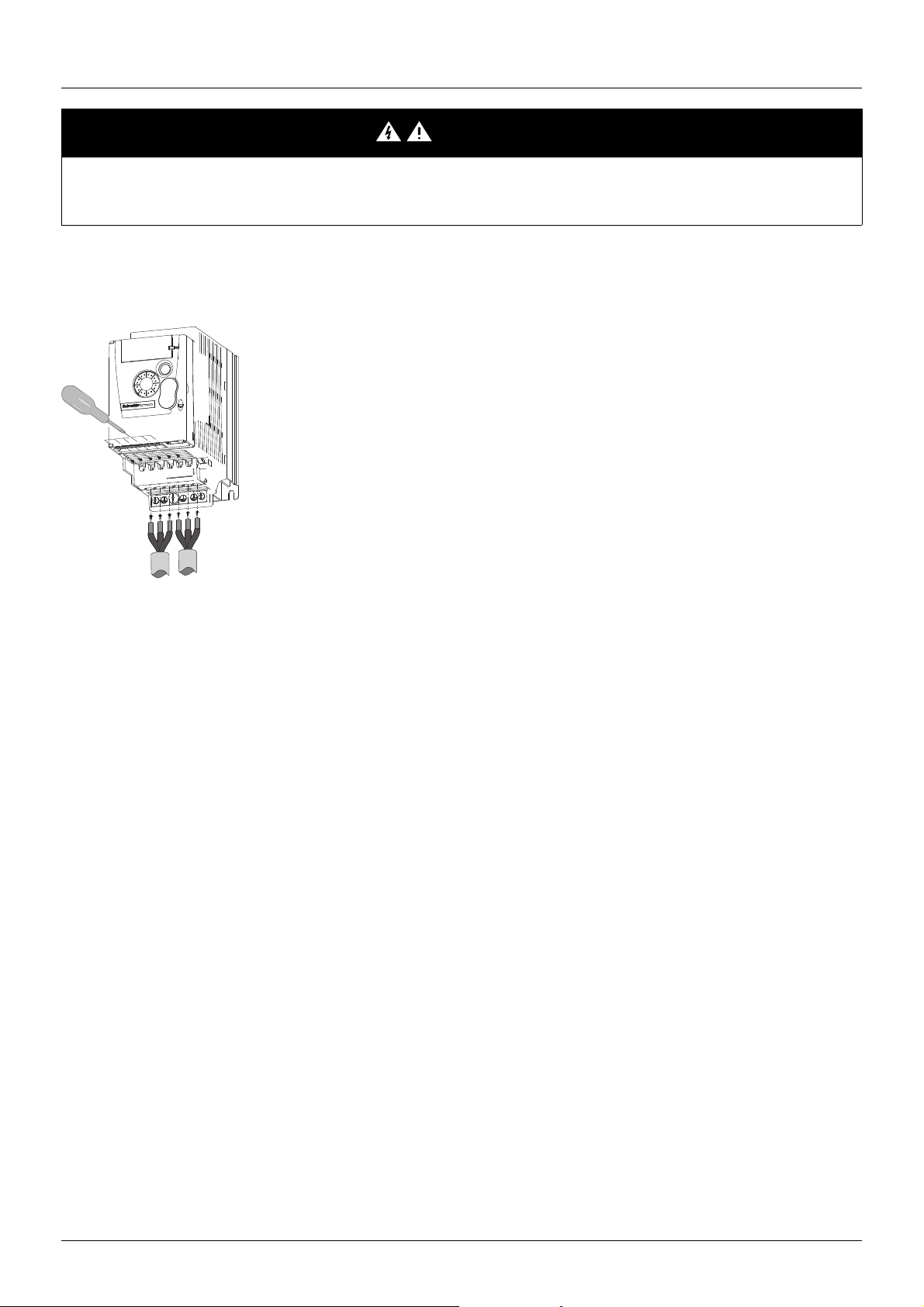
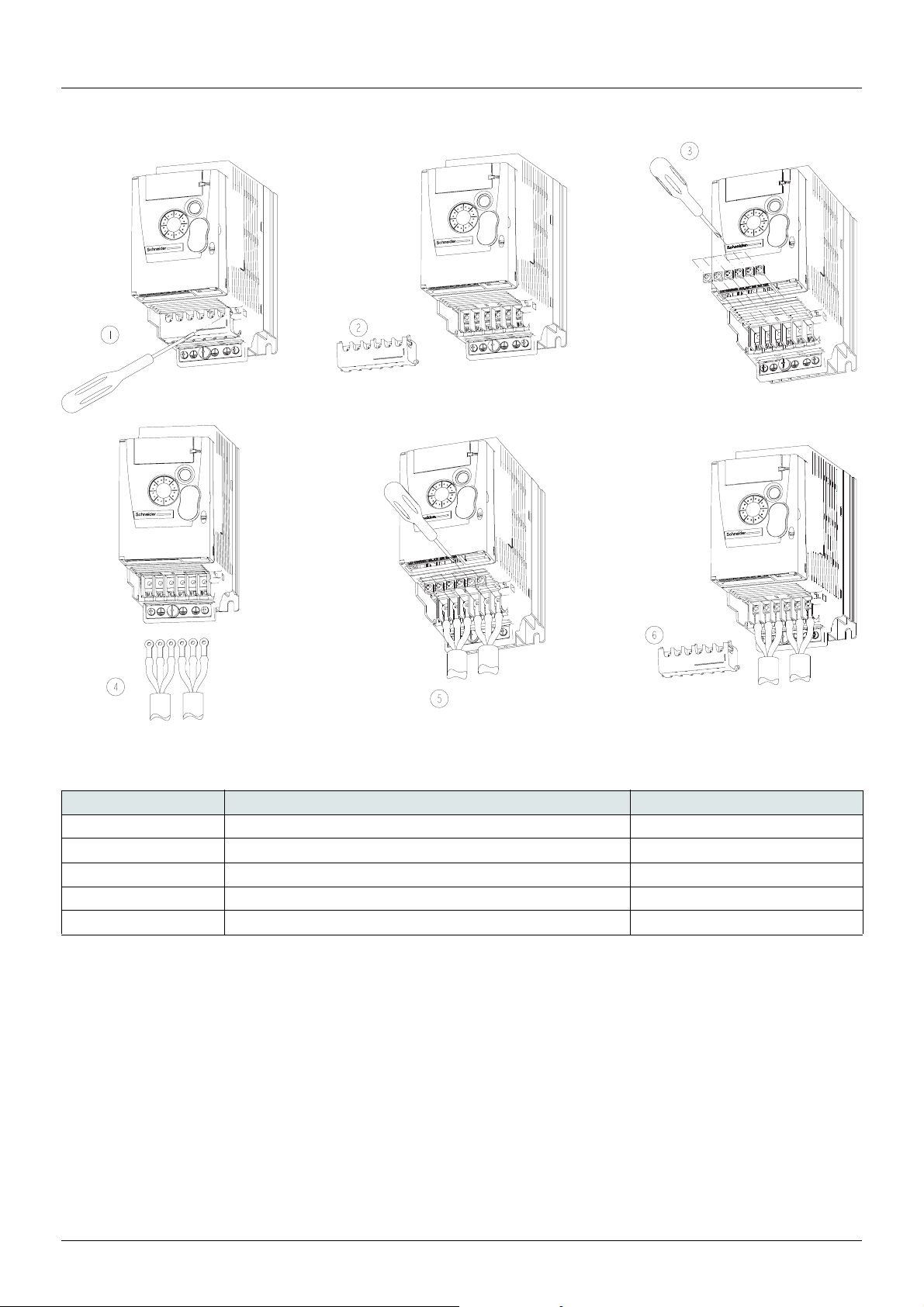
The incoming line power terminals and output terminals to the motor are located at the bottom of the drive. The power terminals can be
accessed without opening the wiring trap if you use stripped wire cables.
Access to the power terminals
Access to the terminals if you use stripped wire cables
26 EAV94277 11/2020
Page 27
Power terminals
Access to the terminals if you use ring terminals
Characteristics and functions of power terminals
Terminal Function For ATV310
t
R/L1 - S/L2 - T/L3 Power input terminal All ratings
PA/+ Brake resistor terminal (DC Bus + output) ATV310HU15N4p...ATV310HD22N4p
PB Brake resistor terminal ATV310HU15N4p...ATV310HD22N4p
U/T1 - V/T2 - W/T3 Motor wiring terminal All ratings
Ground terminal All ratings
EAV94277 11/2020 27
Page 28
Power terminals
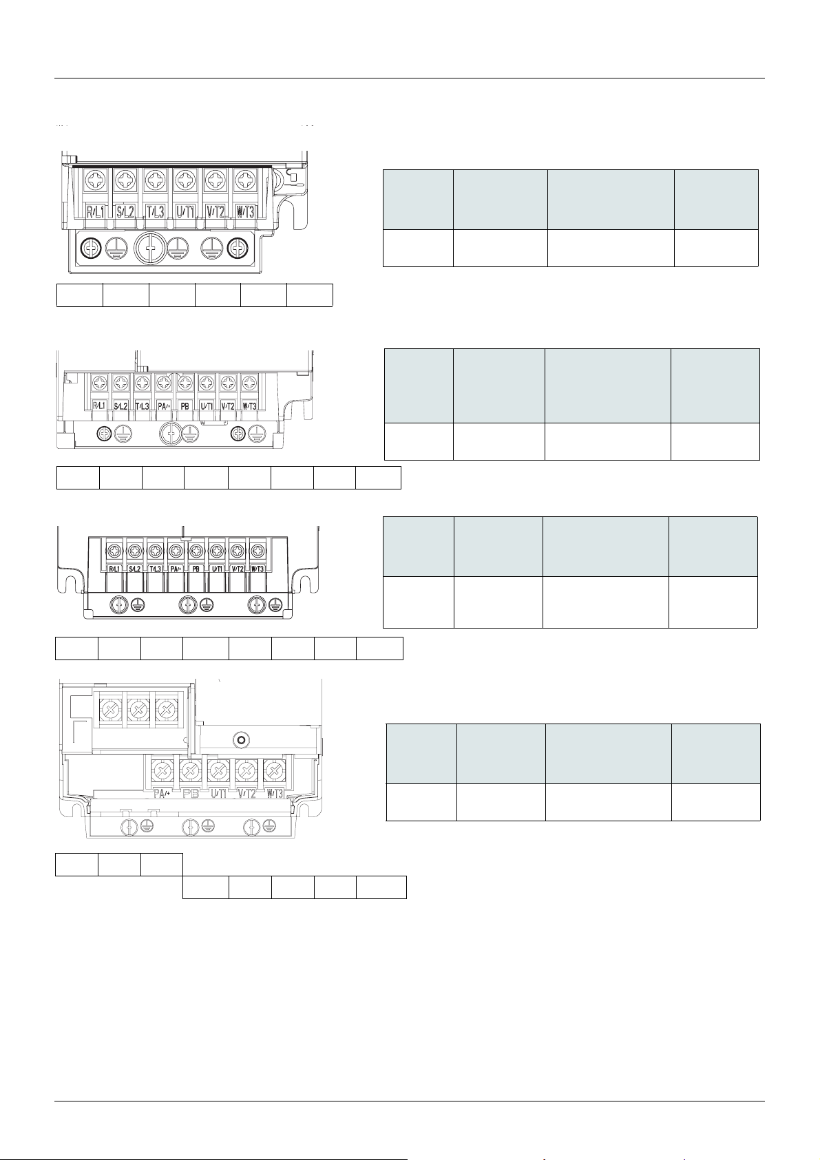
ATV310H
Applicable wire
size (1)
Recommended wire
size (2)
Tightening
torque (3)
mm2 (AWG) mm2 (AWG) N·m (lb.in)
037N4p
075N4p
1.5~2.5 (16~14) 2.5 (14)
0.8~1
(7.1 to 8.9)
(1) The value in bold corresponds to the minimum wire gauge to permit secureness.
(2) 70°C copper cable (minimum wire size for rated use).
(3) Recommended to maximum value.
ATV310H
Applicable
wire size (1)
Recommended wire
size (2)
Tightening
torque (3)
mm2 (AWG) mm2 (AWG)
N·m
(lb.in)
U15N4p
U22N4p
1.5~2.5 (16~14) 2.5 (14)
0.8~1
(7.1 to 8.9)
ATV310H
Applicable
wire size (1)
Recommended wire
size (2)
Tightening
torque (3)
mm2 (AWG) mm2 (AWG) N·m (lb.in)
U30N4p
U40N4p
U55N4p
1.5~4 (16~12)
2.5~4 (14~12)
4 (12)
2.5 (14)
4 (12)
4 (12)
1.2~1.4
(10.6 to 12.4)
ATV310H
Applicable
wire size (1)
Recommended wire
size (2)
Tightening
torque (3)
mm2 (AWG) mm2 (AWG) N·m (lb.in)
U75N4p
D11N4p
6~10 (10~7)
10 (7)
10 (7)
10 (7)
2.2~2.4
(19.5 to 21.2)
R/L1 S/L2 T/L3 U/T1 V/T2 W/T3
R/L1 S/L2 T/L3 PA/+ PB U/T1 V/T2 W/T3
R/L1 S/L2 T/L3 PA/+ PB U/T1 V/T2 W/T3
R/L1 S/L2 T/L3
PA/+ PB U/T1 V/T2 W/T3
Arrangement of the power terminals
Screwdriver(s)
For y11kW terminal wiring, use Phillips-head screwdriver PH2 (Φ6).
28 EAV94277 11/2020
Page 29
Power terminals
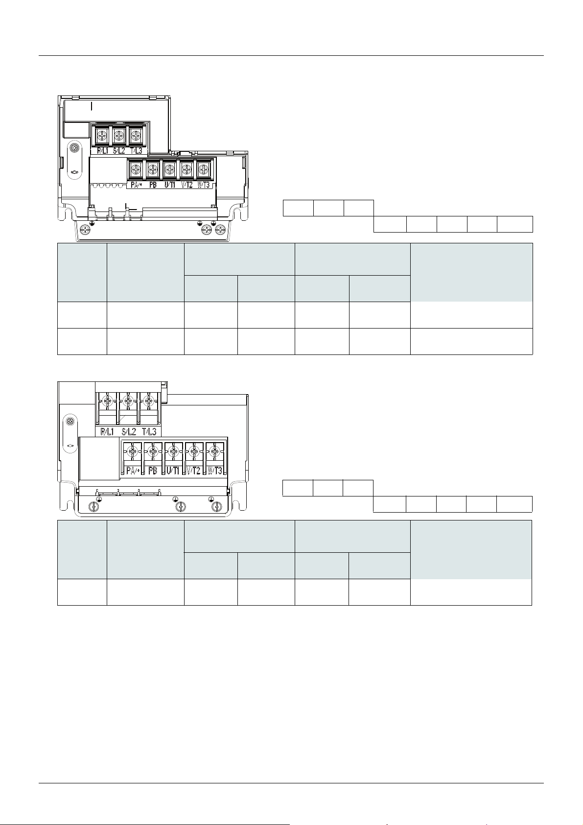
ATV310H
Overload
HD: Heavy duty
ND: Normal duty
Applicable wire size (1) Recommended wire size (2)
Tightening torque (3)
N·m (lb.in)
mm2 (AWG) mm2 (AWG)
Supply
terminals
Output
terminals
Supply
terminals
Output
terminals
D15N4p
HD
ND
16~25(4~3)
16~25(4~3)
10~25(6~3)
10~25(6~3)
25(3)
25(3)
16(4)
16(4)
2.2~2.4 (19.5 to 21.2)
D18N4p
HD
ND
25(3)
16~25(4~3)
10~25(6~3)
16~25(4~3)
25(3)
25(3)
16(4)
16(4)
2.2~2.4 (19.5 to 21.2)
(1) The value in bold corresponds to the minimum wire gauge to permit secureness.
(2) 70°C copper cable (minimum wire size for rated use).
(3) Recommended to maximum value.
R/L1 S/L2 T/L3
PA/+ PB U/T1 V/T2 W/T3
ATV310H
Overload
HD: Heavy duty
ND: Normal duty
Applicable wire size (1) Recommended wire size (2)
Tightening torque (3)
N·m (lb.in)
mm2 (AWG) mm2 (AWG)
Supply
terminals
Output
terminals
Supply
terminals
Output
terminals
D22N4p
HD
ND
35(2)
25~35(3~2)
16~35(4~2)
25~35(3~2)
35(2)
35(2)
25(3)
25(3)
4.5~5.0 (39~43.4)
R/L1 S/L2 T/L3
PA/+ PB U/T1 V/T2 W/T3
Arrangement of the power terminals
Screwdriver(s)
For 15kW and 18.5kW terminal wiring, use Phillips-head screwdriver PH2 (Φ6).
For 22kW terminal wiring, use Phillips-head screwdriver PH3 (Φ8).
EAV94277 11/2020 29
Page 30

Power terminals
F
E
Wire
Heat shrink tube
B
A
d2
w
C
Ring Plug
Figure 1
Figure 2
d1
The specification of main circuit terminal
• Ring lug is required for main circuit terminal connection, please refer to Figure 1 for the specifications of the ring lug.
• Wire should be crimped into UL compliant ring lug before putting on the insulated heat shrink tube, which is UL and CSA compliant,
600Vac voltage withstand, YUPU2, please refer to Figure 2 for the specifications of the heat shrink tube.
Ring lug size table:
Rated Output
Power (kW)
15 16~25
18.5 16~25
22 25~35
Input Cable
Cross -section
(mm
(AWG6~4)
(AWG6~4)
(AWG3~2)
Motor Cable
)
Cross -section
2
(mm
)
10~25
(AWG6~3)
10~25
(AWG6~3)
16~35
(AWG4~2)
2
A
(MAX)B(MAX)C(MIN)
33 10 12 Depend on cable 5.2 13 10~14 13
33 10 12 Depend on cable 5.2 13 10~14 13
33 8 12 Depend on cable 6.2 13 10~14 16
d1 d2
(MIN)E(MIN)F(Range
)
W
(MAX)
30 EAV94277 11/2020
Page 31

Control terminals
It is possible to lock the
cover with a lead seal.
R1A
R1B
R1C
COM
AI1
5V
AO1
LO+
LO-
COM
LI1
LI2
LI3
LI4
R1A
R1B
R1C
COM
AI1
5V
AO1
LO+
LOCOM
LI1
LI2
LI3
LI4
+24V
RJ45
RJ45
(1) The value in bold corresponds to the minimum wire gauge to permit secureness.
(2) Recommended to maximum value.
ATV310 Control
terminals
Applicable wire size (1) Tightening torque (2)
mm2 (AWG) N·m (lb.in)
R1A, R1B, R1C 0.75 to 1.5 (18 to 16)
0.5 to 0.6 (4.4 to 5.3)
Other terminals 0.14 to 1.5 (26 to 16)
Normally open (NO) contact of the relay
Normally closed (NC) contact of the relay
Common pin of the relay
COMmon of analog and logic I/Os
Analog Input
+5VDC supply provided by the drive
Analog Output
Logic Output (collector)
Common of the logic Output (emitter)
COMmon of analog and logic I/Os
Logic Input
Logic Input
Logic Input
Logic Input
+24 VDC supply provided by the drive
Modbus network or remote display panel interface.
Keep the control circuits away from the power cables. For control and speed reference circuits, we recommend using shielded twisted cables
with a pitch of between 25 and 50mm (1 and 2 in.). Connect the shield to ground as outlined on page
Access to the control terminals
To access the control terminals, open the cover.
Note: For information regarding HMI button functions, see "HMI description" on page 39
.
35.
Arrangement of control terminals
Recommended screwdriver(s)
Control terminal wiring requires a Phillips-head screwdriver PH0 (Φ3).
EAV94277 11/2020 31
Page 32

Control terminals
AI1 Com
+24V
AI1 Com
+24V
ATV310 ATV310
(1)
(1)
Characteristics and functions of the control terminals
Terminal Function Electrical characteristics
R1A NO contact of the relay Minimum switching capacity:
• 5mA for 24 V
R1B NC contact of the relay
Maximum switching capacity:
• on inductive load (cos = 0.4 and L/R = 7 ms):
R1C Common pin of the relay
2A for 250V
• on resistive load (cos = 1 and L/R = 0):
3A for 250V
• response time: 30ms maximum.
COM Common of analog and logic I/Os
AI1 Voltage or current
analog input
• resolution: 10 bits
• precision: ± 1% at 25°C (77°F)
• linearity: ± 0.3% (of full scale)
• sampling time: 20 ms ± 1 ms
Analog voltage input 0 to +5 V or 0 to + 10 V
(maximum voltage 30 V) impedance: 30 k
Analog current input x to y mA, impedance: 250
LIU Logic input plus • When the inverter is positive logic, AI1 can be used as a logic input by setting the AI1 type to LIU.
• When the inverter is negative logic, by setting the AI1 type to LIU, plus the AI1 pull-up resistor, AI1
can be used as a logic input.
• When AI1 is used as a logic input, the input impedance is 30k;
Internal power supply or external power supply, the maximum input voltage of AI1 port is 20 V
- if ≤3 V, state 0
- if ≥7 V, state 1
c
a and 30V c
a, 4A for 30V c
Source Sink
(1) The series resistance is 15k
5V Power supply for
reference potentiometer
AO1 Voltage or current
analog output
• precision: ± 5%
• maximum current: 10 mA
• resolution: 8 bits
• precision: ± 1% at 25°C (77°F)
• linearity: ± 0.3% (of full scale)
• sampling time: 4 ms (max. 7 ms)
Analog voltage output: 0 to +10 V (maximum voltage +1%)
• minimum output impedance: 470
Analog current output: x to 20 mA
• maximum output impedance: 800
LO+ Logic output • voltage: 24 V (maximum 30 V)
• impedance: 1 k, maximum 10 mA (100 mA in open collector)
• linearity: ± 1%
• sampling time: 20 ms ± 1 ms.
LO- Common of the logic output (emitter)
LI1
LI2
LI3
LI4
Logic inputs Programmable logic inputs
• +24 VDC power supply (maximum 30 V)
• impedance: 3.5 k
• state: 0 if < 5 V, state 1 if > 11 V in positive logic
• state: 1 if < 10 V, state 0 if > 16 V or switched off (not connected)
in negative logic
• sampling time: < 20 ms ± 1 ms.
+24V +24 VDC supply provided
by the drive
+24 VDC -15% +20% protected against short-circuits and overloads.
Maximum customer current available: 100 mA
32 EAV 94277 11/2020
Page 33

Control terminals
Pin Signal
1
2
3
4 D1 (1)
5 D0 (1)
6
7VP (2)
8 Common (1)
(1) Modbus signals
(2) Supply for RS232 / RS485 converter or a remote terminal
D0,D1
信号及
Com
都需接
D0,D1signal and Com
દڽବԈܶԧ
all need connection
(Refer to quick start guide)
Shield - Common
8........................1
Modbus Connection (RJ45)
EAV94277 11/2020 33
Page 34
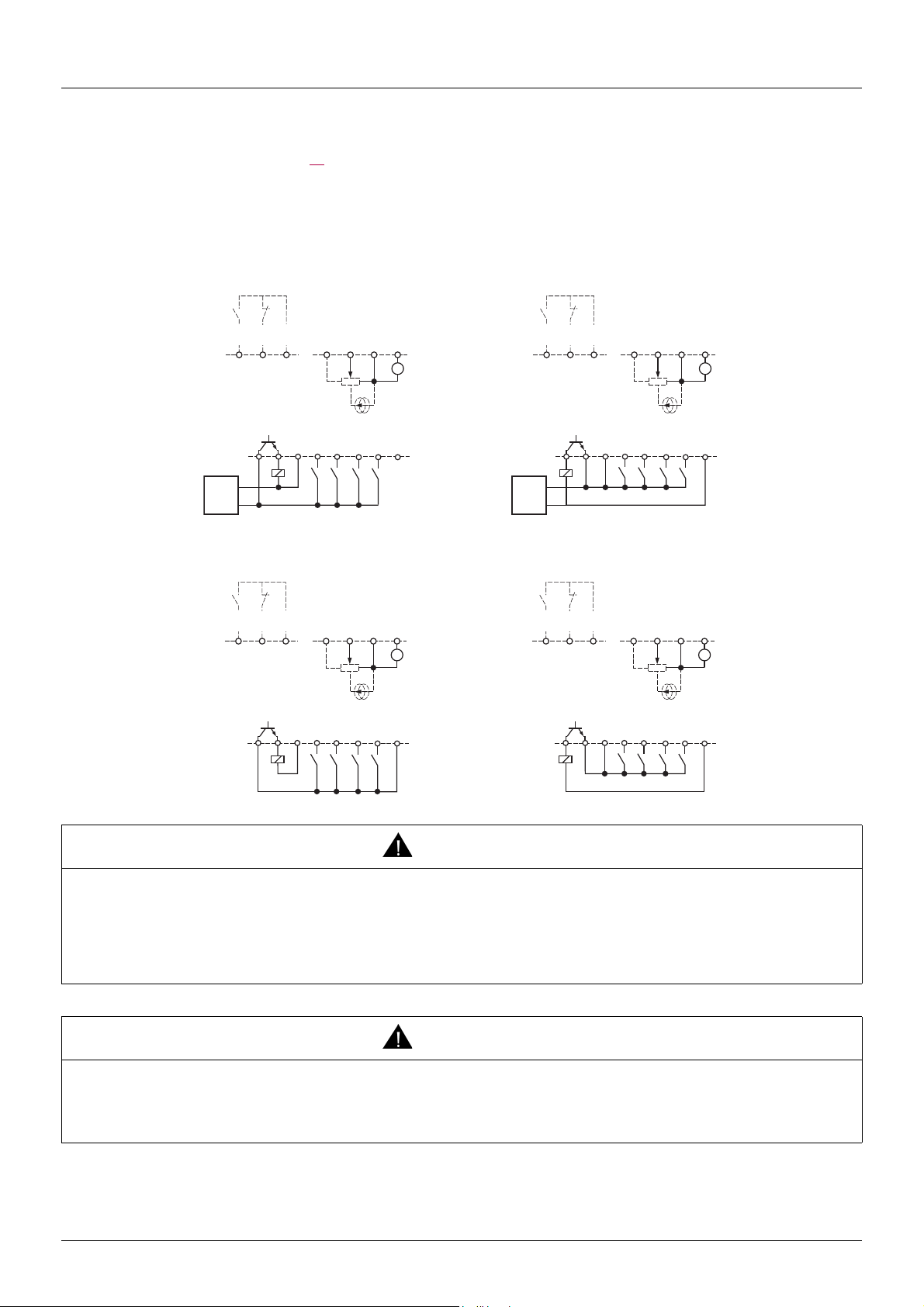
Control terminals
+24V
COM
LI1
LI3
LI2
LI4
COM
AI1
5V
AO1
G
R1A
R1B
R1C
LO-
LO+
+24V
COM
LI1
LI3
LI2
LI4
COM
AI1
5V
AO1
G
R1A
R1B
R1C
LO-
LO+
Source - using external supply Sink - using external supply
Source - using internal supply Sink - using internal supply
Control connection diagrams
Logic inputs type 203 parameter (page 59) is used to adapt the operation of the logic inputs to the technology of the programmable
controller outputs.
• Set the parameter to 00 for Source operation.
• Set the parameter to 01 for internal Sink operation.
• Set the paramters to 02 for external Sink operation.
Note: The modification will be taken into account only at the next control power-on.
0 V
+24 V
R1A
R1B
LO+
LO-
R1C
COM
LI1
5V
AI1
LI2
LI3
COM
LI4
AO1
G
+24V
0 V
+24 V
R1A
R1B
LO+
LO-
R1C
COM
LI1
5V
AI1
LI2
LI3
COM
LI4
AO1
G
+24V
WARNING
UNANTICIPATED EQUIPMENT OPERATION
• If the function Logic input type 203 is set to "01" or "02", do not connect the "O V" terminal to ground or to protective ground.
• Verify that accidental grounding of digital inputs configured for sink logic, caused, for example, by damage to the signal cables, cannot
occur.
• Follow all applicable standards and directives such as NFPA 79 and EN 60204 for proper control circuit grounding practices.
Failure to follow these instructions can result in death, serious injury or equipment damage.
WARNING
UNANTICIPATED EQUIPMENT OPERATION
• Do not used a PLC to command the logic input of the drive in sink mode.
• If this behaviour is required, contact Schneider Office for additional information.
Failure to follow these instructions can result in death, serious injury or equipment damage.
34 EAV94277 11/2020
Page 35
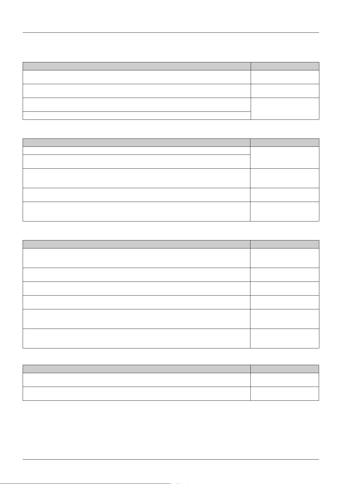
Electromagnetic Compatibility
Electromagnetic Compatibility (EMC), Wiring
EMC requirements for the control cabinet
EMC measures Objective
Use mounting plates with good electrical conductivity, connect large surface areas of metal parts, remove paint
from contact areas.
Ground the control cabinet, the control cabinet door and the mounting plate with ground straps or ground wires.
The conductor cross section must be at least 10 mm
Fit switching devices such as power contactors, relays or solenoid valves with interference suppression units or arc
suppressors (for example, diodes, varistors, RC circuits).
Install power components and control components separately.
2
(AWG 8).
Shielded cables
EMC measures Objective
Connect large surface areas of cable shields, use cable clamps and ground straps. Reduces emissions.
Use cable clamps to connect a large surface area of the shields of all shielded cables to the mounting plate at the
control cabinet entry.
Ground shields of digital signal wires at both ends by connecting them to a large surface area or via conductive
connector housings
Ground the shields of analog signal wires directly at the device (signal input); insulate the shield at the other cable
end or ground it via a capacitor (for example, 10 nF, 100 V or higher.
Use only shielded motor cables with copper braid and a coverage of at least 85%, ground a large surface area of
the shield at both ends.
Good conductivity due to large
surface contact.
Reduces emissions.
Reduces mutual interference.
Reduces interference affecting
the signal wires, reduces
emissions
Reduces ground loops due to
low-frequency interference.
Diverts interference currents in a
controlled way, reduces
emissions.
Cable Installation
EMC measures Objective
Do not route fieldbus cables and signal wires in a single cable duct together with lines with DC and AC voltages of
more than 60 V. (Fieldbus cables, signal lines and analog lines may be in the same cable duct)
Recommendation: Use separate cable ducts at least 20 cm apart.
Keep cables as short as possible. Do not install unnecessary cable loops, use short cables from the central
grounding point in the control cabinet to the external ground connection.
Use equipotential bonding conductors in the following cases: wide-area installations, different voltage supplies
and installation across several buildings.
Use fine stranded equipotential bonding conductors. Diverts high-frequency
If motor and machine are not conductively connected, for example by an insulated flange or a connection without
surface contact, you must ground the motor with a ground strap or a ground wire. The conductor cross section
must be at least 10 mm2 (AWG 6).
Use twisted pair for the DC supply.
For digital and analog inputs use shielded twisted cables with a pitch of between 25...50 mm (1...2 in).
Reduces mutual interference.
Reduces capacitive and
inductive interference.
Reduces current in the cable
shield, reduces emissions.
interference currents
Reduces emissions, increases
immunity.
Reduces interference affecting
the signal cables, reduces
emissions.
Power Supply
EMC measures Objective
Operate product on mains with grounded neutral point. Enables effectiveness of mains
filter.
Surge arrester if there is a risk of overvoltage. Reduces the risk of damage
caused by overvoltage.
EAV94277 11/2020 35
Page 36
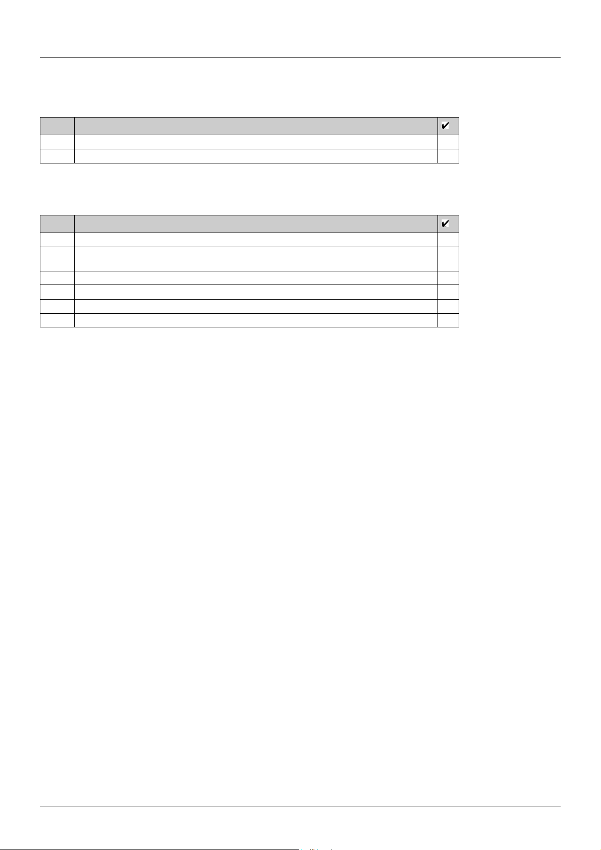
Check list Before Switching On
Mechanical Installation
Verify the mechanical installation of the entire drive system:
Step Action
1 Does the installation meet the specified distance requirements?
2 Did you tighten all fastening screws with the specified tightening torque?
Electrical installation
Verify the electrical connections and the cabling:
Step Action
1 Did you connect all protective ground conductors?
2 Does circuit breaker has the correct rating refer to page (tableau ajouté en Safety page 10, dans les
drive ratings).
3 Did you connect or insulate all wires at the cable ends?
4 Did you properly connect and install all cables and connectors?
5 Do all plug-in terminals colors and markings correspond to the colo rs and marking of the control block?
6 Did you properly connect the signal wires?
Covers And Seals
Verify that all covers and seals of the control cabinet are properly installed to meet the required degree of protection.
36 EAV94277 11/2020
Page 37
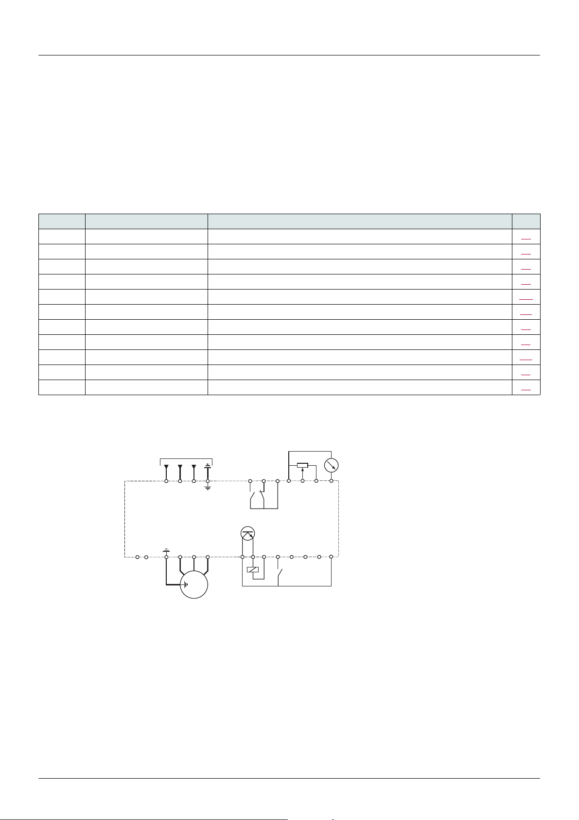
Factory configuration
ATV310ppppN4p
3-phase
motor
Source
Drive factory settings
The ATV310 is factory-set for the most common operating conditions (motor rating according to drive rating):
• Display: drive ready (--00) with motor stopped or motor frequency reference while running
• Automatic adaptation of the deceleration ramp in the event of overvoltage on braking
• No automatic restarting after a detected fault is cleared
• Logic inputs:
-LI1: forward (2-wire transitional control)
- LI2, LI3, LI4: no assignment
• Logic output: LO1: no assignment
• Analog input: AI1 (0 to + 5 V) speed reference
• Relay R1: fault as default setting. R1A opens and R1B closes when a fault is detected or no line voltage is present.
• Analog output AO1: no assignment
Code Description Value Page
301 Standard motor frequency 50 Hz 65
304 Rated motor voltage 380V 65
501.0 Acceleration 3 s 74
501.1 Deceleration 3 s 74
512.0 Low speed 0 Hz 100
512.2 High speed 50 Hz 101
309 Motor control type Standard U/F law 66
310 IR compensation 100% 67
604.0 Motor thermal current equal to nominal motor current (value determined by drive rating) 105
504.1 Automatic DC injection current 0.7 x rated drive current, for 0.5 seconds. 79
315 Switching frequency 4 kHz 68
If the above values are compatible with the application, the drive can be used without changing the settings.
Drive factory wiring diagram
(1) R1 relay contacts, for remote indication of the drive status.
(2) Internal + 24 V
+ 24 V
(3) Reference potentiometer SZ1RV1202 (2.2 k
(4) Forward.
c. I f an ext ernal s ource is used (+ 30 V c maximum), connect the 0 V of the source to the COM terminal, and do not use the
c terminal on the drive.
PA / +
PB
R/L1
(1) (3)
R1A
T/L3
S/L2
LO+
U/T1
V/T2
W/T3
V1
U1
W1
M
3 a
) or similar (10 k maximum).
LO-
R1B
COM
R1C
(4)
LI1
ac
b
AI1
COM
LI2
LI3
+5V
LI4
AO1
(2)
+24 V
EAV94277 11/2020 37
Page 38

Basic functions
Status relay, unlocking
The R1 status relay is energized when the drive power is applied with no fault detected. It de-energizes in the event of a detected fault or when
the drive power is removed.
The drive is reset after a detected fault:
• by switching off the drive until the display disappears completely, then switching on again.
• automatically when "automatic restart" function is enabled, fault detection me nu 600-, Automatic restart 602.0 parameter (page
102) set to 01.
• via a logic input when this input is assigned to the "drive reset" function, fault detection menu 600- menu, Detected fault reset
assignment 601 (page 102) set to LpH.
• by using the "run" key on the drive to reset section fault. See Reset all previous detected faults via Run key 614 parameter (page 108).
Drive thermal detection
Thermal detection is provided by a built-in PTC probe in the power module.
Drive ventilation
Ratings up to 0.75 kW (1 HP) do not include a fan. Other ratings do contain a built-in cooling fan. There are two cooling fan run modes: in the
first, the fan runs when drive is running; in the second, the fan runs when the drive thermal state requires ventilation. The fan runs only runs
when the drive thermal state requires ventilation.
Motor thermal detection
Function:
Thermal detection by calculating the I2t.
Note: The motor thermal state memo returns to zero when the drive power is cycled if Motor thermal state memo 604.3 parameter (page
105
) is not set to 01.
NOTICE
MOTOR OVERHEATING
The motor thermal state is not saved when drive is switched off.
When the drive is switched on, it is not aware of the thermal state of the connected motor or motors.
To enable correct temperature monitoring of the motors, install an external temperature sensor for each motor.
Failure to follow these instructions can result in equipment damage.
NOTICE
MOTOR OVERHEATING
Install external thermal monitoring equipment under the following conditions:
• If a motor with a nominal current of less than 20% of the nominal current of the drive is connected.
• If you use the function Motor Switching.
• If several motors are connected to the same drive
Failure to follow these instructions can result in equipment damage.
38 EAV94277 11/2020
Page 39
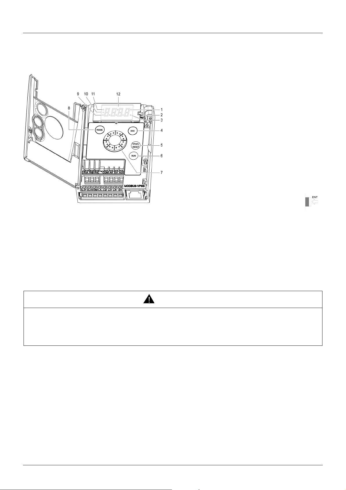
Programming
HMI description
Functions of the display and keys
1. Value LED (a) (b)
2. Charge LED
3. Unit LED (c)
4. ESC button: Exits a menu or parameter, or aborts the displayed
value to return to the previous value in the memory. In LOCAL
configuration, a 2 s press on ESC button switches between the
control/programming modes.
Note: In LOCAL configuration, the three Leds 9, 10, 11 are blinking
simultaneously in programming mode and are working as a Led
chaser in control mode.
5. STOP/RESET button: stops the motor (could be hidden by door if
function disabled). Important: See instructions for "RUN/STOP"
cover removal.
6. RUN button: Starts running in LOCAL configuration and in
REMOTE configuration if the function is configured (could be
hidden by door if function disabled).
7. Jog Dial
- Acts as a potentiometer in local mode in LOCAL configuration
and in REMOTE configuration if the function is configured
- For navigation when turned clockwise or counterclockwise
- And selection / validation when pushed
This action is represented by the symbol on the right.
8. MODE button
Switches between the control/programming modes. A 3 s press
on MODE button switches between the REMOTE/LOCAL
configurations.
9. CONFIGURATION mode LED (b)
10. MONITORING mode LED
11. REFERENCE mode LED
12. Four "7-segment" displays
Note: In LOCAL configuration, the three Leds 9, 10, 11 are blinking simultaneously in programming mode and are working as a Led chaser in
control mode.
(a) If illuminated, indicates that a value is displayed, for example, 0.5 is displayed for “0.5”.
(b) When changing a value the Configuration mode LED and the value LED are on steady.
(c) If illuminated, indicates that a unit is displayed, for example, AMP is displayed for “Amps”.
WARNING
LOSS OF CONTROL
The function Stop key priority 405 parameter disables the Stop keys of the drive and of the Remote Display Terminal if the setting of
the parameter is 00.
Only set this parameter to 00 if you have implemented appropriate alternative stop functions.
Failure to follow these instructions can result in death, serious injury or equipment damage.
EAV94277 11/2020 39
Page 40

Programming
Remote control
Remote operation and programming by HMI is possible using the optional display terminal part VW3A1006. The dimensions of the display
terminal part are 70 mm (2.76 in) x 50 mm (2.76 in).
Note: Set the remote display terminal with:
- Modbus rate = 19.2 Kbps, (see 702, page 109
- Modbus format = 8E1, 8 bit, even parity, 1 stop bit (see 703, page 109
)
).
40 EAV94277 11/2020
Page 41
Programming
COnF
rEF
--12
--00
--13
800
3s
MODE
3s
MODE
2s
ESC
--00
ESC ENT
ESCESC
ESC
MODE MODE MODE
--00
Remote Mode
Local Mode
Actual Frequency
SPEED REFERENCE
MONITORING
CONFIGURATION
First power-up
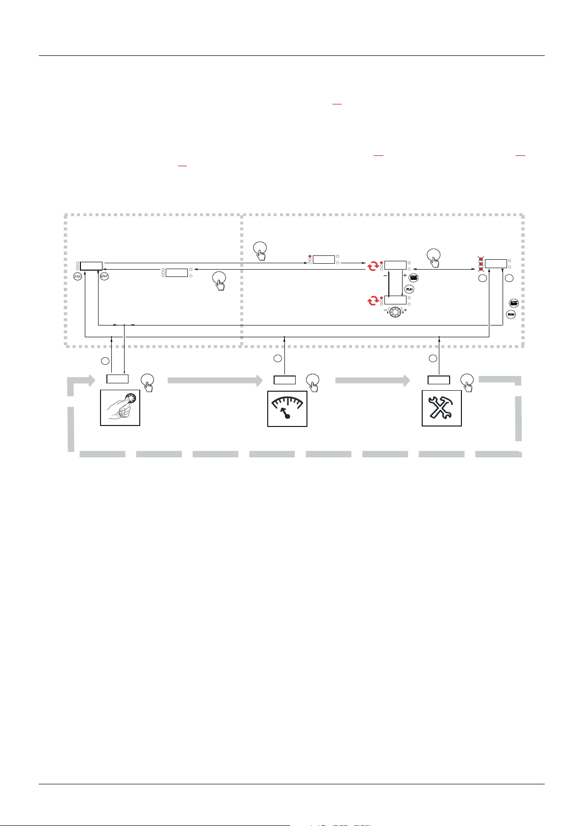
At first power-up you are prompted to set Standard motor frequency 301 (page 65). Next time power is applied --00 appears. Operating
mode selection is then possible using the MODE or JOG key as detailed below.
Menus structure
Access to menus and parameters is possible through the Reference (rEF) mode (page 46), Monitoring (800-) mode (page 46) and
Configuration (COnF) mode (page 52
keyboard. The first MODE key depression moves from current position to the top of the branch. A second depression switches to next mode.
). Switching between these modes is possible at any time using the MODE key or Jog Dial on the
EAV94277 11/2020 41
Page 42

Structure of parameter tables
3
4
1
5
8
2
7
6
9
10
1. Name of mode
2. Name of section, if any
3. Menu code on 4-digit 7-segment display, followed by a "-"
4. Sub-menu code on 4-digit 7-segment display, if any
5. Parameter code
6. Value code
7. Name of menu
8. Name of sub-menu
9. Parameter description
10. Possible value(s) / state of parameter, if any
The mode, sectional, menu, sub-menu and parameter table structure is laid out below.
Note: Parameters containing the sign
Example:
Configuration Mode - Complete menu (FULL)
in the code column can be modified with the drive running or stopped.
Code Name/Description Adjustment
range
500- Function menu
400-
408
00
LIH
L2H
L3H
L4H
Control menu
M Forced local assignment
v No
v L1h
v L2h
v L3h
v L4h
Factory
setting
00
42 EAV94277 11/2020
Page 43

Function compatibility table
Incompatible functions Compatible functions Not applicable
Priority function (function which can be active at the same time)
The function indicated by the arrow has priority over the other.
(1) Priority is given to the first of these two stop modes to be activated.
)
)
)
)
)
)
)
Preset speed (page 83)
PI regulator (page 84
Jog operation (page 80
Auto DC injection (page 79
Catch on the fly (page 103
Fast stop (page 76
Freewheel (page 76
DC injection (page 77
)
)
)
)
)
PI regulator (page 84
Preset speed (page 83)
Xp
)
)
Auto DC injection (page 79
Jog operation (page 80
A
p
A
Catch on the fly (page 103
X
XAX
Xp
Fast stop (page 76
(1)
Freewheel (page 76
AA
X
Ap
(1)
X
A
DC injection (page 77
Stop functions have priority over run commands.
Speed references via logic command have priority over analog references.
EAV94277 11/2020 43
Page 44

Reference Mode rEF
Use the reference mode to monitor and if local control is enabled (Reference channel 1 401 page 72 = 183), adjust the actual reference
value by rotating the jog dial.
When local control is enabled, the jog dial of the HMI acts as a potentiometer to change the reference value up and down within the limits
preset by other parameters (512.0 and 512.2). There is no need to press the ENT key to confirm the change of the reference.
If local command mode is disabled, using Command channel 1 407 page 73
"read only" and cannot be modified by the jog dial (the reference is no longer given by the jog dial but from an AI or other source). The actual
reference displayed determined by the choice made in Reference channel 1 401 page 72
Organization tree
, only reference values and units are displayed. The value will be
.
(1) Determined by active reference channel.
Possible values:
402
403
801
59.11
806
(2) 2 s or ESC
Displayed parameter value and unit of the
diagram are given as examples
.
rEF
ESC
3
51.
ENT
ENT
HErt
Value - Unit
(1)
ESC
(2)
Code Name/Description Adjustment range Factory setting
402
(1)
403
(1)
801
164
183
59.11
(1)
806
01
63
M External reference value
Frequency reference visible if reference channel active is remote display.
Reference channel 1 401 (page 72
or Forced local reference 409 (page 73
This parameter allows modification of the frequency reference with the jog dial.
Visibility determined by drive settings.
M Analog input virtual
This parameter allows modification of the frequency reference by analog input.
Reference channel 1 401 (page 72
or Forced local reference 409 (page 73
or PID manual reference 59.18 (page 87
Visibility determined by drive settings.
M Speed reference
Actual frequency reference. This parameter is in read-only mode. Visibility determined by drive settings.
v Analog input terminal
v Remote display
v Modbus
v Integrated display with Jog dial
M Internal PID reference value
This parameter allows modification of the PID internal reference with the jog dial.
Visibility determined by drive settings.
M PID reference value value
This parameter is the PID reference value expressed as a %.
) set to 163.
) set to 163.
) set to 183
) set to 183
) set to 02.
-400 to +400 Hz -
0 to 100% of 512.2
parameter value
512.0 parameter value -
512.2 parameter value
0 to 100% -
0 to 100% -
-
-
(1) It is not necessary to press ENT key to confirm modification of the reference.
44 EAV94277 11/2020
Parameter that can be modified during operation or when stopped.
Page 45

Monitoring mode MOn
values
units
When the drive is running, the value displayed is that of one of the monitoring parameters. The default value displayed is the motor Output
frequency 802 (page 46
While the value of the desired new monitoring parameter is being displayed, press the jog dial button a second time to display the unit.
Organization tree
).
800
ENT
(1)
ESC
ENT
801
802
803
804
805
806
807
808
809
810
811 01
ESC
ENT
ESC
ENT
ESC
ENT
ESC
ENT
ESC
ENT
ESC
ENT
ESC
ENT
ESC
ENT
ESC
ENT
ESC
ENT
ESC
--00
ENT
ENT
(2)
ENT
(2)
ENT
(2)
ENT
(2)
ENT
(2)
ENT
(2)
ENT
(2)
ENT
(2)
ENT
(2)
ENT
(2)
ENT
(2)
HErt
HErt
HErt
900-
ENT
901
ESC
902
903
904
905
906
907
908
909
910
911
912
913
914
915
916
917
918
919
920
921
ENT
ESC
ENT
ESC
ENT
ESC
ENT
ESC
ENT
ESC
ENT
ESC
ENT
ESC
ENT
ESC
ENT
ESC
ENT
ESC
ENT
ESC
ENT
100
ESC
ENT
r0t1
ESC
ENT
ESC
ENT
ESC
ENT
ESC
ENT
ESC
ENT
ESC
ENT
ESC
ENT
ESC
ENT
ESC
ENT
HErt
(2)
ENT
(2)
ENT
(2)
ENT
ESC
(1) Determined by active reference channel.
Possible values:
999
Displayed parameter values and units of the diagram are given as
examples.
402
403
(2) 2 s or ESC
EAV94277 11/2020 45
Page 46

Monitoring mode MOn
200-
300-
400-
500-
600-
700-
Code Name/Description Unit
402
403
801
802
803
804
805
806
807
M External reference value
External display terminal or local force mode configured. Forced local reference 409 (page 73) set to
163 and Forced local assignment 408 (page 73) is not 00.
Displays the Actual speed reference coming from the remote display terminal. This value is not visible in
factory setting.
M Analog input virtual
Embedded display terminal active or local force mode configured. Forced local reference 409 (page 73)
set to 183 and Forced local assignment 408 (page 73) is not 00.
Displays the Actual speed reference coming from the jog dial. This value is not visible in factory setting.
M Speed reference
Actual frequency reference
M Output frequency
This parameter provides the estimated motor speed. It corresponds to the estimated motor frequency (on
the motor shaft). In Standard
stator frequency.
In Motor control type 309 selection of high performance motor control type 00 (page 66), Output
frequency 802 is equal to the frequency corresponding to estimated motor speed.
Range: -400 to 400 Hz
Motor control type 03 (page 66), Output frequency 802 is equal to motor
M Motor current
Estimation of the effective motor current (output of the drive) from phase current measurements with an
accuracy of 5%.
During DC injection, the current displayed is the maximum value of current injected in the motor.
M PID error
Visible only if the PID function is configured [PID feedback assignment 59.00 (page 85) set to
01]. See PID diagram on page 84.
M PID feedback
Visible only if the PID function is configured [PID feedback assignment 59.00 (page 85) set to
01]. See PID diagram on page 84.
M PID reference
Visible only if the PID function is configured [PID feedback assignment 59.00 (page 85) set to
01]. See PID diagram on page 84.
M Main voltage
Line voltage from the point of view of the DC bus, motor running or stopped.
Hz
%
Hz
Hz
A
%
%
%
V
808
809
810
46 EAV94277 11/2020
Parameter that can be modified during operation or when stopped.
M Motor thermal state
Display of the motor thermal state. Above 118%, drive displays (page 114) Motor overload F013 fault.
M Drive thermal state
Display of the drive thermal state. Above 118%, drive displays (page 114) Drive overheat F011 fault.
M Output power
The parameter displays the ratio between "estimated motor power (on the shaft) versus drive rating."
%
%
%
Page 47

Monitoring mode MOn
Code Name/Description
811
--00
--01
--02
--03
--04
--05
--06
--07
--08
--09
--10
--11
--12
--13
--14
M Product status
This parameter displays the state of the drive and motor.
v Drive ready
v Drive running, the last 6-segment digit to the right of the code also indicates direction and speed
v Acceleration, the last 6-segment digit to the right of the code also indicates direction and speed
v Deceleration, the last 6-segment digit to the right of the code also indicates direction and speed
v DC injection braking in progress
v Current limitation state, 4-segment digit blinks
v Freewheel stop control
v Auto-adapted deceleration
v Controlled stop on mains phase loss
v Auto-tuning in progress
v Fast stop state
v No line power state. When the control part is energized via the RJ45 connector and there is no line voltage
and no run order present.
v Drive is running and using the Fall back speed
v Remote configuration
v Local configuration
EAV94277 11/2020 47
Page 48

Monitoring mode MOn
State 1
State 0
LI1 LI2 LI3 LI4
State 1
State 0
r1 LO1
Code Name/Description Unit
900-
901
902
903
904
905
906
Maintenance menu
Parameters of 900- cannot be selected for monitoring.
M State of logic inputs LI1 to LI4
Can be used to visualize the state of the 4 logic inputs.
Example above: LI1 and LI3 are at 1; LI2 and LI4 are at 0.
M State of the logic output LO1 and relay R1
Can be used to visualize the state of the logic output.
M Display of high speed value
Displays frequency corresponding to the high speed value. Range from Low speed 512.0 (page 100) to
Maximum frequency 308 (page 66
High speed assignment 512.4 (page 101
M Drive Power rating
Indicates the drive power rating. This is part the of the drive reference. Refer to page 11. Possible values:
037 = 0.37 kW
075 = 0.75 kW
U15 = 1.5 kW
U22 = 2.2 kW
U30 = 3 kW
U40 = 4 kW
U55 = 5.5kW
U75 = 7.5kW
D11 = 11kW
D15 = 15 kW
D18 = 18.5 kW
D22 = 22 kW
M Drive voltage rating
Indicates the Drive rate voltage. This is part of the drive reference, see page 11. Possible values:
N4= 360V~460V 3-phase in, 360V~460V 3-phase out
M Specific Product Number
This parameter is used to identify the specific version of the product. Visible only if 906 is non-zero.
) is not set to 06.. Visible only if 2 High speed assignment 512.3 or 4
) is configured.
-
-
Hz
-
-
-
907
908
48 EAV94277 11/2020
M Card 1 Software Version
Application software version
Example: 1105 for 1.1 ie 05
1 (version, major), 1 (version, minor), 05 (ie, evolution number)
M Card 2 Software Version
Motor control software version
Example: 1105 for 1.1 ie 05
1 (version, major), 1 (version, minor), 05 (ie, evolution number)
-
-
Page 49
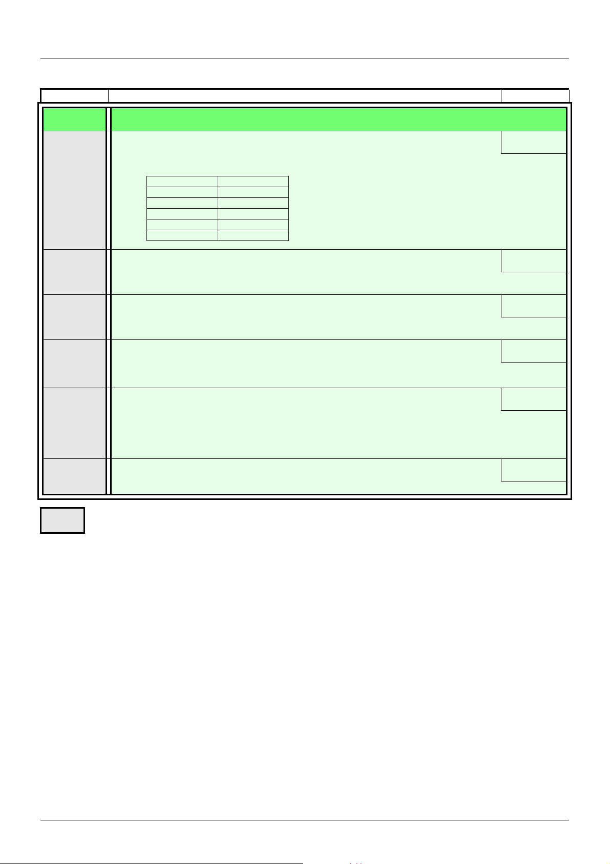
Monitoring mode MOn
Code Name/Description Unit
900-
909
910
911
912
913
r0t0
rOt1
r1t0
r1t1
Maintenance menu (continued)
M Run elapsed time display
Total time the motor has been powered up. Range: 0 to 65535 hours. Value displayed is as described in the
table below. Parameter resettable by services.
Hours Display
1 0.01
10 0.10
100 1.00
1000 10.0
10000 100
M Power On time display
Total time the drive has been powered on. Range: 0 to 65535 hours. Value displayed is as described in the
table above. Parameter resettable by services.
M Fan time display
Range: 0 to 65535 hours. Value displayed is as described in the table above. Parameter resettable by
customer.
M Process elapsed time
Range: 0 to 65535 hours. Value displayed is as described in the table above. Parameter resettable by
customer.
M Modbus communication status
v Modbus no reception, no transmission = communication idle
v Modbus no reception, transmission
v Modbus reception, no transmission
v Modbus reception and transmission
0.01
0.01
0.01
0.01
-
914
M Last fault 1
This parameter describes the Last fault.
Parameter that can be modified during operation or when stopped.
-
EAV94277 11/2020 49
Page 50
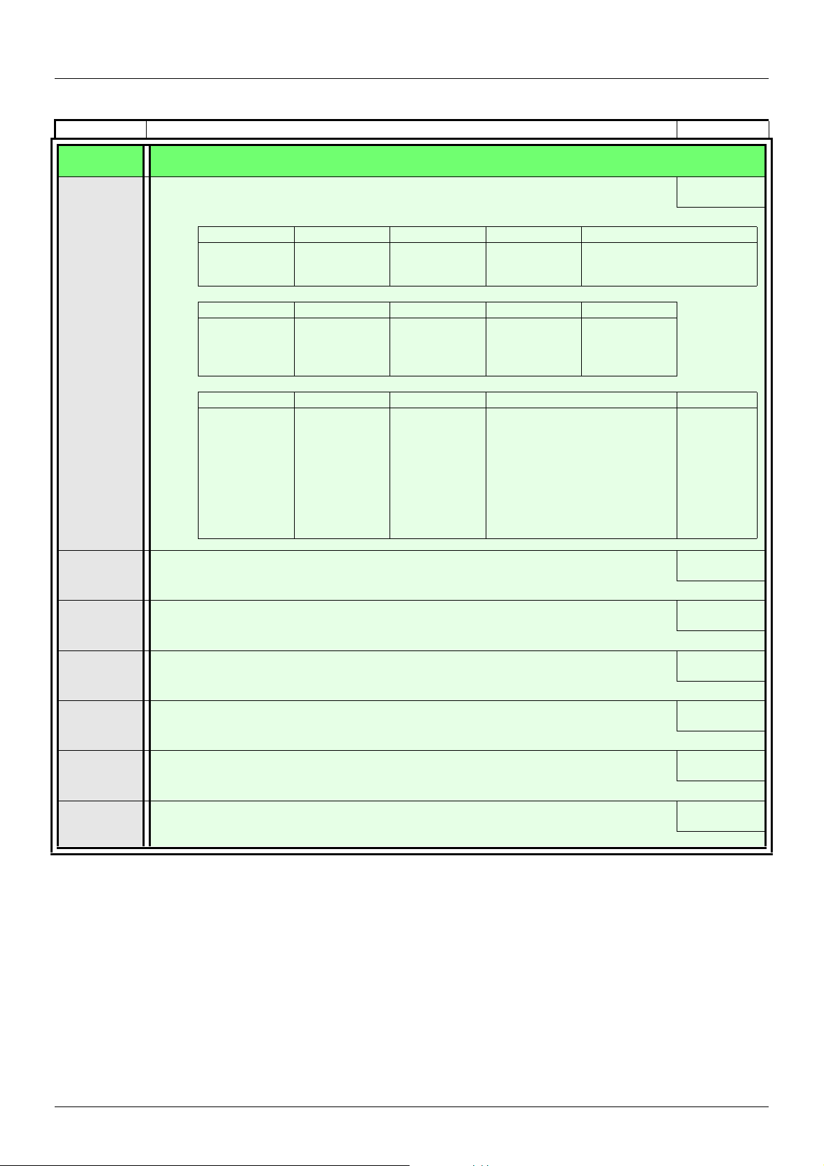
Monitoring mode MOn
Code Name/Description Unit
900-
915
Maintenance menu (continued)
M State of drive at fault 1
This parameter describes the drive state at the moment of the first detected fault.
bit 0 bit 1 bit 2 bit 3 bit 4
ETA.1: Switched
on
bit 5 bit 6 bit 7 bit 8 bit 9
ETI.4: Run order
present
bit 10 bit 11 bit 12 bit 13 - 14 bit 15
ETI.10 : Product
in deceleration
ETA.5:
Fast stop
ETI.5:
DC injection
running
ETI.11 : Current
limitation or
torque
limitation is
running
ETA.6:
Switch on
disabled
ETI.7:
Motor thermal
threshold
reached
Fast stop in
progress
Forced local
enabled
ETI.8: Reserved ETI.9:
ETI.14= 0 + ETI.13=0 :
Drive controlled by terminal or local
display terminal
ETI.14= 0 + ETI.13=1 :
Drive controlled by remote display
terminal
ETI.14= 1 + ETI.13=0 :
Drive controlled by Modbus
ETI.14= 1 + ETI.13=0 : Reserved
Motor rotation in forward
Product in
acceleration
ETA.15 :
direction (or stopped)
-
ETI.15 :
Reverse
direction
applied to
the ramp
916
917
918
919
920
921
M Last fault 2
This parameter describes the second detected fault.
M State of drive at fault 2
This parameter describes the drive state at the moment of the second detected fault. See 915.
M Last fault 3
This parameter describes the third detected fault.
M State of drive at fault 3
This parameter describes the drive state at the moment of the third detected fault. See 915.
M Last fault 4
This parameter describes the fourth detected fault.
M State of drive at fault 4
This parameter describes the drive state at the moment of the fourth detected fault. See 915.
-
-
-
-
-
-
50 EAV94277 11/2020
Page 51

Monitoring mode MOn
Code Name/Description Adjustment range Factory setting
999
OFF
On
M HMI Password
Possible state value:
v Password disabled
v Password activated
Range: 2 - 9999
If you have lost your password, please contact Schneider Electric.
This parameter is used to restrict access to the drive.
To lock the drive, go to the HMI Password999 parameter and enter a password within the above range.
Once activated, the password state changes to On:
Password protection only enables access to Reference ( rEF) (see page 44
page 52
To unlock the drive, go to the 999 parameter, enter the valid password, then press ENT.
Password protection removal is then possible and carried out by entering OFF using the jog dial and then
pressing ENT.
) mode. Return to factory settings or access to FULL section are disabled.
2 - 9999 OFF
) mode and Monitor (800-) (see
EAV94277 11/2020 51
Page 52

Configuration mode, ConF
The Configuration mode comprises 2 parts :
1. Store/recall parameter set: these 2 functions are used to store and recall customer settings.
2. FULL: This menu permits to access to all other parameters. It includes 6 sub-menus:
- Macro-configuration 100- (page 54)
- Input Output menu 200- (page55)
- Motor Control menu 300- (page 65)
- Control menu 400- (page 72)
- Function menu 500- (page 74)
- Fault detection management menu 600- (page 102)
- Communication menu 700- (page 109)
Organization tree
ConF
ENT
101
1.
102
2.
(1) Determined by active reference channel.
Possible values: 402 or 403
ENT
ESC
ENT
ESC
ENT
ESC
nO
nO
(2) 2 s or ESC
ENT
ENT
ESC
100
200++-
300-
400-
500-
600-
700-
Displayed parameter values are given as examples only.
52 EAV94277 11/2020
Page 53
Configuration Mode
2 s
2 s
2 s
Code Name/Description Adjustment range Factory setting
101
102
00
01
00
02
64
M Store customer parameter set
This function creates a backup of the present configuration:
00
v Function inactive
v Saves the current configuration in the drive memory.101 automatically switches to 00 as soon as the
save has been performed.
When a drive leaves the factory the current configuration and the backup configuration are both initialized
with the factory configuration.
M Factory / recall customer parameter set
This function permits restoration of a configuration.
00
v Function inactive
As soon as one of the following action has been performed,102 automatically changes to 00.
v The current configuration becomes identical to the backup configuration previously saved by 101.
As soon as this action has been performed,102 automatically changes to 0002 is only visible if the
backup has been carried out. If this value appears, 64 is not visible.
v The current configuration becomes identical to the factory setting. If this value appears, 64 is not visible.
WARNING
UNANTICIPATED EQUIPMENT OPERATION
Verify that restoring the factory settings is compatible with the type of wiring used.
Failure to follow these instructions can result in death, serious injury, or equipment damage.
To change the assignment of this parameter, press ENT key for 2 s.
How to control the drive locally
In factory setting, RUN, STOP and jog dial are inactive. To control the drive locally, adjust the following parameters:
Set Reference channel 1 401 (page 72
) to 183 (use integrated display with jog dial).
LI assignment information
It is possible with ATV310 to use multi assignment function (ie: 501.4 and 503 on the same LI).
It is also possible on some functions to assign LIH (high) or LIL (low), which means that the assigned function will be activated to high (LIH) or
low level (LIL) of LI.
Parameter that can be modified during operation or when stopped.
EAV94277 11/2020 53
Page 54
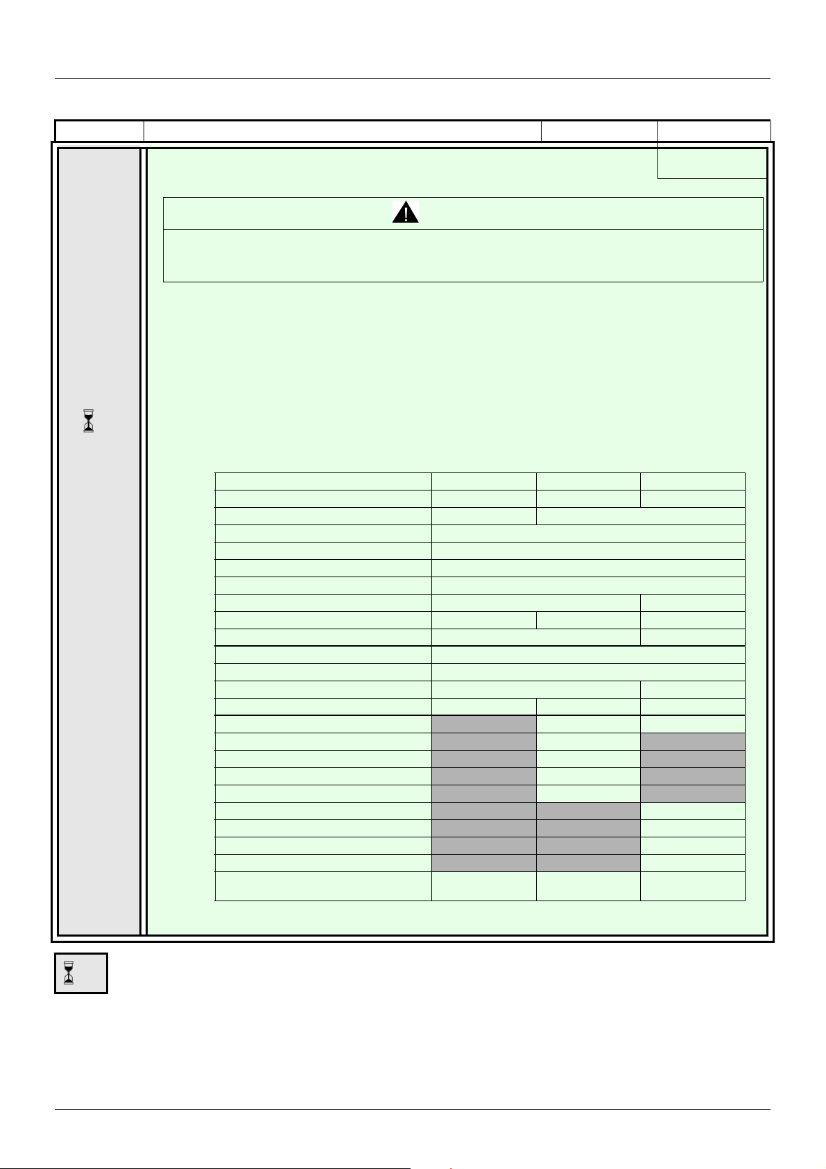
Configuration Mode - Complete menu (FULL)
2 s
Input / output or parameter Start/stop PID regulation Speed
AI1 Ref. channel 1 PID feedback NONE
AIV1 NONE Ref. channel 1
AO1 NONE
LO1 NONE
R1 No drive detected fault
L1h (2-wire) For ward
L2h (2-wire) NONE Reverse
L3h (2-wire) NONE Auto/Manual 2 preset speeds
L4h (2-wire) NONE 4 preset speeds
L1h (3-wire) Sto p
L2h (3-wire) For ward
L3h (3-wire) NON E Reve rse
L4h (3-wire) NONE Auto/Manual 2 preset speeds
401 (Reference source 1)
Integrated Jog dial Integrated Jog dial
309 (Motor control type)
Pump: 309=06
404 (Reverse inhibition) Yes
204.0 (AI1 type) 10A
LFLl (4-20 mA signal loss) YES
507.3 (Preset speed 2) 10.0Hz
507.4 (Preset speed 3)
25.0Hz
507.5 (Preset speed 4)
50.0Hz
319 (Motor parameter choice)
Motor power factor
504.0 (Automatic DC injection)
Limited DC
injection
Limited DC
injection
Limited DC
injection
2 s
Code Name/Description Adjustment range Factory setting
100
00
04
09
M Macro-configuration
StS
WARNING
UNANTICIPATED EQUIPMENT OPERATION
Verify that the selected macro configuration is compatible with the type of wiring used.
Failure to follow these instructions can result in death, serious injury or equipment damage.
Macro configuration provides a shortcut to configure a set of parameters suited to a specific field of
application.
3 macro configurations are available:
v Start/stop. Only forward is assigned.
v PID regulation. Activate PID function, dedicate AI1 for feedback and AIV1 for reference.
v Speed. Allocate LI to a preset speed which provides a means of configuring speed functions for a specific
field of application.
This parameter must be set before performing an autotuning.
Selecting a macro configuration assigns the parameters in this macro configuration.
Each macro configuration can still be modified in other menus.
54 EAV94277 11/2020
To change the assignment of this parameter, press the ENT key for 2 s.
Page 55
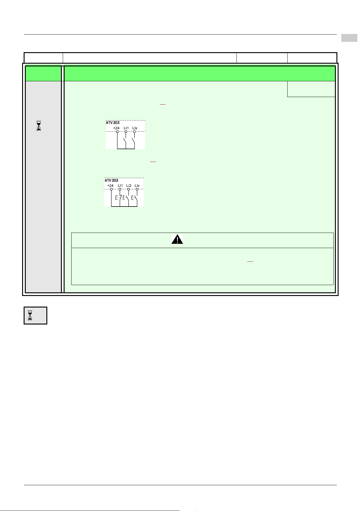
Configuration Mode - Complete menu (FULL)
200-
300-
400-
500-
600-
700-
2 s
2 s
Code Name/Description Adjustment range Factory setting
200-
201
00
01
I/O MENU
M Type of control
00
v 2 wire type control (see page 59)
The open or closed state of the input controls running and stopping.
Example of "source" wiring:
LI1: forward
LIx: reverse
v 3-wire control (see page 59)
"Forward" or "reverse" pulse send a run command. A "stop" pulse sends a stop command.
Example of "source" wiring:
LI1: stop
LI2: forward
LIx: reverse
This parameter must be set before performing an autotuning.
WARNING
UNANTICIPATED EQUIPMENT OPERATION
If this parameter is changed, the parameters 2-wire type control 202 (page 59) and the assignments of the digital
inputs are reset to the factory setting.
Verify that this change is compatible with the type of wiring used.
Failure to follow these instructions can result in death, serious injury or equipment damage.
To change the assignment of this parameter, press the ENT key for 2 s.
EAV94277 11/2020 55
Page 56

Configuration Mode - Complete menu (FULL)
200-
300-
400-
500-
600-
700-
Level detection diagram with no priority
Level detection diagram with forward priority
2 wire type control diagrams (see page 59)
56 EAV94277 11/2020
Page 57
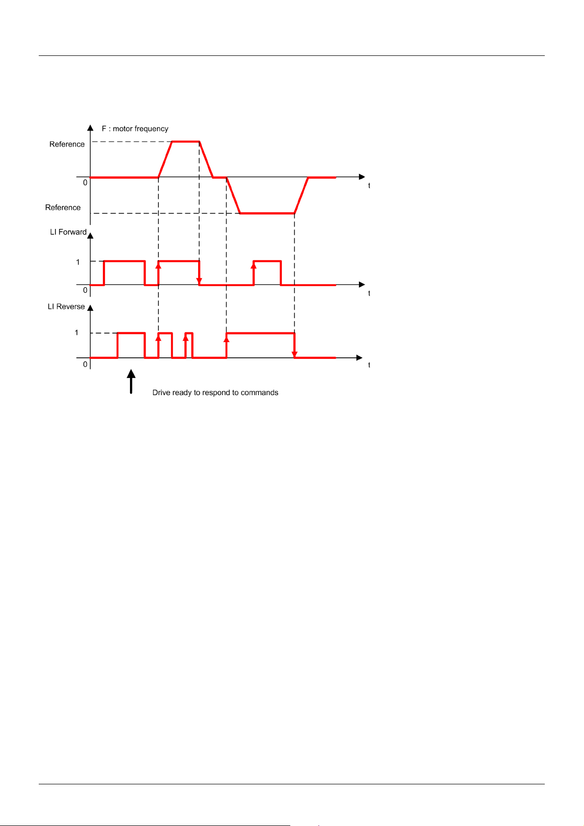
Configuration Mode - Complete menu (FULL)
Transition detection diagram
EAV94277 11/2020 57
Page 58
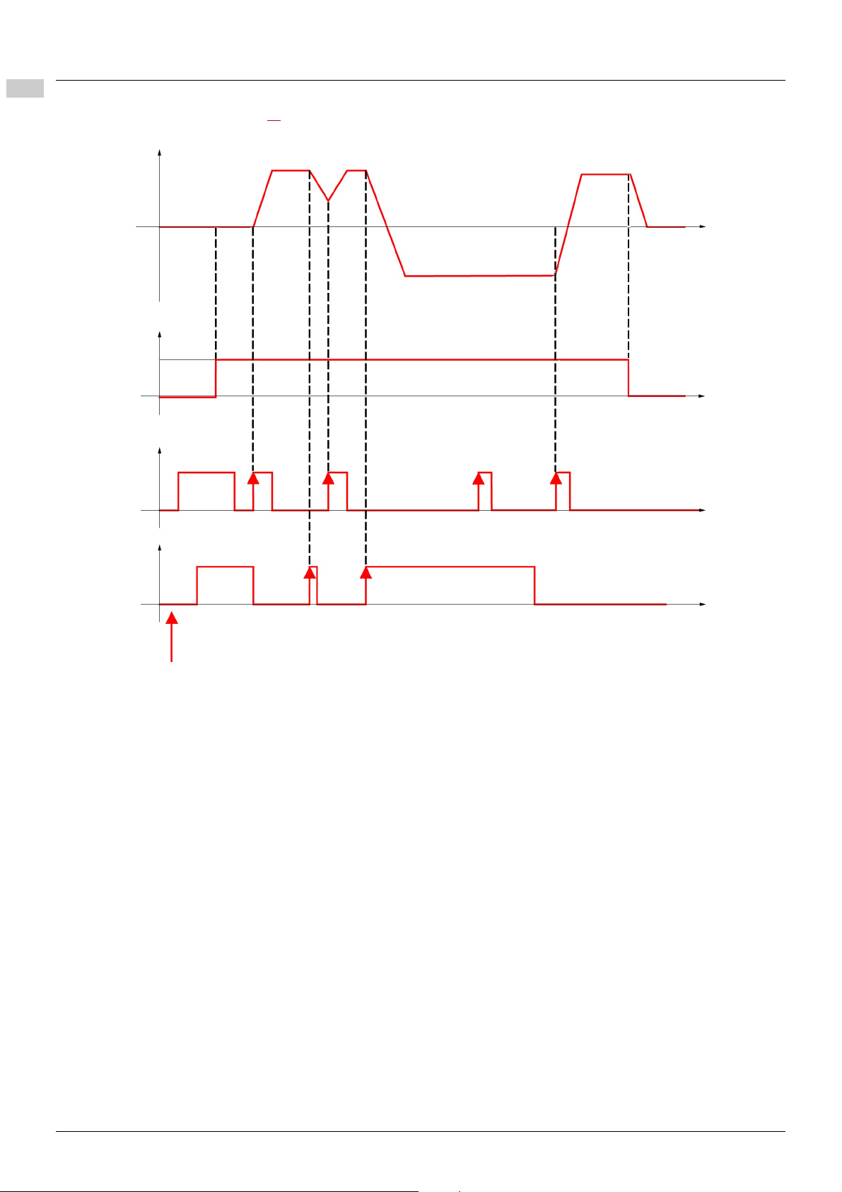
200-
300-
400-
500-
600-
700-
F: motor frequency
LI Run Enable
LI Forward
t
t
t
Reference
Drive ready to respond to commands
t
LI Reverse
Configuration Mode - Complete menu (FULL)
3-wire control diagrams (see page 59)
58 EAV94277 11/2020
Page 59
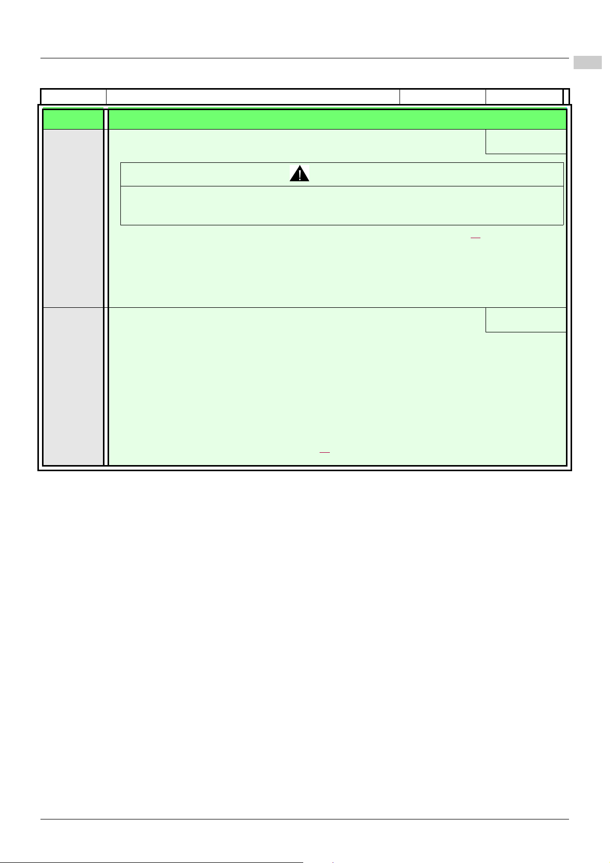
Configuration Mode - Complete menu (FULL)
200-
300-
400-
500-
600-
700-
Code Name/Description Adjustment range Factory setting
200- I/O MENU (continued)
202
203
00
01
02
00
01
02
M 2-wire type control
01
WARNING
UNANTICIPATED EQUIPMENT OPERATION
Verify that the parameter setting is compatible with the type of wiring used.
Failure to follow these instructions can result in death, serious injury or equipment damage.
2-wire type control parameter can only be accessed if Type of control 201 (page 55) is set to 2C.
v Level 0/1: Run or stop determined by level state 0 or 1.
v Transition: A change of state (transition or edge) is necessary to initiate operation, to help prevent
accidental restarts after a power supply interruption.
v Priority FW: Run or stop determined by state 0 or 1, but "forward" input takes priority over the "reverse"
input.
M Logic inputs type
v Positive: the inputs are active (state 1) at a voltage equal to or hig her th an 11 V (for example +24 V terminal).
They are inactive (state 0) when the drive is disconnected or at a voltage lower than 5 V.
v Negative using internal supply: the inputs are active (state 1) at a voltage lower than 10 V (for example COM
terminal). They are inactive (state 0) at a voltage equal to or higher than 16 V or when the drive is
disconnected.
v Negative using external sup pl y: t he i npu ts a re a ct ive (st ate 1) a t a v ol tag e lo wer tha n 10 V ( for exa mpl e CO M
terminal). They are inactive (state 0) at a voltage equal to or higher than 16 V.
Note: The modification will be taken into account only at the next control power-on.
00
See Control connection diagrams on page 34
.
EAV94277 11/2020 59
Page 60

Configuration Mode - Complete menu (FULL)
200-
300-
400-
500-
600-
700-
Code Name/Description Adjustment range Factory setting
200- I/O MENU (continued)
204-
204.0
204.1
204.2
200-
205
5U
10U
0A
LIU
00
01
02
04
05
06
07
08
21
22
123
AI1 CONFIGURATION MENU
M AI1 type
This function establishes an interface between the analog input signal and drive internal value.
v Voltage: 0-5 Vdc
v Voltage: 0-10 Vdc
v Current: x-y mA. Range determined by the AI1 current scaling parameter of 0% 204.1 and AI1 current
scaling parameter of 100% 204.2 settings below. See page 60
v Logic input. AI1 must be wired the same way as a logic input LIx in source mode.
M AI1 current scaling parameter of 0%
Visible only if AI1 type 204.0 is set to 0A.
M AI1 current scaling parameter of 100%
Visible only if AI1 type 204.0 is set to 0A.
I/O MENU (continued)
M R1 assignment
v Not assigned
v No fault
v Drive run
v Frequency threshold reached
v Motor frequency when max. reference value reached 512.2
v I threshold reached
v Frequency reference reached
v Motor thermal threshold reached
v Underload alarm
v Overload alarm
v 4-20 mA signal loss visible only if 204.0 is set to 0A (see above).
Note: Relay R1 can be assigned to upstream protection to avoid overvoltage in the drive:
• Connect fault relay R1 to the contactor, see schematic page 23
• Use Relay R1 (R1 assignment 205 ) with protection.
• Use LO1 assignment 206.0 (page 61
) for remote indication of the drive status.
5U
.
0 - 20 mA 4 mA
0 - 20 mA 20 mA
01
.
60 EAV94277 11/2020
Page 61
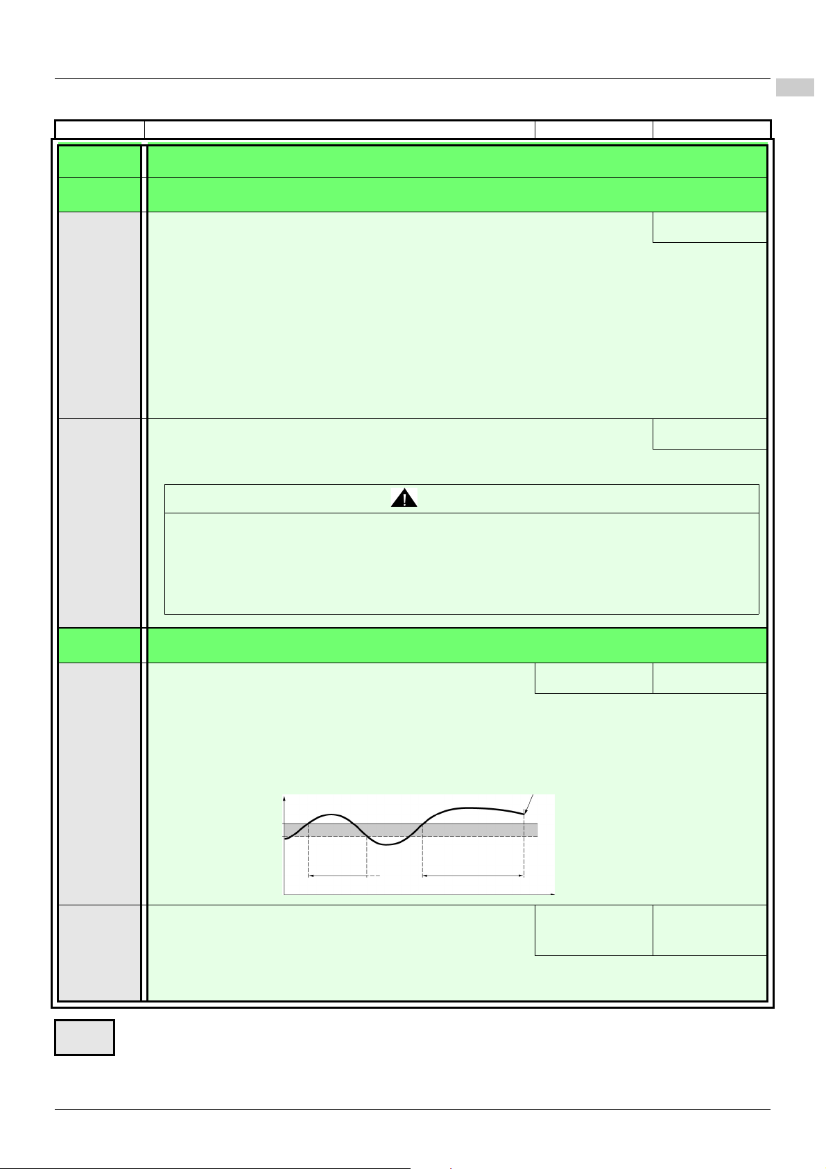
Configuration Mode - Complete menu (FULL)
200-
300-
400-
500-
600-
700-
208
Estimated motor current
208 -10%
Drive stop on detection of F012 fault.
207
< 207
(hysteresis)
t
Code Name/Description Adjustment range Factory setting
200-
206-
206.0
206.1
00
01
02
04
05
06
07
08
21
22
123
126
00
01
I/O MENU (continued)
LO1 CONFIGURATION MENU
M LO1 assignment
v Not assigned
v No fault
v Drive run
v Frequency threshold reached
v Motor frequency when max. reference value reached 512.2
v I threshold reached
v Frequency reference reached
v Motor thermal threshold reached
v Underload alarm
v Overload alarm
v 4-20 mA signal loss visible only if 204.0 is set to 0A (see above).
v Auxiliary pump
M LO1 status (output active level)
v Positive logic: active high
v Negative logic: active low
00
00
WARNING
LOSS OF CONTROL
Depending on the assignments and settings of the logic outputs, signal output functions may not be effective if the
wiring is incorrect or inoperative.
• Do not set this parameter to 01 unless you can ensure that the signal will be available under all circumstances.
• Verify correct settings for all parameters used to set signal output functions.
Failure to follow these instructions can result in death, serious injury or equipment damage.
200-
207
208
EAV94277 11/2020 61
I/O MENU (continued)
M Application Overload time delay
This function can be used to stop the motor in the event of an application overload. This is not a motor or drive
thermal overload. If the motor current exceeds the Application Overload threshold 208, an Application
Overload time delay 207 is activated. Once this time delay 207 has elapsed, if the current is still greater than
the overload thresho ld 208 -10%, the drive will stop running and display Process overload.
Overload detection is only active when the system is in steady state (Actual speed reference reached).
A value of 0 will disable application overload detection.
M Application Overload threshold
Visible only if Overload time delay 207 above is not 0.
This parameter is used to detect an "application overload". 208 can be adjusted between 70 and 150% of
the rated drive current. This is not the same as a motor or drive thermal overload.
Parameter that can be modified during operation or when stopped.
0 to 100 s 0 s
70% - 150% of 305
parameter value
70% - 150%
90% of 305
parameter value
Page 62

Configuration Mode - Complete menu (FULL)
200-
300-
400-
500-
600-
700-
211 +10%
Estimated motor current
211
When F029 fault is
detected
210< 210
(hysteresis)
t
Code Name/Description Adjustment range Factory setting
200-
209
210
211
I/O MENU (continued)
M Time delay before automatic start for the
overload fault
If 602.0=01, the drive will automatically restart after this time delay following the overload fault F012.
Minimum time permitted between an overload being detected and any automatic restart.
In order for an automatic restart to be possib le, the maximum restart time 602.1 (page 102
that of this parameter by at least one minute.
Visible only if the "Overload time delay 207" above is not set to 0.
M Application underload time delay
210 can be adjust between 0 to 100 s
If the motor current undershoots the underload threshold 211 for longer than the adjustable time delay
210, the drive will stop running and display F029 (Underload fault), see page 115
Underload detection is only active when the system is in steady state (Actual speed reference reached).
A value of 0 will disable application underload detection.
M Application Underload threshold
Visible only if Underload time delay 210 is not set to 0. This parameter is used to detect an application
underload condition on the motor. Application Underload threshold 211 can be adjusted between 20 and
100% of the rated drive current.
0-6 min. 0 min.
0 to 100 s 0 s
.
20% to 100% of 305
parameter
60%
) must exceed
212
213
214
215
(1) In = rated drive current
M Underload fault duration start
If 602.001, the drive will automatically restart after this ti me delay following the underload fault F029.
Minimum time permitted between an underload being detected and any automatic restart.
In order for an automatic restart to be possib le, the maximum restart time 602.1 (page 102
that of this parameter by at least one minute.
Visible only if the "Application underload time delay 210" above is not set to 0.
M Motor frequency threshold
Visible only if R1 assignment 205 (page 60) or LO1 assignment 206.0 (page 61) is set to 04.
M Motor current threshold
Visible only if R1 assignment 205 (page 60) or LO1 assignment 206.0 (page 61) is set to 06.
M Motor thermal state threshold
Visible only if R1 assignment 205 (page 60) is set to 08.
Trip threshold for motor thermal alarm (logic output or relay)
Parameter that can be modified during operation or when stopped.
0-6 min. 0 min.
) must exceed
0 to 400 Hz 50 or 60 Hz,
Determined by
drive rating
0 to 1.5 In (1) In
0 to 118% of 808
parameter
100%
62 EAV94277 11/2020
Page 63

Configuration Mode - Complete menu (FULL)
200-
300-
400-
500-
600-
700-
Code Name/Description Adjustment range Factory setting
200-
216-
216.0
216.1
00
129
130
131
135
136
137
139
140
141
10U
0A
4A
I/O MENU (continued)
AO1 configuration menu
M AO1 assignment
This parameter is used to set the value of an analog output.
v Not assigned
v Estimated motor current, between 0 and 2xDrive nominal current
v Estimated motor frequency, between 0 and Maximum Frequency
v Ramp output, between 0 and Maximum Frequency
v PID reference value
v PID feedback
v PID error
(1)
, between -5% and +5%
v Output power, between 0 and 2xMotor nominal power
v Motor thermal state, between 0% and 200%
v Drive thermal state, between 0% and 200%
(1) Visible only if PID feedback assignment 59.00 (page 85
M AO1 type
This parameter provides type selection for the drive analog output signal.
v Voltage: 0-10 Vdc
v Current: 0-20 mA
v Current: 4-20 mA
(1)
(1)
, between 0% and 100%
, between 0% and 100%
00
) is not set to 00.
0A
EAV94277 11/2020 63
Page 64

Configuration Mode - Complete menu (FULL)
200-
300-
400-
500-
600-
700-
Frequency
reference
512.0
-100%
+100%
512.2
512.0
512.2
0%
Frequency
reference
512.0
-100%
+100%
512.2
512.0
512.2
0
Frequency
reference
512.0
-100%
+100%
512.2
512.0
512.2
Frequency
reference
512.0
-100%
+100%
512.2
512.0
512.2
0%
Code Name/Description Adjustment range Factory setting
200-
217
BSD
BNS
I/O MENU (continued)
M Reference Template
This parameter defines how the speed reference is taken into account for analog inputs only.
In the case of the PID controller, BNS and BNS0 are not applied. The limits are set by the Low Speed
512.0 and High Speed 512.2 parameters.
v Standard
v Deadband
bsd
At zero reference the frequency = 512.0
At reference = 0 to 512.0 the frequency = 0
v Pedestral
At zero reference to 512.0, the frequency = 512.0
BLS
v Deadband at 0%
This operation is the same as BSD Standard,
BNS0
64 EAV94277 11/2020
except that in the following cases at zero
reference, the frequency = 0: the signal is less
than the minimum value, which is greater than 0
(example: 2 mA on a 4–20 mA input). The signal
is greater than minimum value, which is greater
than the maximum value (example: 21 mA on a
20–4 mA input)
Page 65

200-
300-
400-
500-
600-
700-
Configuration Mode - Complete menu (FULL)
WARNING
LOSS OF CONTROL
• Fully read and understand the manual of the connected motor.
• Verify that all motor parameters are correctly set by referring to the nameplate and the manual of the connected motor.
• If you modify the value of one or more motor parameters after having performed auto-tuning, the value of Auto-tuning is reset to 00 and
you must re-perform auto-tuning.
Failure to follow these instructions can result in death, serious injury or equipment damage.
Code Name/Description Adjustment range Factory setting
300-
301
302
303
Motor control menu
M Standard motor frequency
This parameter must be set before performing an autotuning.
M Rated Motor Power
This parameter must be set before performing an autotuning.
M Rated motor cos phi
This parameter is v isible only if Motor parameter choice 319 (page 69) is set to [00]. If Rated motor cos phi
303 is available, Rated Motor Power 302 disappears.
Power factor (pf) is given on the motor rating plate.
Drive power -5 to
drive power +2
according to dual
rating
0.5 to 1
50 Hz
Determined by drive rating
and dual rating
Determined by drive rating
and dual rating
304
305
306
307
This parameter must be set before performing an autotuning.
Note: Do not confuse this with motor "Service Factor". Setting 303 to 1 or very near to 1 may result in
unsatisfactory motor operation. If the motor power factor is not indicated on the nameplate, leave this
parameter at the factory default (approximately 0.80).
M Rated motor voltage
Nominal motor voltage is given on the nameplate. If the line voltage is less than the nominal motor voltage,
Rated motor voltage 304 should be set to the value of the line voltage applied to the drive terminals.
This parameter must be set before performing an autotuning.
M Rated motor current
Nominal motor current is given on the nameplate. Motor thermal current 604.0 (page 105) varies according
to the nominal motor current 305.
This parameter must be set before performing an autotuning.
M Rated motor frequency
Nominal motor frequency is given on the nameplat e.
The factory setting is 50 Hz, or preset to 60 Hz [if Standard motor frequency 301 (page 65
This parameter must be set before performing an autotuning.
M Rated motor speed
Nominal motor speed is given on the nameplate.
360 to 460V 380V
0.25 In to 1.5 In (1) Determined by drive rating
and dual rating
10 to 400 Hz 50 Hz
) is set to 60 Hz].
0 to 24000 rpM
Determined by drive rating
and dual rating
This parameter must be set before performing an autotuning.
(1) In = rated drive current
EAV94277 11/2020 65
Page 66
Configuration Mode - Complete menu (FULL)
200-
300-
400-
500-
600-
700-
Code Name/Description Adjustment range Factory setting
300-
308
309
Motor control menu (continued)
M Maximum frequency
Maximum frequency 308 gives the upper value possible for High speed 512.2 (page 101). The factory
setting is 60 Hz, or preset to 72 Hz [if Standard motor frequency 301 (page 65
This parameter must be set before performing an autotuning.
M Motor control type
Permits selection of motor control types suitable for application and performance requirements.
00
03
06
v Performance: Sensorless vector control with internal speed loop based on a voltage feedback calculation. For
applications requiring high performance during starting or operation.
v Standard: 2 point V/F control without internal speed loop.
For simple applications that do not require high performance. Simple motor control law maintaining a
constant Voltage Frequency ratio, permits adjustment of curve start point.
This law is generally used for motors connected in parallel. Some applications using motors in parallel or with
high performance requirements may require use of the "high performance" (00) control type.
v Pump: U
torque.
2
/F; for dedicated use with variable torque fan and pump applications not requiring high starting
10 to 400 Hz 60 Hz
) is set to 60 Hz].
03
66 EAV94277 11/2020
Page 67
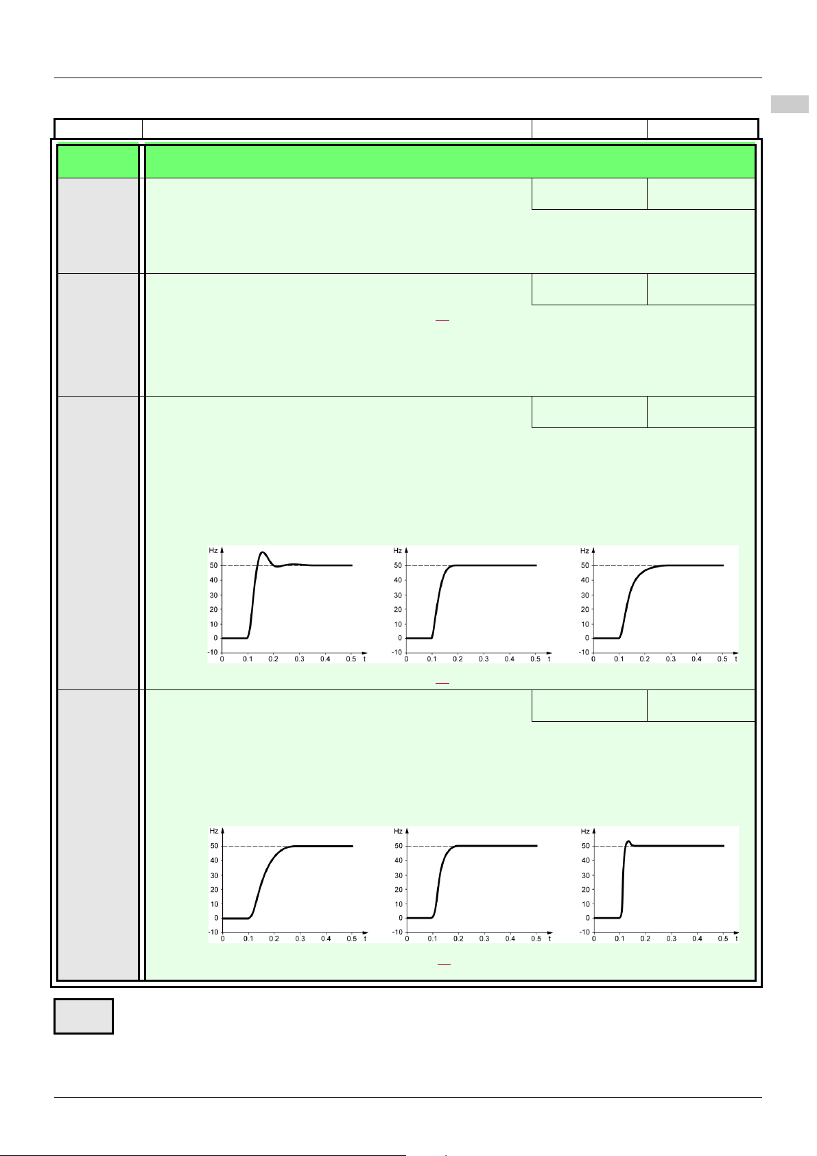
Configuration Mode - Complete menu (FULL)
200-
300-
400-
500-
600-
700-
Code Name/Description Adjustment range Factory setting
300-
310
311
312
Motor control menu (continued)
M IR compensation
Used to optimize torque at very low speed, or to adapt to special cases (for example, for motors connected
in parallel, decrease IR compensation 310). If there is insufficient torque at low speed, increase IR
compensation 310. Too high a value can cause the motor not to start (locking) or to change to current
limiting mode.
M Slip compensation
Visible only ifMotor control type 309 (page 66) is not set to 06.
Used to adjust the slip compensation around the value set by the nominal motor slip, or to adjust to special
circumstances (for example, for motors connected in parallel, decrease Slip compensation 311).
If the set slip compensation is lower than the actual slip compensation, the motor will not run at nominal
speed in a steady state but at a speed lower than the reference.
If the set slip compensation is greater than the actual slip compensation, the motor speed becomes unstable.
M Frequency loop stability
The 312 parameter can be used to reduce overshoots and oscillations at the end of acceleration. After a
period of acceleration or deceleration, 312 adjusts the return value of the steady state to the dynamic
value of the equipment;
Too high a value can cause an extended response time.
Too low a value can cause overspeed, or even instability.
Low 312 parameter value Correct 312 parameter value High 312 parameter value
In this case, increase 312 In this case, reduce 312
25 to 200% 100%
0 to 150% 100%
0 to 100% 20%
313
Visible only ifMotor control type 309 (page 66
) is set to 00.
M Frequency loop gain
The 313 parameter adjusts the slope of the speed increase according to the inertia of the machine being
driven.
Too high a value can cause overspeed, or even instability.
Too low a value can cause an extended response time.
Low 313 parameter value Correct 313 parameter value High 313 parameter value
In this case, increase 313 In this case, reduce 313
Visible only if Motor control type 309 (page 66
Parameter that can be modified during operation or when stopped.
0 to 100% 20%
) is set to 00.
EAV94277 11/2020 67
Page 68

Configuration Mode - Complete menu (FULL)
200-
300-
400-
500-
600-
700-
314
Parameter
value
314
Parameter
value
100%
Code Name/Description Adjustment range Factory setting
300-
314
315
317
Motor control menu (continued)
M Flux Profile
This function defines the magnetizing current at zero frequency as a % of the rated magnetizing current.
Adjustment curve for PUMP law
Visible only if Motor control type 309 (page 66
M Switching frequency
Switching frequency range setting.
In the event of overheating, the drive automatically decreases the Switching frequency range. Returns to its
original value once the temperature has returned to normal.
M Motor noise reduction
0 to 100% 20%
Frequency
) is set to 06.
2 to 12 kHz 4 kHz
00
Noise refers to audible noise. Means of adjusting motor noise must be provided to satisfy environmental
requirements.
Random frequency modulation avoids possible noise resonance that can occur at fixed frequency.
00
01
Parameter that can be modified during operation or when stopped.
v No
v Yes
68 EAV94277 11/2020
Page 69
Configuration Mode - Complete menu (FULL)
200-
300-
400-
500-
600-
700-
Code Name/Description Adjustment range Factory setting
300-
318
Motor control menu (continued)
M Auto-tuning
UNEXPECTED MOVEMENT
Autotuning moves the motor in order to tune the control loops.
• Only start the system if there are no persons or obstructions in the zone of operation.
Failure to follow these instructions can result in death, serious injury or equipment damage.
During autotuning, noise development and oscillations of the system are normal.
LOSS OF CONTROL
If you modify the value of one or more motor parameters after having performed auto-tuning, the value of Auto-
tuning is reset to 00 and you must re-perform auto-tuning.
Failure to follow these instructions can result in death, serious injury or equipment damage.
00
01
02
v 00: Use factory parameters for standard motors
v 01: Launches auto-tuning
v 02: Auto-tuning has already been performed
Attention:
• Auto-tuning must be performed with the motor connected and cold.
• The parameters Rated Motor Power 302 (page 65
consistent.
• Auto-tuning is performed only if no stop command has been activated. If a freewheel stop or fast stop
function has been assigned to a logic input, this input must be set to 1 (active at 0).
• Auto-tuning takes priority over any run or prefluxing commands, which will take effect after the autotuning sequence.
• Auto-tuning may last for 1 to 10 seconds. Do not interrupt. Wait for the display to change to 02 or 00.
• Re-perform auto-tuning after motor cables are replaced to ensure effectiveness of motor control.
00
WARNING
WARNING
) and Rated motor current 305 (page 65) must be
319
00
01
Note: During auto-tuning, the motor operates at rated current.
M Motor parameter choice
This parameter allows to choose which motor parameter will be configured (power or power factor).
This parameter must be set before performing an autotuning.
v Rated Motor Power (page 65)
v Rated motor cos phi (page 65)
00
EAV94277 11/2020 69
Page 70
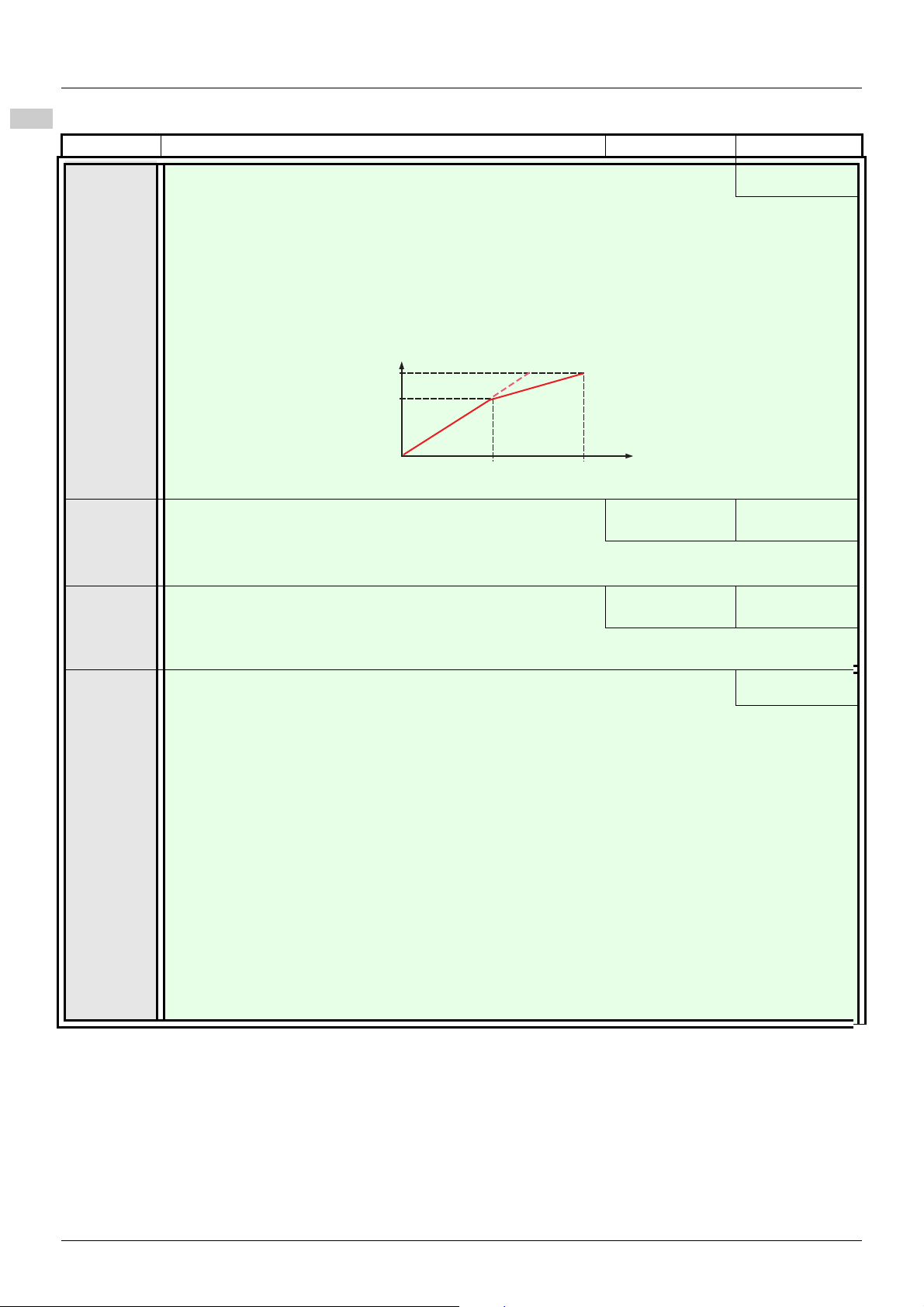
Configuration Mode - Complete menu (FULL)
200-
300-
400-
500-
600-
700-
Maximum Voltage 321
Motor Rated Voltage 304
Motor Rated Frequency 301
Maximum Frequency 322
Frequency
Motor voltage
Code Name/Description Adjustment range Factory setting
320
321
322
00
01
M Vector control 2 points
v [00] No
v [01] Yes
For use in the following application contexts: when the rated speed and rated frequency of the motor must
be exceeded for optimization of operation performance at constant power, or when the maximum voltage
of the motor must be limited to a certain value below the main voltage.
The U/F diagram must therefore be modified according to the motor's wor k ability at maximum voltage and
Top frequency.
M Max voltage of constant power
Visible if 320 = YES
M Max frequency of constant power
Visible if 320 = YES
314 parameter
value ~ 460V
306 parameter
value ~ 400Hz
00
380V
50Hz
323
00
01
M Dual Rating
This parameter is used to select the default value of rated drive current and motor nameplate.
This parameter cannot be modified on drive with power equal to or lower than 2.2 kW.
A modification of its setting resets several parameters of the drive:
- motor nameplate parameters (302, 303, 304, 305, 306, 307)
- status of tune results
- current parameters: In (drive rating current), motor thermal current (604.0), current limitation
(511.1 and 511.2), motor current threshold (214) and current injections (502.5, 502.7,
504.1).
This parameter must be set before performing an autotuning.
01
v Normal duty: Normal rating, dedicated mode for applications requiring slight overload (up to 1.1In for 60 s).
v Heavy duty: High rating, dedicated mode for applications requiring significant overload
(up to 1.5In for 60s).
NOTE: Both modes use the same hardware, the overload in normal duty is lower than the one in normal
duty, consequently, the rated drive current (In) in normal duty mode is adapted to be slightly higher than
the one in heavy duty mode. The default motor nameplate and other current limitation are adapted
accordingly.
70 EAV94277 11/2020
Page 71

200-
300-
400-
500-
600-
700-
407
507
505
nO
nO
5Hz
408
nO
LI
408
nO
LI
nO
LI
409
401
Modbus
409
405
nO
404
512.2
501.0
501.1
501.4 501.5
512.0
406
59.00
Analog terminal
Command channel 1
Channel
configuration
Reference
channel 1
Reverse inhibition
High speed
Low speed
Forced local assignment
Stop key priority
Forced local reference
Not assigned
Analog input terminal
Remote display
Integrated display with Jog dial
Forced local assignment
Jog assignment
Anolog terminal
Remote display
Integrated display
with Jog dial
Combined mode
Separate mode
Terminals
Local
Remote display
Modbus
Forced local
reference
Not assigned
Analog input terminal
Remote display
Integrated display
with Jog dial
Yes
No
2 preset speeds
Preset speeds
Preset speed 8
Preset speed 2
505 or 59.00
Configuration Mode - Complete menu (FULL)
Control menu
Control channel diagram
EAV94277 11/2020 71
Page 72

Configuration Mode - Complete menu (FULL)
200-
300-
400-
500-
600-
700-
2 s
2 s
Code Name/Description Adjustment range Factory setting
400-
l
401
402
403
404
405
01
163
164
183
00
01
Control menu
M Reference channel 1
v Anolog terminal
v Remote display
v Modbus
v Integrated display with Jog dial
M External reference value
M Analog input virtual
M Reverse inhibition
Inhibition of movement in the reverse direction. Does not apply to direction requests sent by logic inputs.
- Reverse direction requests sent by logic inputs are taken into account.
- Reverse direction requests sent by the display are not taken into account.
- Reverse direction requests sent by the communication line are not taken into account.
- Any reverse Actual speed reference originating from the PID, summing input etc., is interpreted as a zero
reference (0 Hz).
v No
v Yes
M Stop key priority
This parameter can enable or disable th e stop button located on the drive and remote display.
Disabling the stop button is effective if the active command channel is not the drive display terminal or the
remote display.
-400 Hz to 400 Hz
0% to 100%
01
-
00
01
LOSS OF CONTROL
The function Stop key priority 405 parameter disables the Stop keys of the drive and of the Remote Display Terminal
if the setting of the parameter is 00.
Only set this parameter to 00 if you have implemented appropriate alternative stop functions.
Failure to follow these instructions can result in death, serious injury or equipment damage.
00
01
406
01
02
To change the assignment of this parameter, press the ENT key for 2 s.
v No: Stop inactive
v Yes: Stop active
It is advised in case this fu nction is set to 01 to use the front door cover or the optional display cover on the
"run" and "stop" keys.
M Channel configuration
Channel configuration 406 allows the selection of:
- Combined mode (command and reference come from the same channel)
- Separate mode (command and reference come from different channels)
v Combined mode
v Separate mode
WARNING
01
72 EAV94277 11/2020
Parameter that can be modified during operation or when stopped.
Page 73

Configuration Mode - Complete menu (FULL)
200-
300-
400-
500-
600-
700-
Code Name/Description Adjustment range Factory setting
400-
407
408
409
01
02
03
10
00
L1H
L4H
LUH
00
01
163
183
Control menu (continued)
M Command channel 1
This parameter permits selection of the command channel.
v Terminals
v Local
v Remote display
v Modbus
Visible only if Channel configuration 406 (page 72
M Forced local assignment
v Function inactive
v L1h - L4H, LUH: Forced local mode is active when the input is at state 1.
-
M Forced local reference
Visible only if Forced local assignment 408 is not set to 00
v Not assigned
v Analog input terminal
v Remote display
v Integrated display with Jog dial
01
) is set to Seperate.
00
00
EAV94277 11/2020 73
Page 74

Configuration Mode - Complete menu (FULL)
200-
300-
400-
500-
600-
700-
Code Name/Description Adjustment range Factory setting
500-
501-
501.0
501.1
501.2
Function menu
Ramp menu
M Acceleration
M Deceleration
M Ramp shape assignment
00
01
02
S Shape
0.0 s to 999.9 s
Acceleration time between 0 Hz and the Rated motor frequency 306 (page 65).
Make sure this value is compatible with the inertia being driven.
0.0 s to 999.9 s
Time to decelerate from the Rated motor frequency 306 (page 65) to 0 Hz.
Make sure this value is compatible with the inertia being driven.
v Linear
v S Shape
v U Shape
The rounding coefficient is fixed, wherein
t1 = 0.6 x set ramp time (linear)
t2 = 0.4 x set ramp time (round)
t3 = 1.4 x ramp time
3.0 s
3.0 s
00
501.3
U Shape
M Ramp switching commutation
00
LIH
L2H
L3H
L4H
LUH
L1L
L2L
L3L
L4L
LUL
Parameter that can be modified during operation or when stopped.
v Not assigned
v L1H: LI1 active high
v L2H: LI2 active high
v L3H: LI3 active high
v L4H: LI4 active high
v LUH: LIU active high
v L1L: LI1 active low
v L2L: LI2 active low
v L3H: LI3 active low
v L4H: LI4 active low
v LUL: LIU active low
See LI assignment information on page 53
The rounding coefficient is fixed, wherein
t1 = 0.5 x set ramp time (linear)
t2 = set ramp time (round)
t3 = 1.5 x ramp time
00
.
74 EAV94277 11/2020
Page 75

Configuration Mode - Complete menu (FULL)
200-
300-
400-
500-
600-
700-
Code Name/Description Adjustment range Factory setting
500-
501-
501.4
501.5
501.6
Function menu (continued)
Ramp menu (continued)
M Acceleration 2
Visible only if Ramp switching commutation 501.3 (page 74) is not set to 00.
Second acceleration ramp time, adjustable from 0.0 to 999.9 s
This ramp becomes the active ramp only when PID is used to perform start and wake-up phases.
See PID: wake up level (page 88
M Deceleration 2
Visible only if Ramp switching commutation 501.3 (page 74) is not set to 00.
Second deceleration ramp time, adjustable from 0.0 to 999.9 s
M Decel Ramp Adaptation assignment
00
01
02
v Function inactive. The drive will decelerate based on normal deceleration time settings. This setting is
compatible with optional dynamic braking (if used).
v This function automatically increases deceleration time when stopping or reducing the speed of high inertia
loads to help prevent DC bus overvoltage or overbraking.
v Motor Braking: This mode allows the drive to attempt the most rapid stop possible without the use of a
dynamic brake resistor. It uses motor losses to dissipate energy generated by braking.
This function may be incompatible with positioning. This function should not be used when an optional
braking resistor and module are being used.
Attention: When using a braking resistor set 501.6 to 00.
0.0 to 999.9 s 5.0 s
).
0.0 to 999.9 s 5.0 s
01
Parameter that can be modified during operation or when stopped.
EAV94277 11/2020 75
Page 76

Configuration Mode - Complete menu (FULL)
200-
300-
400-
500-
600-
700-
Code Name/Description Adjustment range Factory setting
500-
502-
502.0
502.1
502.2
00
03
08
13
00
L1L
L2L
L3L
L4L
LUL
00
L1L
L2L
L3L
L4L
LUL
Function menu (continued)
Stop configuration menu
M Type of stop
Stop mode on disappearance of the run command or appearance of a stop command.
v Ramp stop
v DC injection stop
v Fast stop
v Freewheel stop
M Freewheel stop assignment
This stop type is activated when the input or corresponding register bit changes to 0. If the input returns to
state 1 and the run command is still active, the motor will only restart if Type of control 201 (page 55
and 2-wire type control 202 (page 59
v Not assigned
v L1L: LI1 active Low to stop
v L2L: LI2 active Low to stop
v L3L: LI3 active Low to stop
v L4L: LI4 active Low to stop
v LUL: LIU active Low to stop
M Fast stop assignment
v Not assigned
v L1L: LI1 active Low to stop
v L2L: LI2 active Low to stop
v L3L: LI3 active Low to stop
v L4L: LI4 active Low to stop
v LUL: LIU active Low to stop
00
00
) = 2C
) = 00 or 02. If not, a new run command must be sent.
00
502.3
M Ramp divider
Visible only if Fast stop assignment 502.2 (page 76) is not set to 00 or 502.2 is set to 08 Fast stop
(page 76
When stop requests are sent the active ramp time [Deceleration 501.1 (page 74
501.5 (page 75
Parameter that can be modified during operation or when stopped.
).
)] is divided by this coefficient.
1 to 10 4
) or Deceleration 2
76 EAV94277 11/2020
Page 77

Configuration Mode - Complete menu (FULL)
Code Name/Description Adjustment range Factory setting
500-
502-
502.4
502.5
00
L1H
L2H
L3H
L4H
LUH
Function menu (continued)
Stop configuration menu
M DC injection assignment
WARNING
UNINTENDED MOVEMENT
• Do not use DC injection to generate holding torque when the motor is at a standstill.
• Use a holding brake to keep the motor in the standstill position.
Failure to follow these instructions can result in death, serious injury, or equipment damage.
DC injection is activated when the input switches to 0. If the input returns to state 1 and the run command is still
active, the motor will only restart if Type of control 201 (page 55
59
) = 00 or 02. If not, a new run command must be sent.
This parameter is forced to 00 if Type of stop 502.0 is set to 08 (page 76
v Not assigned.
v L1h: L1 active high
v L2h: L2 active high
v L3h: L3 active high
v L4h: L4 active high
v LUh: LIU active high (AI1 used as logic input: AI1 type 204.0 sets to LIU)
M DC injection level
) = 2C and 2-wire type control 202 (page
)
0.1*In to 1.41*In (1) 0.64*In (in A)
00
OVERHEATING
Verify that the connected motor is properly rated for the DC injection current to be applied in terms of amount and
time.
Failure to follow these instructions can result in equipment damage.
502.6
M IDC injection time for DCLI
OVERHEATING
Verify that the connected motor is properly rated for the DC injection current to be applied in terms of amount and
time.
Failure to follow these instructions can result in equipment damage.
(1) In = rated drive current
Notice
Level of DC injection braking current activated via digital input or selected as stop mode.
This parameter can be accessed if DC injection assignment 502.4 is set to a value different from 00 or if
Type of stop 502.0 is set to DC injection stop 03.
NOTE: this setting is independent from the AUTO DC INJECTION MENU 504- function.
0.1 s to 30 s 0.5 s
Notice
Maximum current injection time DC injection level 502.5 . After this time, the injection current becomes DC
injection level 2 502.7 .
This parameter can be accessed if DC injection assignment 502.4 is set to a value different from 00 or if
Type of stop 502.0 is set to DC injection stop 03.
NOTE: this setting is independent from the AUTO DC INJECTION MENU 504- function.
EAV94277 11/2020 77
Parameter that can be modified during operation or when stopped.
Page 78
Configuration Mode - Complete menu (FULL)
Code Name/Description Adjustment range Factory setting
500-
502-
502.7
502.8
Function menu (continued)
Stop configuration menu
M DC injection level 2
0.1*In to DC injection
level 502.5 (1)
0.5*In (in A)
Notice
OVERHEATING
Verify that the connected motor is properly rated for the DC injection current to be applied in terms of amount and
time.
Failure to follow these instructions can result in equipment damage.
Injection current activated by digital input or selected as stop mode once period IDC injection time for DCLI
502.6 has elapsed.
This parameter can be accessed if DC injection assignment 502.4 is set to a value different from 00 or if
Type of stop 502.0 is set to DC injection stop 03.
NOTE: this setting is independent from the AUTO DC INJECTION MENU 504- function.
M Injection standstill braking time
0.1 s to 30 s 0.5 s
Notice
OVERHEATING
Verify that the connected motor is properly rated for the DC injection current to be applied in terms of amount and
time.
Failure to follow these instructions can result in equipment damage.
Maximum injection time for DC injection level 2 502.7, selected as stop mode only.
This parameter can be accessed if Type of stop 502.0 is set to DC injection stop 03.
NOTE: this setting is independent from the AUTO DC INJECTION MENU 504- function.
(1) In = rated drive current
500-
Parameter that can be modified during operation or when stopped.
Code Name/Description Adjustment range Factory setting
Function menu (continued)
503
LIH
L2H
L3H
L4H
00
LUH
M Reverse direction
LI1 - LI4: choice of the input assigned to the reverse command
v Function inactive
v L1h: L1 active high
v L2h: L2 active high
v L3h: L3 active high
v L4h: L4 active high
v LUh: LIU active high
00
78 EAV94277 11/2020
Page 79
Configuration Mode - Complete menu (FULL)
200-
300-
400-
500-
600-
700-
Code Name/Description Adjustment range Factory setting
500-
504-
504.0
504.1
Function menu (continued)
AUTO DC INJECTION MENU
M Automatic DC injection
HAZARD OF ELECTRIC SHOCK, EXPLOSION, OR ARC FLASH
If the parameter 504.0 Automatic DC injection is set to 02, DC injection is always active, even if the motor does
not run.
Verify that using this setting does not result in unsafe conditions.
Failure to follow these instructions will result in death or serious injury.
UNINTENDED MOVEMENT
• Do not use DC injection to generate holding torque when the motor is at a standstill.
• Use a holding brake to keep the motor in the standstill position.
Failure to follow these instructions can result in death, serious injury, or equipment damage.
00
01
02
v No DC injected current
v Time limited DC injection
v Continuous DC injection
M Automatic DC injection current
DANGER
WARNING
0 to 120% of Rated
motor current 305
01
70% of Rated
motor current
305 (in A)
504.2
NOTICE
OVERHEATING AND DAMAGE TO THE MOTOR
Verify that the connected motor is properly rated for the DC injection current to be applied in terms of amount and
time in order to avoid overheating and damage to the motor.
Failure to follow this instruction can result in equipment damage.
Visible only if Automatic DC injection 504.0 is not set to 00.
Injection current on stopping and continuous DC injection.
M Automatic DC injection time
NOTICE
OVERHEATING AND DAMAGE TO THE MOTOR
Verify that the connected motor is properly rated for the DC injection current to be applied in terms of amount and
time in order to avoid overheating and damage to the motor.
Failure to follow this instruction can result in equipment damage.
Visible only if Automatic DC injection 504.0 is not set to 00.
Injection time on stopping.
Parameter that can be modified during operation or when stopped.
0.1 to 30 s 0.5 s
EAV94277 11/2020 79
Page 80

Configuration Mode - Complete menu (FULL)
200-
300-
400-
500-
600-
700-
Jog
Forward
Reverse
Motor
5Hz
5Hz
0.5 s
Acceleration
Acceleration
command
L1H....L4H, LUH
Jog
Forward
Reverse
Motor
frequency
5Hz
5Hz
Normal
ramp
Jog
ramp
LI1 Run
Code Name/Description Adjustment range Factory setting
500-
505
00
L1H
L2H
L3H
L4H
LUH
Function menu (continued)
M Jog assignment
This parameter employs a 2 or 3-wire control related logic input, providing step by step control of motor
running. The jog frequency is fixed at 5 Hz . Acceleration and deceleration ramps taken into account in the Jog
function are 0.1 s.
v Function inactive
v L1h: L1 active high
v L2H: LI2 active high
v L3h: LI3 active high
v L4h: LI4 active high
v LUh: LIU active high
2 wire type control
00
3-wire control
80 EAV94277 11/2020
Page 81
Configuration Mode - Complete menu (FULL)
200-
300-
400-
500-
600-
700-
Variable saved
to RAM or ROM
Variable saved
to ROM
Variable not saved
or saved to RAM
Variable not saved
activeactive
active
active
active
Main supply power onain supply
Forward
Clear the
function
wn speed
command
Up speed
command
Main supply power on
active active active
active
Code Name/Description Adjustment range Factory setting
500-
506.0
506-
00
L1H
L2H
L3H
L4H
LUH
506.1
00
L1H
L2H
L3H
L4H
LUH
Function menu (continued)
Speed up and down
M Up speed command
00: Function inactive
L1H: LI1 active high
L2H: LI2 active high
L3H: LI3 active high
L4H: LI4 active high
LUH: LIU active high
M Down speed command
00: Function inactive
L1H: LI1 active high
L2H: LI2 active high
L3H: LI3 active high
L4H: LI4 active high
LUH: LIU active high
00
00
506.2
M Store
00
Up speed/down speed command will change the initial speed reference. Eventually it produces an overall
"speed increment". This speed increment accumulates over time depending on the actions of Lix and Liy. It
is therefore necessary to keep a record of speed incrementation when changing speed reference.
Visible only if parameter 506.0 and 506.1 are configured.
00
01
02
EAV94277 11/2020 81
v Do not save. Variables not saved after the RUN command has disappeared.
v Save to RAM. Variables saved to RAM after STOP command ends and disappear when power off.
v Save to ROM. Variables saved to ROM when power off.
Page 82
Configuration Mode - Complete menu (FULL)
200-
300-
400-
500-
600-
700-
Code Name/Description Adjustment range Factory setting
506-
506.3
00
L1H
L2H
L3H
L4H
LUH
159
506.4
Preset speeds
Speed up and down (continued)
M Clear the function
When the CLEAR command is activated, acceleration and deceleration commands are
deactivated. All speed increments are reset when the CLEAR command is activated,
regardless of the save method used.
Visible only if parameter 506.0 and 506.1 are configured.
0 - 100% 00
v [00], Function inactive
v [L1H], LI1 active high
v [L2H], LI2 active high
v [L3H], LI3 active high
v [L4H], LI4 active high
v [LUH], LIU active high
v The function is cleared when [159] acceleration and deceleration commands activate
simultaneously.
M Reactivity of +/- speed around ref.
An experience value between 0 to 100% is used to change the rapidity of response for
acceleration and deceleration command inputs.
Visible only if parameters 506.0 and 506.1 are configured.
0 - 100% 0%
v 0 ~ 100%(0)
2, 4, or 8 speeds can be preset, requiring 1, 2 or 3 logic inputs respectively.
Combination table for preset speed inputs
8 speeds LI
(507.2)
0 0 0 Preset speed
0 0 1 Preset speed 2
0 1 0 Preset speed 3
01 1 Preset speed 4
100 Preset speed 5
1 0 1 Preset speed 6
1 1 0 Preset speed 7
1 1 1 Preset speed 8
4 speeds LI
(507.1)
2 speeds LI
(507.0)
Speed reference
82 EAV94277 11/2020
Page 83
Configuration Mode - Complete menu (FULL)
200-
300-
400-
500-
600-
700-
Code Name/Description Adjustment range Factory setting
500-
507-
507.0
507.1
507.2
507.3
507.4
00
L1H
L2H
L3H
L4H
LUH
Function menu (continued)
Preset speed menu
M 2 preset speeds
v Function inactive
v L1h: L1 high activation level
v L2h: LI2 active high
v L3h: LI3 active high
v L4h: LI4 active high
v LUh: active high
M 4 preset speeds
As 507.0
M 8 preset speeds
As 507.0
M Preset speed 2
Visible only if 2 preset speeds 507.0 is not set to 00.
M Preset speed 3
Visible only if 4 preset speeds 507.1 is not set to 00.
00
00
00
0 to 400 Hz 10 Hz
0 to 400 Hz 15 Hz
507.5
507.6
507.7
507.8
507.9
508
M Preset speed 4
Visible only if 2 preset speeds 507.0 and 4 preset speeds 507.1 are not set to 00.
M Preset speed 5
Visible only if 8 preset speeds 507.2 is not set to 00.
M Preset speed 6
Visible only if 2 preset speeds 507.0 and 8 preset speeds 507.2 are not set to 00.
M Preset speed 7
Visible only if 4 preset speeds 507.1 and 8 preset speeds 507.2 are not set to 00.
M Preset speed 8
Visible only if 2 preset speeds 507.0, 4 preset sp eeds 507.1 and 8 preset speeds 507.2 are not set to
00.
M Skip frequency
v This parameter prevents prolonged operation within an adjustable range around 508 frequency of
1 Hz. This function can be used to prevent a critical speed which would cause resonance being reached.
Setting the function to 0 renders it inactive.
Parameter that can be modified during operation or when stopped.
0 to 400 Hz 20 Hz
0 to 400 Hz 25 Hz
0 to 400 Hz 30 Hz
0 to 400 Hz 35 Hz
0 to 400 Hz 40 Hz
0 to 400 Hz 0 Hz
EAV94277 11/2020 83
Page 84
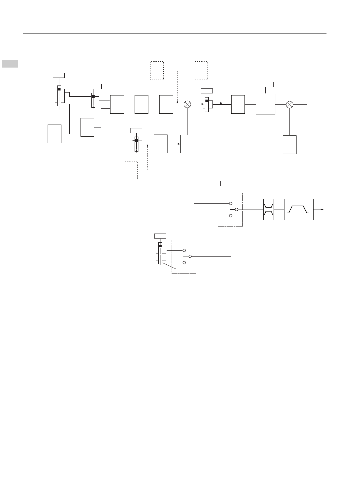
Configuration Mode - Complete menu (FULL)
200-
300-
400-
500-
600-
700-
PID diagram
Reference
channel 1
Modbus
Remote display
Integrated display
with Jog dial
Internal PID
reference value
59.11
401
Activation internal
PID reference value
59.05
234 preset PID
reference value
59.08
59.09
59.10
Preset PID
assignment
59.13
59.14
Analog terminal
PID feedback
PID reference
59.06
59.07
PID min/max
value reference
59.00
No
805
PID manual reference
PID error
806 804
PID reference
value ramp
59.12
PID feedback
scale factor
59.04
PID correction reverse
+
Yes
+
59.20
PID: Wake up threshold
Automatic
(1)
59.18
59.16
wake up level
No
PID auto/manual assignment
59.17
Manual
PID:
59.19
(LI)
Speed
reference
801
59-
PID gain
59.01
59.02
59.03
PID predictive speed
High speed
512.2
512.0
Low speed
+
+
59.15
deceleration ramp
(1)
Acceleration
No
Anolog terminal
Integrated display
with Jog dial
Preset
speed
84 EAV94277 11/2020
Page 85
Configuration Mode - Complete menu (FULL)
200-
300-
400-
500-
600-
700-
Code Name/Description Adjustment range Factory setting
500-
59-
59.00
59.01
59.02
59.03
59.04
Function menu (continued)
PID menu
M PID feedback assignment
00
01
v Not assigned.
v Analog terminal. Choice not possible if 401 is set to 01.
M PID proportional gain
Visible only if [PID feedback assignment 59.00 is not set to 00.
M PID integral gain
Visible only if [PID feedback assignment 59.00 is not set to 00.
M PID derivative gain
Visible only if [PID feedback assignment 59.00 is not set to 00.
M PID feedback scale factor
This parameter gives the relation between process range and feedback range.
Visible only if [PID feedback assignment 59.00 is not set to 00.
00
0.01 to 100 1
0.01 to 100 1
0.00 to 100.00 0.00
0.1 to 100.0 1.0
59.05
59.06
M Activation internal PID reference value
Visible only if [PID feedback assignment 59.00 is not set to 00.
00
01
v No
v Yes
M 2 preset PID assignment
Visible only if [PID feedback assignment 59.00 is not set to 00.
00
L1H
L2H
L3H
L4H
LUH
Parameter that can be modified during operation or when stopped.
v None
v L1h
v L2h
v L3h
v L4h
v LUH
00
00
EAV94277 11/2020 85
Page 86
Configuration Mode - Complete menu (FULL)
200-
300-
400-
500-
600-
700-
Code Name/Description Adjustment range Factory setting
500-
59-
59.07
59.08
59.09
59.10
00
L1H
L2H
L3H
L4H
LUH
Function menu (continued)
PID menu (continued)
M 4 preset PID assignment
Visible only if [PID feedback assignment 59.00 (page 85) is not set to 00.
v None
v L1h
v L2h
v L3h
v L4h
v LUH
Before assigning 4 preset PID assignment 59.07, 2 preset PID assignment 59.06 (page 85
assigned.
M 2 preset PID reference value
Visible only if [PID feedback assignment 59.00 (page 85) and 2 preset PID assignment 59.06 (page 85)
are not set to 00.
M 3 preset PID reference value
Visible only if [PID feedback assignment 59.00 (page 85) and 4 preset PID assignment 59.07
(page 86
M 4 preset PID reference value
Visible only if [PID feedback assignment 59.00 (page 85), 2 preset PID assignment 59.06 and
4 preset PID assignment 59.07 (page 86
) are not set to 00.
00
) must be
0 to 100% 25%
0 to 100% 50%
0 to 100% 75%
) are not set to 00.
59.11
59.12
59.13
59.14
59.15
M Internal PID reference value
Visible only if [PID feedback assignment 59.00 (page 85)is not set to 00 and Activation internal PID
reference value 59.05 (page 85
) is set to 01 or Reference channel 1 401 (page 72) is set to 163.
M PID reference value ramp
Visible only if [PID feedback assignment 59.00 (page 85) is not set to 00.
M PID min value reference
Visible only if [PID feedback assignment 59.00 (page 85) is not set to 00.
M PID max value reference
Visible only if [PID feedback assignment 59.00 (page 85) is not set to 00.
M PID predictive speed
This parameter allows direct attainment of a set speed reference.
Visible only if [PID feedback assignment 59.00 (page 85
Parameter that can be modified during operation or when stopped.
0 to 100% 0%
0 to 99.9 s 0 s
0 to 100% 0%
0 to 100% 100%
0.1 to 400 Hz nO
) is not set to 00.
86 EAV94277 11/2020
Page 87

Configuration Mode - Complete menu (FULL)
200-
300-
400-
500-
600-
700-
Code Name/Description Adjustment range Factory setting
500-
59-
501.4
59.16
Function menu (continued)
PID menu (continued)
M Acceleration 2
This parameter only can be activated when the system is starting.
Second acceleration ramp time, adjustable from 0.1 to 999.9 s.
The time required to accelerate from 0 to Rated motor frequency 306 (page 65
is compatible with the inertia being driven.
Visible only if PID feedback assignment 59.00 (page 85
00
01
02
03
(page 86
M PID correction reverse
This parameter will reverse the internal error value of PID system.
v No , no negative speed
v Yes, no negative speed
v No, allow negative speed
v Yes, allow negative speed
Visible only if:
PID feedback assignment 59.00 (page 85
Negative speed possible only if
Low speed 512.0 is set to 00
Reverse inhibition 404 is set to 00
) are not set to 00.
0.0 to 999.9 s 5.0 s
). M ake sure that th is valu e
) and PID predictive speed 59.15
00
) is not set to 00
59.17
59.18
M PID auto/manual assignment
At state 0 of input, PID is active.
At state 1 of input, manual run is active.
00
L1H
L2H
L3H
L4H
LUH
v No
v L1h: LI1 active high
v L2h: LI2 active high
v L3h: LI3 active high
v L4h: LI4 active high
v LUh: LIU active high
Visible only if PID feedback assignment 59.00 (page 85
M PID manual reference
This parameter can disable the PID and enable the standard manual reference.
00
01
02
Parameter that can be modified during operation or when stopped.
v No
v Anolog terminal
v Integrated display with Jog dial
Visible only if PID feedback assignment 59.00 (page 85
87
) are not set to 00.
00
) is not set to 00.
00
) and PID auto/manual assignment 59.17 (page
EAV94277 11/2020 87
Page 88
Configuration Mode - Complete menu (FULL)
200-
300-
400-
500-
600-
700-
Code Name/Description Adjustment range Factory setting
500-
59-
512.1
59.19
59.20
Function menu (continued)
PID menu (continued)
M Low speed operating time
A motor stop is requested automatically following a defined period of operation at Low speed 512.0
(page 100
command is still present.
Note: 00 value corresponds to an unlimited period.
Visible only if PID feedback assignment 59.00 (page 85
M PID: wake up level
If PID functions and Low speed operating time512.1 are set at the same time, the PID regulator may try to
set a speed lower than Low speed 512.0. This will result in unwanted operations consisting of starting,
running at Low speed 512.0, stopping and so on. Parameter PID: w ake u p leve l 59.19 can b e used to se t
a minimum PID error threshold to restart after a prolonged stop below Low speed 512.0.
Visible only if PID feedback assignment 59.00 (page 85
(page 100
M PID: Wake up threshold
If PID correction reverse 59.16 (page 87) is set to nO, this parameter can be used to set the PID feedback
threshold. Following a stop caused by exceeding the maximum time at low speed 512.1, the PID regulator
is reactivated (wake-up) when this threshold is exceeded.
If 59.16 is set to 01, the PID regulator is reactivated (wake-up) when this threshol d is exceeded, following
a stop caused by exceeding the maximum time at low speed 512.1.
). The motor restarts if the frequency reference is greater than Low speed 512.0 and if a run
) are not set to 00.
0.1 to 999.9 s 00
) is not set to 00.
0 to 100% 0%
) and Low speed operating time 512.1
0 to 100% 0%
Visible only if PID feedback assignment 59.00 (page 85
(page 100
Parameter that can be modified during operation or when stopped.
) is not set to 00.
) and Low speed operating time 512.1
88 EAV94277 11/2020
Page 89
Configuration Mode - Complete menu (FULL)
Code Name/Description Adjustment range Factory setting
59.21
59.22
59.23
59.24
59.25
59.26
510-
M Sleep offset threshold
M PID feedback supervision threshold
M PID supervision function time delay
M Maximum frequency detection Hysteresis
M PID feedback supervision
00
01
04
v Alarm ignore
v Freewheel stop
v Fall back speed
M Fall back speed
PUMP SUB-MENU
0 ~ 512.2 (*0)
0 - 100% (*0)
0 - 300s (*0)
0~ high speed frequency (*0).
0 to 512.2 0 Hz
0 - 100% 0 (No)
0 - 300s
0 to 512.2 0 Hz
0 to 512.2 0 Hz
0 s
00
207
208
209
210
211
M Application Overload time delay
0-100 s 5 s
v Overload detection time delay
v Value of zero will inactivate the function and make other parameters unaccessable.
v 0 - 100s (*0)
M Application Overload threshold
The overload detection threshold is expressed as a percentage of [Nominal motor current] (nCr). To activate
the function, this value must be smaller than the limit current.
M Time delay before automatic start for the
70 - 150 % In 90%
0-6 min. 0 min.
overload fault
If [Overload fault management] (604.2) = [alarm ignore], then this parameter will be unaccessable.
Minimum time allowed between overload detection and any automatic restart.
To perform an automatic restart, the value of the [Automatic restart] (602.1) must exceed this parameter by
at least one minute.
M Application underload time delay
Value of zero will inactivate the function and make other parameters unaccessable.
M Application Underload threshold
The underload threshold at zero frequency is expressed as a percentage of rated motor torque.
0-100 s 0 s
20%-100% 60%
EAV94277 11/2020 89
Parameter that can be modified during operation or when stopped.
Page 90
Configuration Mode - Complete menu (FULL)
Code Name/Description Adjustment range Factory setting
212
510.0
510.1
510.2
510.3
00
01
M Underload fault duration
Minimum time allowed between underload detection and any automatic restart.
To perform an automatic restart, the value of the [Automatic restart] (602.1) mus t ex cee d th is p ara me ter
by at least one minute.
M Selecting operating mode
v No: single frequency conversion mode
v Yes: single frequency conversion combined with auxiliary pump mode
If 510.0 = [01], digital output LO will automatically assign value pump switching.
M Starting frequency of the auxiliary pump
The auxiliary pump will start if this frequency is exceeded and after the pump start time delay (value of
510.2).
M Time delay before starting auxiliary pump
This time avoids the effects of transient pressure fluctuations and so avoids vibrations generated during
pump starting and stopping
.
M Auxiliary pump ramp reaching
0-6 min. -
0-308 parameter
value
0-999.9s 2 s
0-999.9s 2 s
512.2
parameter value
510.4
510.5
510.6
510.7
510.8
510.9
M Auxiliary pump stop frequency
The auxiliary pump will stop below this frequency after the auxiliary pump stop delay (value of 510.5).
M Auxiliary pump stop time delay
This time avoids the effects of transient pressure fluctuations and so avoids vibrations generated during
pump starting and stopping
.
M Auxiliary pump stop ramp
M Zero flow detection period
Function inactive if value is 0.
M Zero flow detection activation threshold
Below this threshold function activated if 510.7 value >0 and the auxiliary pump is stopped.
M Zero flow detection offset
0-308 parameter
value
0-999.9s 2 s
0-999.9s 2 s
0-20 min. 0 min.
0-400Hz 0Hz
0-400Hz 0Hz
0Hz
90 EAV94277 11/2020
Page 91

Configuration Mode - Complete menu (FULL)
Variable pump
ATV310
Pressure sensor
0-20 mA
4-20 mA
0+5 V
0+10 V
Architecture of the pumping installation
Single variable mode - 1 single variable speed pump
Enter the values given on the motor rating plate in the Motor control menu 300-
First level adjustment parameters
501.0 Acceleration: 0.7 s
501.1 Deceleration: 0.7 s
512.0 Low speed: 30 Hz
512.2 high-speed: 60 Hz
Analog input menu AIt
204.0 Scale of analog input AI1: 0-20 mA
Motor control menu drC
311 Nominal motor slip: 0 Hz
313 Frequency loop gain: 70%
310 IR compensation: 0%
Application functions menu FUn
202 2-wire type control: LEL
PI sub-menu
59.00 Assignment of the PI function feedback: AI1
59.01 PI regulator proportional gain: 5.00
59.02 PI regulator integral gain: 8.00
59.11 Internal PI regulator reference: 39%
59.19 Restart error threshold: 40%
59.25 Supervision of the PI regulator function: LFF
59.22 PI feedback supervision threshold: 17%
59.23 PI feedback supervision function time delay: 1 s
59.26 Fallback speed: 50 Hz
Pump sub-menu PMP
510.7 Zero flow detection: 1 min
510.8 Zero flow detection activation threshold: 50 Hz
510.9 Zero flow detection offset: 5 Hz
512.1 Sleep threshold operating time: 3 s
59.15 Quick start threshold: 25 Hz
59.21 Sleep threshold offset: 10 Hz
Automatic DC injection sub-menu AdC
512.0 Automatic DC injection assignment: nO
Automatic restart function Atr
602.0 Automatic restart: YES
Fault menu 600-
208 Overload threshold: 11%
209 Time delay before automatic start for the overload fault: 1
59.24 Frequency hysteresis reached: 2 Hz
EAV94277 11/2020 91
Page 92
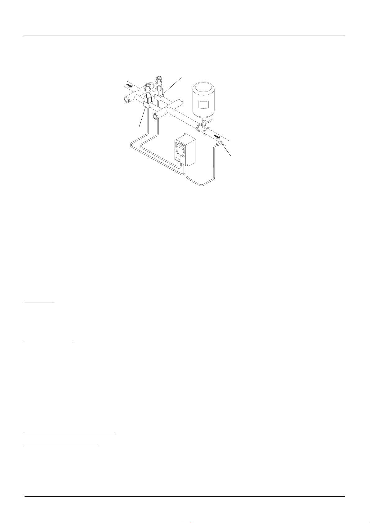
Configuration Mode - Complete menu (FULL)
Variable pump
ATV310
Fixed speed auxiliary pump
Pressure
sensor
0-20 mA
4-20 mA
0+5 V
0+10 V
Single variable with auxiliary pump mode - 1 variable speed pump (variable pump) and one fixed speed
pump (auxiliary pump)
The auxiliary pump is controlled by the ATV310 via logic output LO.
Enter the values given on the motor rating plate in the Motor control menu 300-
First level adjustment parameters
501.0 Acceleration: 0.1 s
501.1 Deceleration: 0.1 s
512.0 Low speed: 35 Hz
Analog input menu 204-
204.0 Scale of analog input AI1: 0-20 mA
Motor control menu 300-
311 Nominal motor slip: 0 Hz
313 Frequency loop gain: 70%
310 IR compensation: 0%
Application functions menu FUn
202 2-wire type control: 00
PI sub-menu
59.00 Assignment of the PI function feedback: 01
59.01 PI regulator proportional gain: 5.00
59.02 PI regulator integral gain: 8.00
59.11 Internal PI regulator reference: 51%
59.19 Restart error threshold: 42%
Pump sub-menu PMP
510.0 Selecting the operating mode: 01 (Yes)
510.1 Starting frequency of the auxiliary pump: 49 Hz
510.2 Time delay before starting the auxiliary pump: 1 s
510.3 Ramp for reaching the nominal speed of the auxiliary pump: 1 s
510.4 Stopping frequency of the auxiliary pump: 39.6 Hz
510.5 Time delay before the auxiliary pump stop command: 1 s
510.6 Ramp for stopping the auxiliary pump: 1 s
510.7 Zero flow detection: 1 min
510.8 Zero flow detection activation threshold: 42 Hz
510.9 Zero flow detection offset: 2 Hz
512.1 Sleep threshold operating time: 5 s
59.21 Sleep threshold offset: 3 Hz
206.1 Assignment as logic/analog output PMP
Automatic DC injection sub-menu
512.0 Automatic DC injection assignment: 00
Automatic restart function
602.0 Automatic restart: 01 (active)
Fault menu 600-
210 Underload function time delay 5 s
211 Underload threshold: 59%
212 Time delay before automatic restart for the underload fault: 1
92 EAV94277 11/2020
504-
602-
Page 93

Configuration Mode - Complete menu (FULL)
KM1
KM1
U/T1
M1
3
V/T2
W/T3
R/LI
AI1
COM
+5 V
LO+
LI1
LI2
LI3
LI4
+24 V
LO-
S/L2
T/L3
(1)
R1A
R1C
ATV310
M2
3
3-phase supply
380V...460V
Variable
pump
Pressure sensor
0-20 mA
4-20 mA
0+5 V
0+10 V
Auxiliary pump
3-phase supply
380V...460V
Connection diagram
(1) Fault relay contacts, for remote indication of the drive status.
Note: Fit interference suppressors to all inductive circuits near the drive or connected to the same circuit (relays, contactors, solenoid valves,
etc.).
Note: This wiring example is in source using internal supply.
EAV94277 11/2020 93
Page 94

Configuration Mode - Complete menu (FULL)
LPI + 3 %
LPI
LPI - 2 %
HSP
HSP - AP0
LFF
MPI = LFF
MPI = YES
< tPI tPI
PI feedback
Motor speed
End-of-time delay
Fallback mode
defined by 59.25
PI feedback supervision (59.25)
Used to define the operating mode in the event of detection of a PI feedback lower than the limit set.
Once the variable pump is running at maximum speed (h igher than
supervision threshold
the supervision threshold
-
59.25 = 01:
The drive will perform a freewheel stop.
-
59.25 = 04:
The drive will run at a fixed frequency
In both cases the drive reverts to PI regulation mode as soon as the PI feedback is higher than the supervision threshold
In single variable with auxiliary pump mode (
operating.
59.22 – 2%, a time delay tPI is launched. If at the end of this time delay the value of the PI feedback is still lower than
59.22 + 3%, the drive switches to fallback mode as defined by parameter 59.25.
59.26 and will display fault code --12.
510.0 = 01), the PI feedback supervision function is only active when both pumps are
512.2 – 59.24) and at the same time the PI feedback is lower than the
59.22 + 3%.
94 EAV94277 11/2020
Page 95
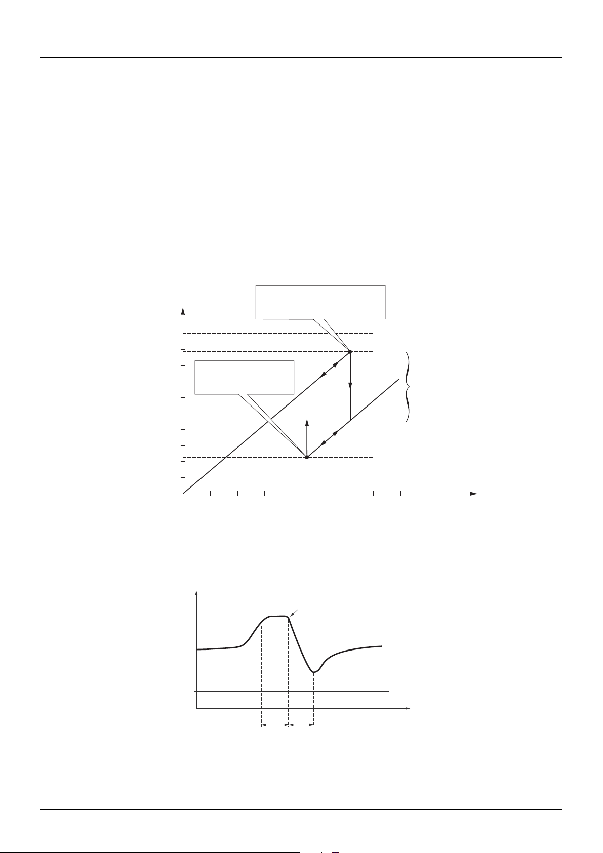
Configuration Mode - Complete menu (FULL)
Frequency of the
variable pump
Auxiliary pump starting
Auxiliary pump
stopping
Frequency
corresponding to the
auxiliary pump flow
rate
512.2
Starting frequency
510.1
Stopping frequency
510.4
Flow rate of the installation
212.2
510.1
510.4
510.2 510.3
512.0
0
t
Frequency of the
variable pump
Auxiliary pump starting
512.0
510.4
510.1
212.2
510.2
510.3
Pump submenu PMP
The principal objective is to control a complete pumping installation using a single drive by providing constant pressure whatever the flow
rate.
The system is operated using an auxiliary fixed speed pump, and one variable speed pump, which is unable to provide the full flow range
required on its own. A PI regulator is used for drive control. The pressure sensor provides system feedback.
The variable speed pump is called a variable pump.
The fixed speed pump is called an auxiliary pump.
Selecting the operating mode
The ATV310 offers 2 operating modes:
• Single variable mode: 1 single variable speed pump (variable pump).
• Single variable with auxiliary pump mode: 1 variable speed pump (variable pump) and one fixed speed pump (auxiliary pump).
Control of the auxiliary pump
The PI regulator output (frequency reference of the variable pump) is used to control starting or stopping of the auxiliary pump with
hysteresis, as shown in the figure below:
When the frequency exceeds the starting threshold (
fluctuations. If after this time delay, the frequency remains higher than the starting threshold, the auxiliary pump is started. When the start
command is sent, the variable pump will go from its current speed reference to the auxiliary pump stopping frequency (
ramp (
510.3) that equals the time taken for the auxiliary pump to reach its nominal speed. Parameter rOn is used to minimize the booster
effect on starting the auxiliary pump.
EAV94277 11/2020 95
510.1), a time delay (510.2) is launched to avoid the effects of transient flow
510.4) following a
Page 96
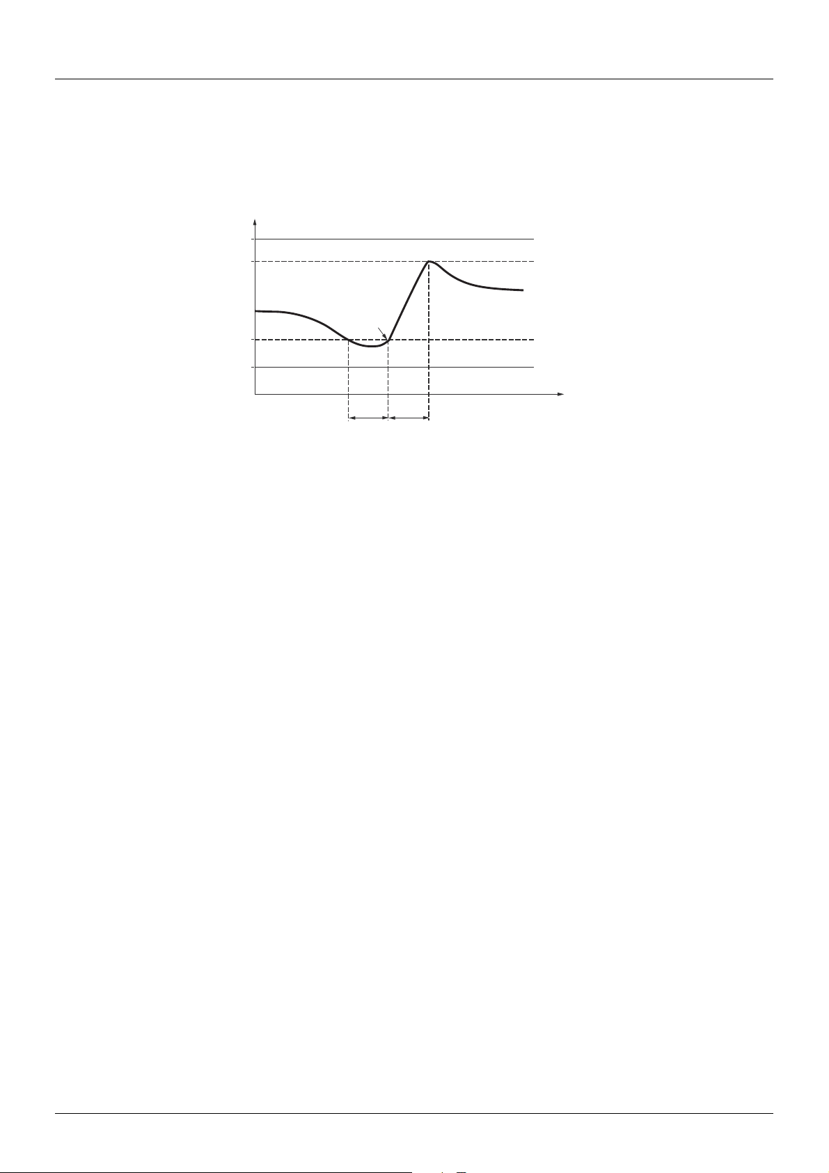
Configuration Mode - Complete menu (FULL)
Frequency of the
variable pump
Auxiliary pump
stopping
512.2
510.1
510.4
512.0
510.2
510.6
When the frequency is lower than the stopping threshold (510.4), a time delay is launched (510.2) to avoid the effects of transient flow
fluctuations. If after this time delay, the frequency remains lower than the stopping threshold, the auxiliary pump is stopped. When the stop
command is sent, the variable pump will go from its current speed reference to the auxiliary pump starting frequency (510.1) following a
ramp (510.6) that equals the auxiliary pump stopping time. Parameter 510.6 is used to minimize the booster effect on stopping the
auxiliary pump.
512.2
510.1
510.4
512.0
510.2
t
510.6
96 EAV94277 11/2020
Page 97
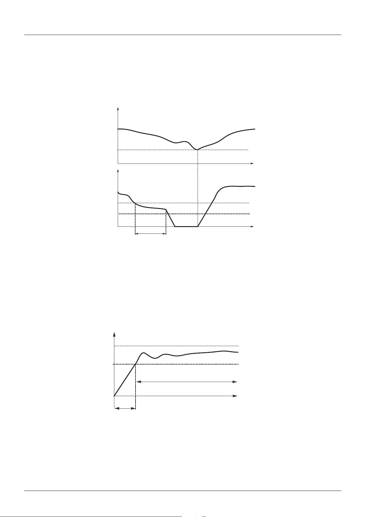
Configuration Mode - Complete menu (FULL)
PI feedback
Motor frequency
Low speed or speed threshold
operating time
59.20
512.0+59.21
512.0
512.1
Frequency of the
variable pump
512.2
59.15
510.4
"Sleep" function/"Wake-up" function
This function is used to stop the variable pump when there is zero flow (auxiliary pump stopped). In this case, if the frequency of the variable
pump is lower than the "sleep" threshold (512.0 + 59.21), a time delay (512.1) is launched. If, after this time delay, the frequency
remains lower than threshold 512.0 + 59.21, the variable pump then stops. The installation is in "sleep" mode.
To switch to "wake-up" mode, the pressure feedback must drop to below the "wake-up" threshold 59.20. The vari able pum p is t hen star ted.
59.20
t
512 .0 + 59.21
512 .0
512 .1
t
Quick start function
The quick start function can be used to overcome problems linked to high 59.01 and 59.02 gains (instability on starting). The drive
accelerates until it reaches the quick start threshold 59.15 following a ramp 510.4. Once the threshold has been reached, the PI regulator
is activated.
512.2
59.15
EAV94277 11/2020 97
501.0
t
Page 98

Configuration Mode - Complete menu (FULL)
510.8
512.0 + 510.9
510.7
512.0
t
t
510.7
PI feedback
PI error
Frequency reference
510.8
512.0+510.9
512.0
510.7
510.7
t
t
512.2
512.0
510.8
510.7 512.1
512.0 + 510.9
PI feedback
Frequency reference
Sleep threshold
512.0 + 59.21
512.2
510.8
512.0+510.9
512
510.7
512.1
Zero flow detection
This function is only active when the auxiliary pump is stopped and the motor frequency is below threshold 510.8.
This function is used in applications where zero flow cannot be detected by the sleep function alone. It forces the drive frequency reference
to 512.0 + 510.9 periodically (at each time interval 510.7) in order to test for zero flow.
• If the request is still present, the PI error increases, causing the drive to restart.
• If the request is no longer present (zero flow), the PI error will not increase.
• Set the sleep function so that the drive switches to sleep mode when zero flow is detected (510.9 y 59.21).
98 EAV94277 11/2020
Page 99

Configuration Mode - Complete menu (FULL)
200-
300-
400-
500-
600-
700-
Code Name/Description Adjustment range Factory setting
500-
511-
511.0
511.1
00
L1H
L2H
L3H
L4H
LUH
L1L
L2L
L3L
L4L
LUL
Function menu (continued)
CURRENT LIMITATION MENU
M 2nd current limitation commutation
Assignment
v Function inactive
v L1H: LI1 active high
v L2H: LI2 active high
v L3H: LI3 active high
v L4H: LI4 active high
v LUH: LIU active high
v L1L: LI1 active low
v L2L: LI2 active low
v L3L: LI3 active low
v L4L: LI4 active low
v LUL: LIU active low
If the assigned input is at 0, the first current limitation is active.
If the assigned input is at 1, the second current limitation is active.
See LI assignment information (page 53
M Current limitation
First current limitation.
00
).
Determined by
0.25 to 1.5 In (1)
drive rating and
dual rating
511.2
NOTICE
OVERHEATING AND DAMAGE TO THE MOTOR
Depending on the settings of this parameter, the error response to detected errors is disabled or the transition to
the operating state Fault is suppressed if an error is detected.
• Verify that the settings of this parameter do not result in equipment damage.
• Implement alternative monitoring functions for disabled monitoring functions.
Failure to follow these instructions can result in equipment damage.
M Current limitation 2
Second current limitation.
This function allows reduction of the drive current limit.
Visible only if 2nd current limitation commutation 511.0 (page 99
0.25 to 1.5 In (1)
) is not set to 00.
Determined by
drive rating and
dual rating
NOTICE
OVERHEATING AND DAMAGE TO THE MOTOR
Depending on the settings of this parameter, the error response to detected errors is disabled or the transition to
the operating state Fault is suppressed if an error is detected.
• Verify that the settings of this parameter do not result in equipment damage.
• Implement alternative monitoring functions for disabled monitoring functions.
Failure to follow these instructions can result in equipment damage.
(1) In = rated drive current
EAV94277 11/2020 99
Parameter that can be modified during operation or when stopped.
Page 100

Configuration Mode - Complete menu (FULL)
200-
300-
400-
500-
600-
700-
Code Name/Description Adjustment range Factory setting
500-
512-
512.0
512.1
Function menu (continued)
Speed limit menu
M Low speed
Motor frequency at minimum reference.
M Low speed operating time
Following operation at Low speed 512.0 for a defined period, a motor stop is requested automatically.
The motor restarts if the reference value is greater than Low speed 512.0 and if a run command is still
present.
Note: 00 corresponds to an unlimited period.
0 Hz to 512.2
parameter value
0.1 to 999.9 s 00
0 Hz
100 EAV94277 11/2020
 Loading...