

Schlage WRI-IN-12VDC,AUWRI-IN-12VDC Installation Instructions Manual

Wireless Access
INSTALLATION INSTRUCTIONS
WIRELESS READER
INTERFACE - INDOOR
(WRI-IN-12VDC or AUWRI-IN-12VDC)
The most current version of this document is available for download at:
http://www.ir-swa.com
P/N: M053-014-C

Wireless Access
Schlage
Ingersoll Rand Security Technologies
245 W. Roosevelt Road, Building 7, Suite 48
West Chicago, IL 60185
main: 800-313-2962 (630-876-5680)
technical support: 866-322-1237
fax: 630-293-4257
web: ir-swa.com
Copyright © 2003-2006 Ingersoll Rand, all rights reserved.
No part of this document can be reproduced, transmitted, or transcribed in any form by electrical, mechanical, optical, manual, or
otherwise without the prior written consent of Ingersoll Rand. Ingersoll Rand reserves the right to alter or revise the content of
this document as needed to support future product revisions, without obligation to notify any persons of specific changes.
The use of trademarks, trade names, or other product identification is solely for reference purposes. All other product brand
names are trademarks or registered trademarks of their respective holders.
Ingersoll Rand believes the information in this document to be accurate and reliable. Ingersoll Rand does not guarantee results
from the use of this information. Ingersoll Rand assumes no responsibility, obligation, or liability for the information presented in
this document.
Ingersoll Rand Security Technologies
245 W. Roosevelt Road, Bldg 7, Suite 48, West Chicago, IL 60185 / (800) 313-2962 / (630) 293-42 57 fax
P/N: M053-014-C www.ir-swa.com Page 2 of 18

Wireless Access
INSTALLATION INSTRUCTIONS
Wireless Reader Interface - Indoor (WRI-IN)
NOTE: These instructions are for installing the Wireless Reader Interface - Indoor (WRI-IN-12VDC), a component
of a Schlage Wireless Access System. AUWRI-IN-12VDC is an Australian version of the indoor wireless reader
interface.
In this manual, WRI-IN refers to either a WRI-IN-12VDC or an AUWRI-IN-12VDC model.
After completing this installation refer to the “Configuring and Operating the Schlage Wireless Access System”
manual.
1. Schlage Wireless Access System Components...............................................................................................4
2. Installing the WRI-IN......................................................................................................................................5
Table of Contents
1.1 Overview .......................................................................................................................................................4
1.2 Wireless Reader Interface - Indoor (WRI-IN) Components & Sales Models................................................5
2.1 Tools – Hardware Required ...........................................................................................................................5
2.2 Determining the Best WPIM and WRI-IN Locations....................................................................................6
2.3 Mounting the WRI-IN ...................................................................................................................................7
2.4 Getting Wires In & Out of the WRI-IN.........................................................................................................8
2.5 Wiring the WRI-IN to its Access Control Peripherals...................................................................................9
3. WRI-IN Cable/Wire Specifications..............................................................................................................15
4. Contacting Technical Support......................................................................................................................16
5. FCC Compliance, ACA Compliance & Warnings......................................................................................17
5.1 FCC Compliance .........................................................................................................................................17
5.2 ACA Compliance.........................................................................................................................................17
5.3 UL Compliance............................................................................................................................................17
5.4 Warnings......................................................................................................................................................17
6. Revision History.............................................................................................................................................18
Ingersoll Rand Security Technologies
245 W. Roosevelt Road, Bldg 7, Suite 48, West Chicago, IL 60185 / (800) 313-2962 / (630) 293-42 57 fax
P/N: M053-014-C www.ir-swa.com Page 3 of 18
Wireless Access
1. Schlage Wireless Access System Components
1.1 Overview
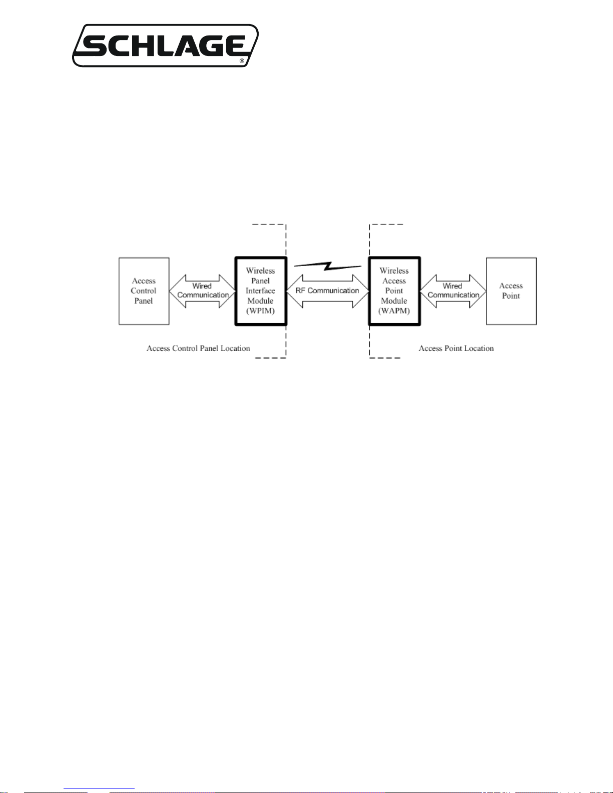
Every access control system that uses Schlage Wireless Access contains two different types of modules
(Figure 1-1):
• at least one Wireless Panel Interface Module (WPIM), and
• at least one Wireless Access Point Module (WAPM)
Figure 1-1 – Schlage Wireless Access System Block Diagram
The Schlage Wireless Access product line contains several different expressions of each module.
The WPIM is wired to the access control panel and ideally is installed very close to the access control
panel. The WPIMs installation location is determined by the location of the WAPMs with which it will
communicate using RF.
The WAPM is installed at the access point where access will be controlled and/ or m onitored. De pe nding
on the application and which WAPM is used, some wiring at the access control point may be required.
Regardless of which WPIM or WAPM module is used, the communication link between the WPIM and
WAPM is always RF.
This manual describes the installation of a Wireless Reader Interface - Indoor (WRI-IN-12VDC or
AUWRI-IN-12VDC) which is a WAPM.
Ingersoll Rand Security Technologies
245 W. Roosevelt Road, Bldg 7, Suite 48, West Chicago, IL 60185 / (800) 313-2962 / (630) 293-42 57 fax
P/N: M053-014-C www.ir-swa.com Page 4 of 18
Wireless Access
1.2 Wireless Reader Interface - Indoor (WRI-IN) Components & Sales
Models
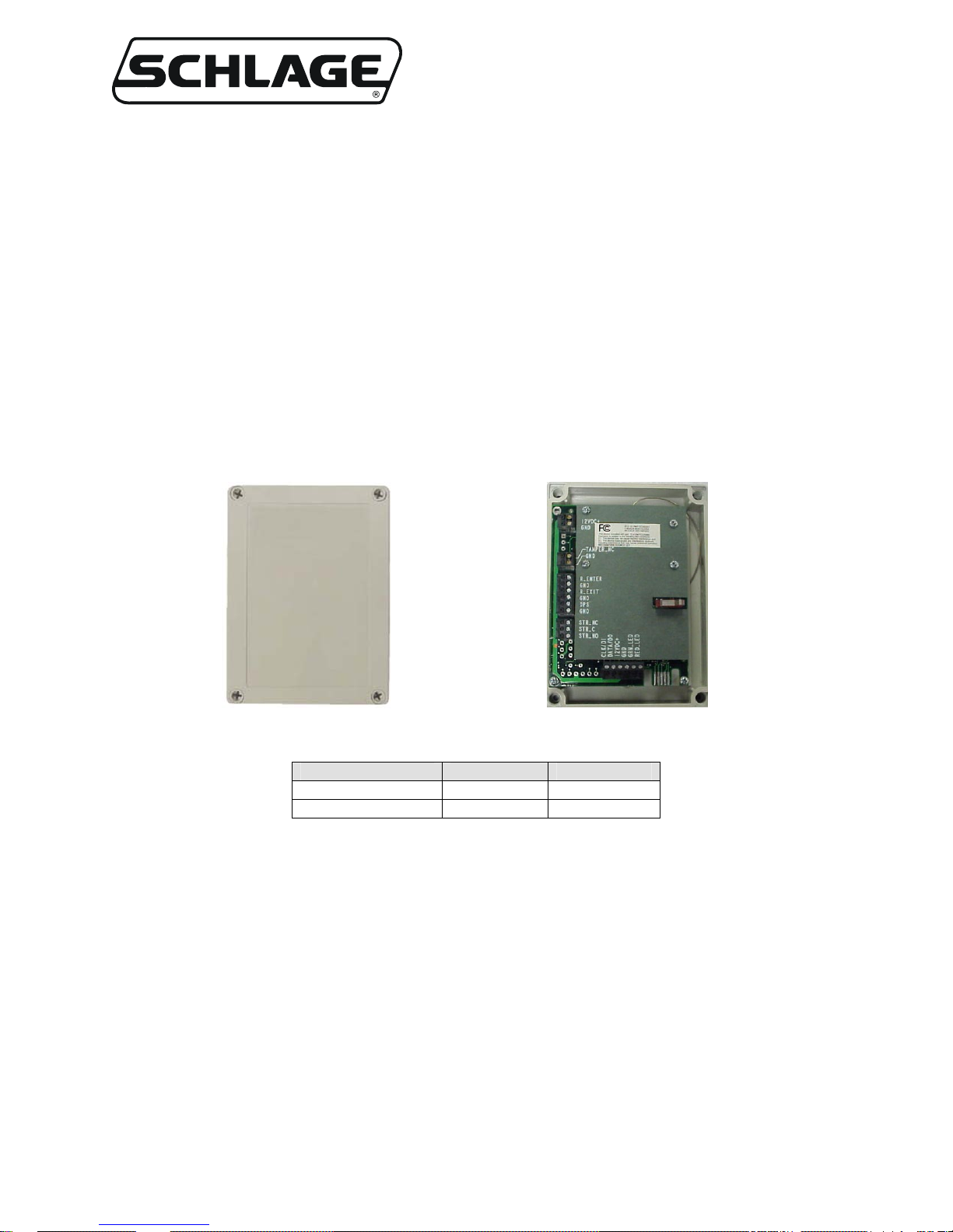
The WRI-IN (Figure 1-2 & Figure 1-3) includes the following components:
• a reader/keypad connector
• strike relay connector
• door position input
• request to exit input
• request to enter input
• ta mper input & tamper switch
• flash programming port
• RF Transceiver
Figure 1-2 – Front of the WRI-IN
MODEL MOUNTING LOCATION
WRI-IN-12VDC surface indoor
AUWRI-IN-12VDC surface indoor
Table 1-1- WRI-IN Sales Model Table
2. Installing the WRI-IN
2.1 Tools – Hardware Required
• Hammer
• 9/32” & 3/4” drill bits (the size will depend on the mounting fasteners used)
• Flat and Phillips head screwdrivers (1/8” wide flat blade for screw terminals)
• Pencil (#2 lead)
• Mounting Kit, provided, including four #8 X 2 ½” screws, four heavy-duty anchors, four washers and
four 1” high round spacers
Figure 1-3 – Inside the WRI-IN
Ingersoll Rand Security Technologies
245 W. Roosevelt Road, Bldg 7, Suite 48, West Chicago, IL 60185 / (800) 313-2962 / (630) 293-42 57 fax
P/N: M053-014-C www.ir-swa.com Page 5 of 18

Wireless Access
2.2 Determining the Best WPIM and WRI-IN Locations
Proper selection of WPIM and WRI-IN module mounting locations insures reliable RF communications.
The WPIM manual contains a section for determining the best location for the WPIM.
The maximum distance between WPIM and a WRI-IN is 200’ horizontally when installed inside a
building on the same floor that uses normal building construction materials. Never locate the WRI-IN
and WPIM more than one (1) floor apart. If on different floors, limit the maximum horizontal distance to
100’. Do not locate on different floors if the building’s floors use concrete over metal construction. The
maximum distance is 1000’ for a line of sight installation.
This section provides additional application specific help and guidelines to select the best mounting
location for the WRI-IN Transceiver Cont rol B ox:
• Mount the WRI-IN Transceiver Control Box inside the protected area.
• Mount the WRI-IN Transceiver Control Box on the wall, at least 55” from the floor
• Mount the WRI-IN Transceiver Control Box within 500’ cable feet of the Card Reader or other input
device
• Mount the WRI-IN Transceiver Control Box within 500’ cable feet of the Strike.
• A WRI-IN must, in all directions (sides, top, bottom, and back), have a minimum 1” separation from
any metal surface. Therefore if the WRI-IN must be mounted on a metal surface, though not
recommended, the supplied 1” spacers must be used.
NOTE: A WRI-IN located with a substantial steel barrier intervening between it and the WPIM
may require alternate WRI-IN and/or WPIM placement in order to ensure reliable RF
communications. In these applications, mount the WPIM remote from the access control panel.
Choose the WPIM or the WPIM’s Remote Antenna location to prevent “shadowing” of the WRIIN from WPIM radio transmissions.
Ingersoll Rand Security Technologies
245 W. Roosevelt Road, Bldg 7, Suite 48, West Chicago, IL 60185 / (800) 313-2962 / (630) 293-42 57 fax
P/N: M053-014-C www.ir-swa.com Page 6 of 18
 Loading...