

Schlage WRI400 Instructions Manual
*P516-100*
P516-100
WRI400
Wireless Reader Interface
Instructions for WRI 400
+
-
+
-
C
B+
1
+
+
1
1
GND
GND
IF RADIO BOARD PRESENT
NC
BATT
COIN CELL NOT NEEDED
NC
C
NO
C
NO
PRIMARY SIDE
BEEPER
BEEPER
ALARM
STRIKE
AUX
PWR/
SIDE UP
LINE
GND
RTE
GND
GND
111
1
RED
GRN
GND
DATA\D0
CLK\D1
GND
SWITCH INPUT
CLK\D1
DATA\D0
RED
GRN
READER1 READER2
TAMP2
TAMP1
DPS
RTX
GND
DEBUG
TAMPER
STATUS
RELAY
RX/TX
USB
+12V
+5V
LID
+3.3V
RX
TX
GND
OPEN
A-
1
1
1
1
1
1
1
1
23394075_C
SCHLAGE
LINK
RESET
TAMPER
GND
20
19
2
1
ICLK
IDAT
RB8
RB7
GND
VDD
MCLR
USB
AA
BATT
LINE
ALR_NC
ALR_C
ALR_NO
AUX
AUX
AUX
STR
STR
STR
RB+
TB+
TA-
RS485
12/24VDC
THIS
MOUNT
LED2
BATTERY_HOLDER1
R112
C61
U4
REL1
J3
J7
REL2
REL3
U5
TP25
TP24
TP23
TP22
TP21
J6
LED1
LED4
LED7
LED5
LED6
LED3
J18
J17
J13
LED8
LED9
C32
J9
J12
J11
J10
J8
S3
S2
S1
J5
J2
J1
Para el idioma español, navegue hacia www.allegion.com/us
Pour la portion française, veuillez consulter le site www.allegion.com/us

2 • Schlage • WRI400 user guide
Contents
Overview ........................................................................................................................... 3
Getting started ..................................................................................................................4
Install the WRI400 ............................................................................................................5
PIM400 and WRI400 location ....................................................................................... 5
Remote antenna............................................................................................................5
Antenna location and safety .......................................................................................... 5
Antenna grounding ........................................................................................................ 6
Terminate the coax whip at the WRI400 .......................................................................6
Outdoor gate applications .............................................................................................7
Elevator applications ..................................................................................................... 8
Weather-tight installation of the WRI400 .......................................................................9
Non weather-tight installation of the WRI400 ................................................................ 9
Mounting the WRI400 ...................................................................................................9
Wiring the WRI400 to access control peripherals .......................................................10
WRI400 Cable/wire specications...............................................................................10
Portal inputs ................................................................................................................12
Portal outputs .............................................................................................................. 13
Credential readers.......................................................................................................15
Power failure modes ...................................................................................................16
Handheld device (HHD) .................................................................................................. 17
Coupling with the HHD ................................................................................................ 17
Construction access mode .............................................................................................18
Link the WRI400 to a PIM400 ......................................................................................... 18
Reset to factory defaults ................................................................................................. 19
Test .................................................................................................................................19
Troubleshooting ..............................................................................................................20
Important things to know before calling technical service ........................................... 21
WRI400 LED reference ...................................................................................................22
FCC/IC statements ........................................................................................................23
UL294 Access Control Levels tested to: Destructive Attack - Level 1; Line Security - Level 1;
Endurance - Level 4; Standby Power - Level 1.
3 • Schlage • WRI400 user guide
Overview
The Schlage Wireless Reader Interface (WRI400) is an open architecture Wireless Access
Point Module (WAPM) designed to interface with third-party panels through a Panel Interface
Module (PIM400-TD2, PIM400-485) by using radio frequency (RF) communication.
• Interfaces credential readers and portal access control with third-party panels.
• May be used with up to two (2) credential readers that use wiegand or clock and data
outputs.
• Supports ve (5) optional inputs: Reader 1 Tamper and Reader 2 Tamper, Request to
Enter, Request to Exit and Door Position (Portal Status).
• Supports two (2) Form C, dry contact relays intended for strike and auxiliary outputs
(i.e., door installations with magnetic locks or strikes).
• Externally powered using a UL294 for UL, and ULC S318/ULC S319 for cUL listed Class
2 power supply (not included) capable of sourcing at least 500 mA @ 12 or 24 VDC,
(example: Schlage models PS902, PS904, PS906).
• Suitable for outdoor use, ambient temperature range -35C to +66C (-31F to +151F).
• The WRI400 is listed under UL294 as an access control system accessory.
• Access equipment manufactured and/or sold by Allegion LLC, is not rated for, or
intended for use in life safety installations. UL listed panic hardware must be used to
allow emergency exit from the protected area.
• The WRI400 has not been evaluated to UL325 or UL508.
• The ANT400 antennas have not been evaluated to UL294 and are not for use in
UL installations.
• This product has been evaluated for ULC-S319 Class I.
+
-
+
-
C
B+
1
+
+
1
1
GND
GND
IF RADIO BOARD PRESENT
NC
BATT
COIN CELL NOT NEEDED
NC
C
NO
C
NO
PRIMARY SIDE
BEEPER
BEEPER
ALARM
STRIKE
AUX
PWR/
SIDE UP
LINE
GND
RTE
GND
GND
111
1
RED
GRN
GND
DATA\D0
CLK\D1
GND
SWITCH INPUT
CLK\D1
DATA\D0
RED
GRN
READER1 READER2
TAMP2
TAMP1
DPS
RTX
GND
DEBUG
TAMPER
STATUS
RELAY
RX/TX
USB
+12V
+5V
LID
+3.3V
RX
TX
GND
OPEN
A-
1
1
1
1
1
1
1
1
23394075_C
SCHLAGE
LINK
RESET
TAMPER
GND
20
19
2
1
ICLK
IDAT
RB8
RB7
GND
VDD
MCLR
USB
AA
BATT
LINE
ALR_NC
ALR_C
ALR_NO
AUX
AUX
AUX
STR
STR
STR
RB+
TB+
TA-
RS485
12/24VDC
THIS
MOUNT
LED2
BATTERY_HOLDER1
R112
C61
U4
REL1
J3
J7
REL2
REL3
U5
TP25
TP24
TP23
TP22
TP21
J6
LED1
LED4
LED7
LED5
LED6
LED3
J18
J17
J13
LED8
LED9
C32
J9
J12
J11
J10
J8
S3
S2
S1
J5
J2
J1
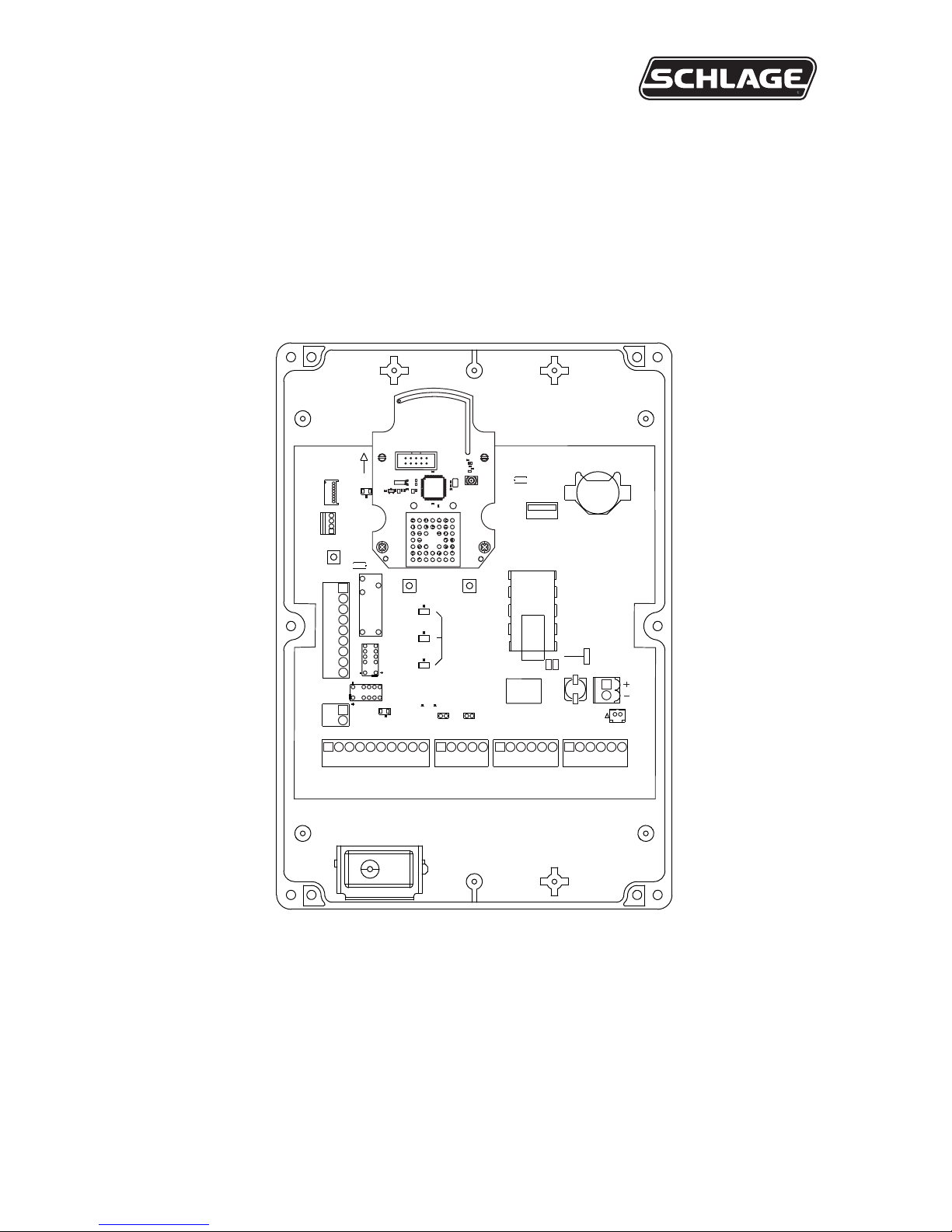
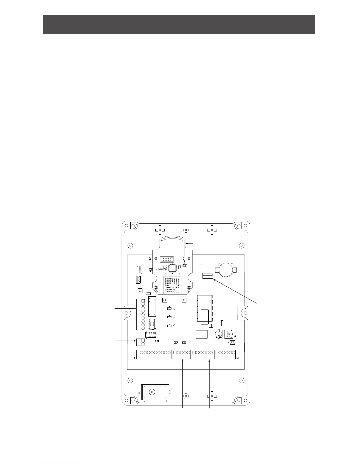
J2
Lid Tamper
Input Switch
J13
Switch Inputs
J10
Reserved
J5
USB
J7
Power
12 or 24
VDC
J17
Reader 1
J18
Reader 2
J6
Relay Outputs
Radio Board
SW1
Lid Tamper
Switch
4 • Schlage • WRI400 user guide
Getting started
Follow these steps when setting up a WRI400 with an access portal.
Before installing the Schlage WRI400, read all documentation for all products in the
installation.
1. Familiarize yourself with the information contained in this user guide.
2. To operate at optimum eciency, cable runs should be kept as short as possible.
3. Install the UL listed lock. See the installation guide that came with the lock or visit
www.allegion.com/us for more information to install Schlage locks.
4. Install the UL listed reader(s).
5. Install the WRI400.
6. Install a UL/ULC listed power supply for the WRI400 and the readers. The power
supply must be compatible with all components and must have the capacity to power the
WRI400 and the readers. (The WRI400 requires a power supply capable of sourcing at
least 500 mA @ 12 or 24 VDC.)
L If preferred, separate UL listed power sources for the WRI400 and the readers is
an acceptable alternative.
7. Install the Panel Interface Module (PIM400-TD2 or PIM400-485). See the installation
guide that came with the PIM or visit www.allegion.com/us for more information.
8. If a remote antenna is necessary, make sure it is properly located. As with all radio
systems, interference may be a problem. Refer to Remote antenna on page 5.
9. Make sure power is properly connected to all components in the system.
10. Link the WRI400 to its PIM400.
11. Test operation of the WRI400 with the access portal and UL listed access control
system.
L For compliance with UL 294, product must be used with a UL 294 Listed access control
panel or unit. For compliance with ULC S319, product must be used with a ULC S319
Listed access control panel or unit.
Save this user guide for future reference.
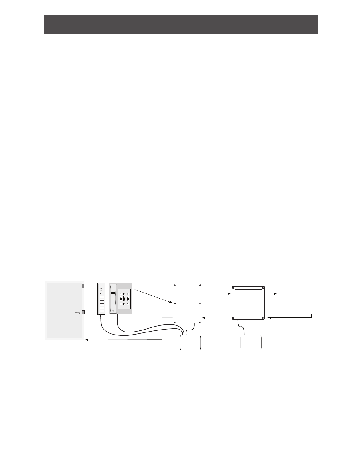
Typical Access Point Configuration
UL listed Access
Control Panel
(ACP)
WRI400
PIM400
Cre
d
en
t
i
a
l
s
Readers
RF Link
Door hardware
connections not shown.
Powe r
Supply
0 1
2 3
6 7
4 5
*
#
8 9
Powe r
Supply
UL listed exit
device or lock

5 • Schlage • WRI400 user guide
Install the WRI400
PIM400 and WRI400 location
Proper mounting location of the PIM400 and WRI400 ensures reliable RF communication.
Refer to the PIM400 user guide to determine the best location for the PIM400.
• Locate the WRI400 on the secured side of the access portal.
• For optimized radio performance, orient the WRI400 vertically with the radio board at the
top of the enclosure.
• The maximum distance indoors between a PIM400 and a WRI400 is 200 feet (61 meters)
when installed on the same oor in a building that uses normal construction materials.
• If a remote antenna is used with the WRI400, the maximum distance between the
WRI400 and the antenna is 15 cable feet (4.5 meters).
• Do not locate the WRI400 and remote antenna, or the PIM400 (and it’s remote antenna,
if used) on separate oors within a building. The maximum distance for a line-of-sight
installation is 1000 feet (305 meters)1.
• RF signals are diminished by walls, distance, metal objects or barriers. If metal walls or
metal mesh (stucco) walls are between the WRI400 and the PIM400, mount the PIM400
away from the UL listed access control panel. Use a Remote Antenna Module (ANT400)
with the PIM400, and choose a location that is free of obstacles which may cause a
reduction in signal power at the receiver.
The distance between the PIM400 and its antenna should not exceed 15 cable feet (4.5
meters).
1 Use of high-gain antenna (ANT400-REM I/O +6dB) will improve range.
Remote antenna
L If the installation requires a remote antenna, refer to the optional remote antenna
module (ANT400) user guide for complete instructions and information on the
following antenna models.
Antenna model Application
ANT400-REM-CEILING Intended for indoor applications.
ANT400-REM-HALL
ANT400-REM-I/O Intended for indoor or outdoor applications.
ANT400-REM-I/O+6dB
Antenna location and safety
• Locate within 15 cable feet (4.5 meters) of the PIM400 or the WRI400.
• Locate for best RF line-of-sight path with the WRI400 that will be linked to the PIM400.
• Do not locate the WRI400 and antenna or the antenna and PIM400 on separate oors of
a building.
• Outside antenna systems should not be located near overhead power lines or other
electric circuits, or where the antenna can fall into such power lines or circuits. Extreme
care should be taken to keep the antenna from touching any power line or circuit.
WARNING! Antenna contact with electric power lines or close proximity to a high
voltage electrical eld may cause serious or fatal injury.
6 • Schlage • WRI400 user guide
Antenna grounding
National Electrical Code (NEC) requires that every antenna installation be properly grounded.
Local electrical codes may have additional requirements.
• A grounding block is recommended for all antenna installations. Consult the NEC and
local electrical codes, and the local Authority Having Jurisdiction (AHJ) for information
on proper grounding of the antenna system.
• A grounding block kit compatible with all of the previously mentioned antenna models is
available as a kit (sold separately, part number MGB + MCA5). Be sure to consider the
length of the grounding block cable when locating the antenna.
For more information, refer to Accessories in the Optional Remote Antenna Module
(ANT400) user guide.
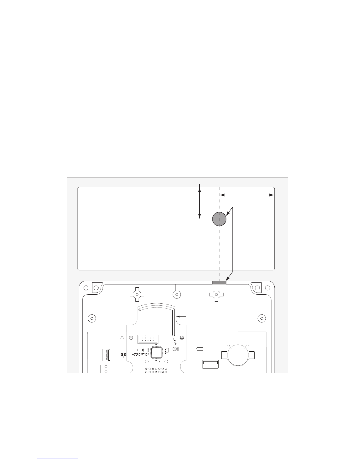
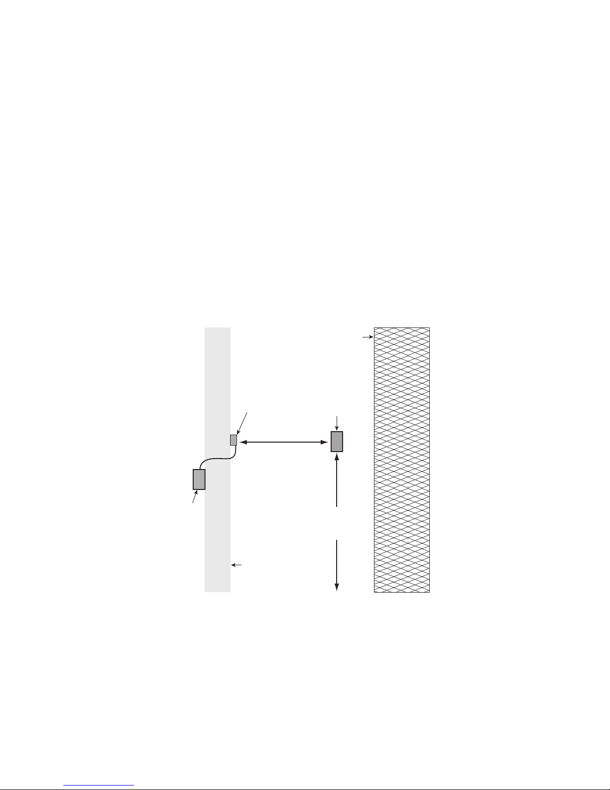
Terminate the coax whip at the WRI400
L Only applicable to installations using an optional remote antenna.
L To avoid damage to electronics inside the enclosure when drilling, use light
pressure so that the bit does not penetrate very far when it breaks through the
enclosure, or remove electronics from the enclosure before drilling.
1. Drill a Z\x” (13 mm) hole in the top of the WRI400 enclosure as shown to accommodate
the mounting of the coax whip to be connected to the WRI400 radio board.
2” (51 mm)
¹⁄₂” (13 mm) hole
1
USED ON CT5000 ONLY
PRIMARY SIDE
400 400
SIDE UP
DEBUG
USB
+3.3V
TX
GND
OPEN
1
WRI WSM CT5000
23394075_B
ICLK
IDAT
RB8
RB7
GND
VDD
MCLR
USB
THIS
MOUNT
BATTERY_HOLDER1
J3
TP25
TP24
TP23
TP22
TP21
LED1
LED2
J5
Top of WRI400 Enclosure
Radio Board
1” (25 mm)
1
1
PRIMARY SIDE
SIDE UP
DEBUG
USB
+3.3V
RX
TX
OPEN
1
1
23394075_C
ICLK
IDAT
RB8
RB7
GND
VDD
MCLR
USB
THIS
MOUNT
LED2
BATTERY_HOLDER1
J3
TP25
TP24
TP23
TP22
TP21
LED1
J5
2. Refer to the Optional Remote Antenna Module (ANT400) user guide for complete coax
connection instructions.
7 • Schlage • WRI400 user guide
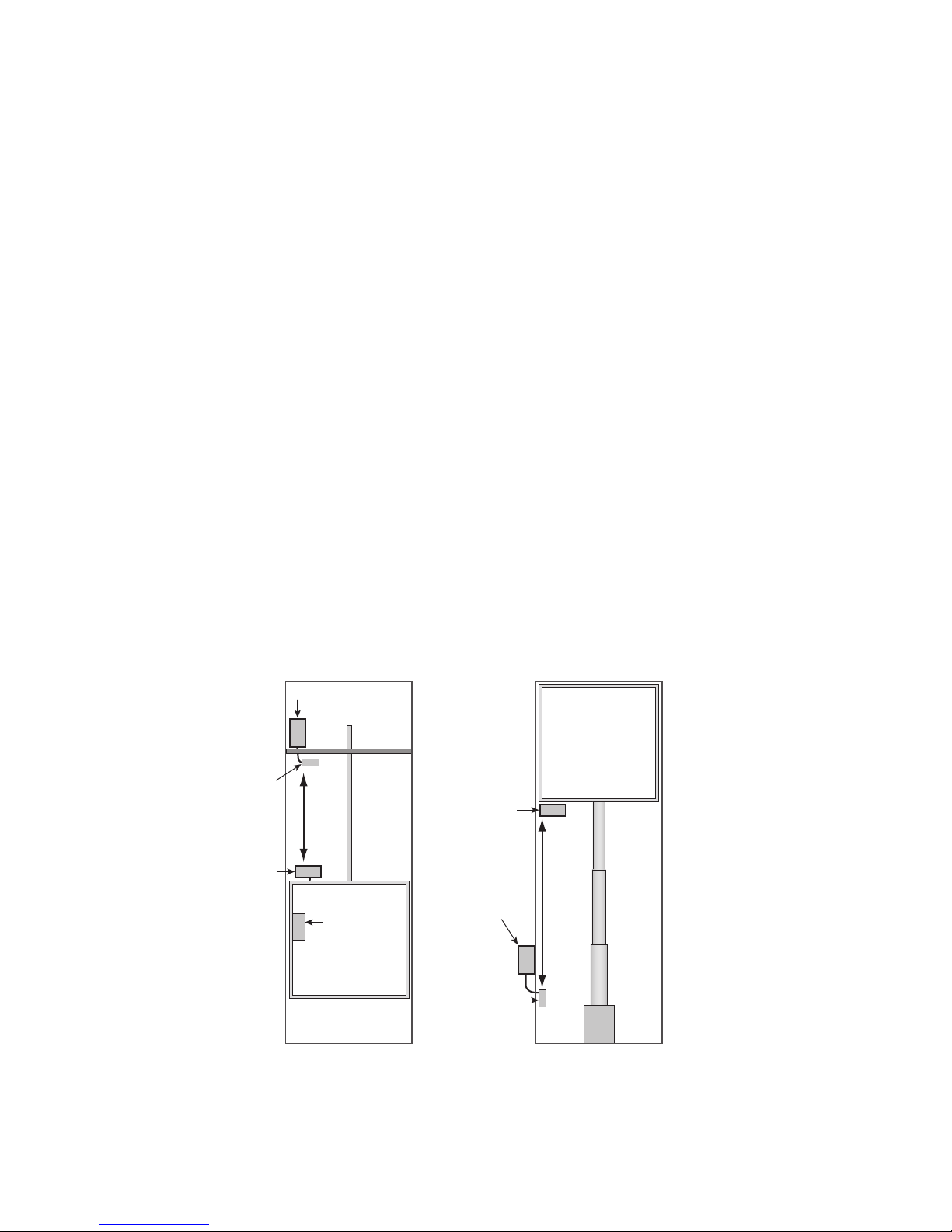
Outdoor gate applications
Follow the guidelines below for reliable performance between the WRI400 and PIM400 when
used to control an outdoor gate.
• When using the PIM400’s internal antenna mount the PIM400 at least 6 feet (1.8 meters)
away from the oor.
• If installing the PIM400 in a room with metal walls or metal mesh in the walls, a Remote
Antenna Module (ANT400) is required to be located outside of the room.
• Mount the WRI400 upright within a secured area in direct line-of-sight to the PIM400 (or the
antenna module).
• If the WRI400 to be controlled by this PIM400 is outdoors, install the PIM400 indoors
within a secured area on the inside of the building’s outer wall nearest the gate. Use a
remote antenna with the PIM400 and mount the antenna on the outside the building in
direct line-of-sight to the WRI400(s).
L If the WRI400 is mounted on a metal wall or wall with metal mesh, refer to page
9 for installation instructions.
• If a site uses more than one WRI400, install a PIM400 within direct sight of WRI400s
under its control. Maximum line-of-sight distance is 1000 feet (305 meters)* between
any WRI400 and PIM400. If necessary, use a separate PIM400 for each WRI400.
• Obstructions between the WRI400’s antenna and the PIM400’s antenna will decrease
the distance that they may be placed apart.
Direct Line of Sight
*
Maximum 1000 feet
(305 meters)
WRI400
PIM400
Building
Outside
Wall
Minimum
6 feet
(1.8 meters)
Gate
Remote
Antenna
Module
(ANT400)
*
Use of high-gain antenna (ANT400-REM-I/O+6DB) will improve range.
8 • Schlage • WRI400 user guide
Elevator applications
L The following elevator applications pertain to access control and not elevator control.
Follow the mounting location guidelines below for reliable performance between the WRI400
and PIM400 when used to control a typical cabled hoist or hydraulic elevator.
Cabled hoist machine installations with upper machine rooms:
• Mount the WRI400 on top of the cab, lying down if possible.
• Mount the PIM400 inside a secured area, e.g., within the secured elevator machine room.
• If required, mount a Remote Antenna Module (ANT400) on the ceiling of the shaft.
• Locate the PIM400 within range of the antenna module’s coax cable (15 cable feet
(4.5 meters)).
• Mount the antenna module with direct line-of-sight to the WRI400 throughout the entire
travel of the cab through the shaft. Ensure that structural members do not obstruct
line-of-sight to the WRI400.
Cabled hoist machine installations with lower machine rooms:
• Use a Remote Antenna Module (ANT400) with the PIM400 to prevent contamination of
the PIM400 from settled dust, oil, and debris.
Hydraulic machine installations
• Mount the WRI400 on the underside of the cab.
• Locate the PIM400 in a secured area, outside the shaft pit, where it will be free of
contamination from oil.
• If required, use a Remote Antenna Module (ANT400) with the PIM400.
• Locate the PIM400 within range of the antenna module’s coax cable (15 cable feet
(4.5 meters)).
• Mount the antenna module horizontally in the shaft pit, at a height where oil leakage and
debris cannot submerge it.
• The antenna module must have direct line-of-sight to the WRI400 throughout the entire
shaft. Ensure that structural members, including the ram, do not obstruct line-of-sight
to the WRI400.
Direct
Line
of
Sight
WRI400
PIM400
Elevator Cab
Remote
Antenna
UL listed
Card
Reader
Elevator
Shaft/Pit
Elevator
Machine
Room
Direct
Line
of
Sight
WRI400
PIM400
Elevator Cab
Remote
Antenna
Elevator
Shaft/Pit
Ram
Cabled Hoist Elevator Hydraulic Elevator
 Loading...