

Schlage VIP 5100 series Installation Manual
Form 57032 Rev. A
01-05-2004
VIP 5100 OPEN ARCHITECTURE CYLINDRICAL LOCK
INSTALLATION MANUAL
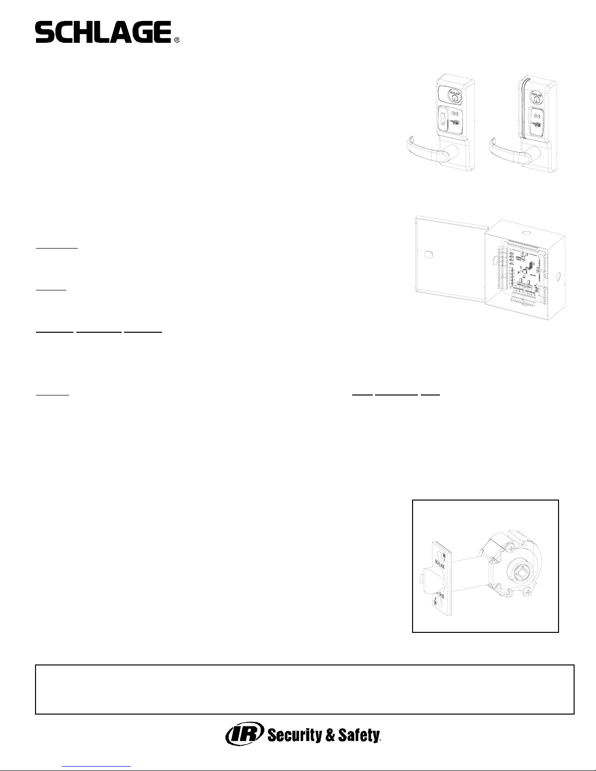
5100 CYLINDRICAL
LOCKSET - STANDARD
The VIP 5100 series lock is a microprocessor controlled, electromechanical locking system.
It is an open architecture product designed to interface with 3rd party panels ecompassing
all the features of the lock, reader, door status* and egress (rex/request to exit) indication in
one fire-rated piece of hardware. The 5100 employs a heavy-duty mechanical design tested
and complying with ANSI/BHMA grade 1 standards for performance and reliability. It is powered by 12 or 24 volts DC with only four wires required - two for power and two for communications. The lock communicates with a PIB (panel interface board) which communicates
with the panel as if it were separate components of an access control system.
Operationally, the outside lever is normally locked and the inside lever always retracts the
bolt to allow egress. Electronic access control is achieved by entering an”Access Credential”
(magnetic stripe card or Prox fob or card). The panel controls the lock through the PIB.
*Cylindrical model requires separate door status switch (included) to be installed in the door
and frame and connected to the VIP lock.
Please refer to all instruction manuals involved in the installation before you begin.
Functions
:
VIP 5196-FSA: Cylindrical, Fail Safe (unlocked)
VIP 5196-FSE: Cylindrical, Fail Secure (locked)
Models
:
MG: Magnetic stripe card reader
PX: HID Prox card reader
S
tandard Monitoring Switches:
DSM: Provides door status via data link to panel interface
KSM: Provides mechanical key use events via data link to panel interface
REX: Provides indication of inside lever use for request to exit input via data link
to panel interface
Options
:
T3: Track 3 card reader (data must be ABA track 2 format) - MG only
EXT: exterior use option - MG only (PX model has this standard)
KD: Keyed Different, includes Schlage Everest cylinder
KA: Keyed Alike, includes Schlage Everest cylinder
LC: Less Cylinder
SLB: 2-3/4” backset, 1/2” latch bolt
OLB: 2-3/8” backset, 1/2” latch bolt
ELB: 2-3/4” backset, 3/4” latch bolt
BEFORE YOU BEGIN:
Standard units are shipped from the factory to fit 1-3/4” doors. Verify the
door thickness. If the door is not 1-3/4” thick, verify that the door thickness
option was ordered or consult factory.
PRE-INSTALLATION CHECK:
AN OPEN ARCHITECTURE SYSTEM REQUIRES AT LEAST THREE COMPONENTS - A PANEL INTERFACE BOARD (PIB), AN ACCESS CONTROL PANEL
(BY OTHERS) TO WHICH THE PIB IS CONNECTED AND THE VIP LOCK. SEE
DOCUMENTATION FOR THE ACCESS CONTROL PANEL/SOFTWARE THIS
LOCK WILL BE USED WITH FOR ANY PRE-INSTALLATION TESTING REQUIREMENTS AND REMEDIES. REFER TO THE WIRING INFORMATION INCLUDED
WITH THE PIB FOR MORE INFORMATION.
PIB
PX MG
Door Thickness Kits:
Available in 1/8” increments from 1-3/8” to 2-1/2”
This device complies with part 15 of the FCC rules. Operation is subject to the following two conditions: (1) this device may
not cause harmful interference, and (2) this device must accept any interference received, including any interference that may
cause undesired operation. Changes or modifications not expressly approved by the party responsible for compliance could
void the user’s authority to operate the equipment.
Form 57032 Rev. A
01-05-20042
VIP 5100 OPEN ARCHITECTURE CYLINDRICAL LOCK
INSTALLATION MANUAL
WIRE RACEWAY REQUIRED:
It is best to have the wire race way prepared at the door and
frame manufacturer. If this has not been done there are two
suggested preparation methods for making wire paths for the
FSE and FSA models in the field. Select method A or B;
depending on the door and frame circumstances, one may be
better than the other. Consult door manufacturer with any ques-
tions regarding agency listings with respect to fire integrity.
METHOD A:
1. Prep door and frame according to standard template.
2. Determine location of standard 1 inch wire harness through
hole and mark centerline of hole on hinge side of door.
3. Using appropriate drilling jig and drill bits, drill 3/8” or 1/2”
wire race from edge of hinge side into standard wire harness
through hole.
4. Install electric hinge or door cord and run wires.
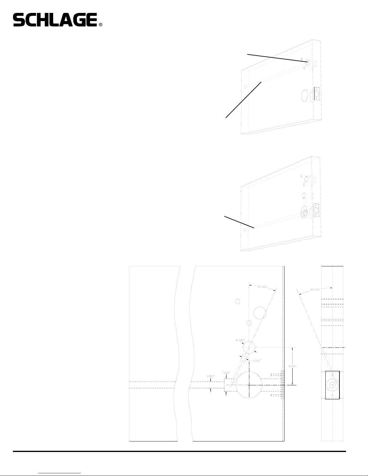
METHOD B:
1. Prep door and frame according to standard template.
2. Using a 1” drill bit, continue the 1” latch hole through retractor
hole to a depth of 5”. This will allow room for the wiring to pass
around the retractor.
3. Using appropriate drilling jig and drill bits, drill 3/8” or 1/2”
wire race from the latch hole through the door toward the hinge
side. It is not necessary to continue drilling the hole through the
hinge side.
4. Measure up 3 inches from the center of the 2 1/8” retractor
hole and drill a 1 inch through hole on center as shown below.
5. Using a 3/8 inch drill bit, place the tip of the drill into the 1”
wire hole drilled in step 3 and aim at the angles shown. Drill
down and toward the hinge side to intersect the 1” latch hole
(where it was continued in step 2.
4. Install electric hinge or door cord and
run wires.
Note: this method offers the advantage of
not having holes exiting the door edges.
If a door cord is used the door cord wire
hole can be cross drilled into the long
wire race.
WIRE RACE
WIRE RACE
STANDARD WIRE
HARNESS THROUGH
HOLE
METHOD B:
METHOD A:
FSE & FSA HARD WIRED MODELS
REQUIRE WIRING TO BE RUN TO
THE LOCK PREP FROM THE HINGE
SIDE. BELOW IS A SUGGESTED
METHOD TO DO THIS. A DOOR CORD
OR ELECTRIC HINGE OR POWER
TRANSFER DEVICE IS USED TO
ROUTE WIRING FROM FRAME TO
DOOR. NOTE THAT WHEN USING AN
ELECTRIC HINGE IT IS RECOMMENDED THAT THE POWER WIRES
BE DOUBLED OR TRIPLED UP (ON
BOTH THE POSITIVE AND GROUND
LEGS) TO AVOID SIGNIFICANT VOLTAGE DROP THROUGH THE THIN
WIRES IN THE HINGE.
Form 57032 Rev. A
01-05-20043
VIP 5100 OPEN ARCHITECTURE CYLINDRICAL LOCK
INSTALLATION MANUAL
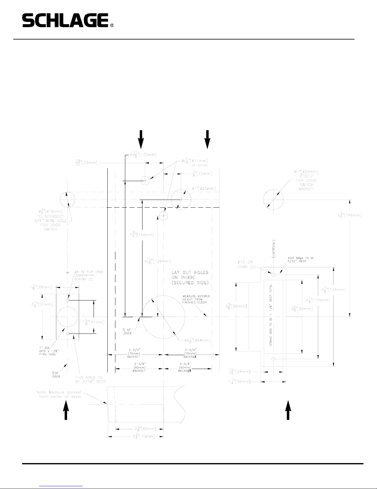
1. PREP DOOR AND FRAME:
A. Determine door hand and correct backset.
B. Mark the horizontal and vertical centerlines for the lockset, latch and strike.
C. Place template on inside of door (opposite the side that the keypad/reader will be on). Line up the correct reference lines
on the template with the edge of the door. The centerline on the door should line up with the vertical centerline of the template.
D. Drill holes as described by template.
DOOR EDGE (LATCH)
FRAME (STRIKE)
DOOR FACE (LAY OUT ON INSIDE)
 Loading...