

Schlage PS906 Installation Instructions Manual
*44487049*
44487049
Power Supply
To avoid risk of electric shock, turn off AC power before
installing or servicing PS906 power supply
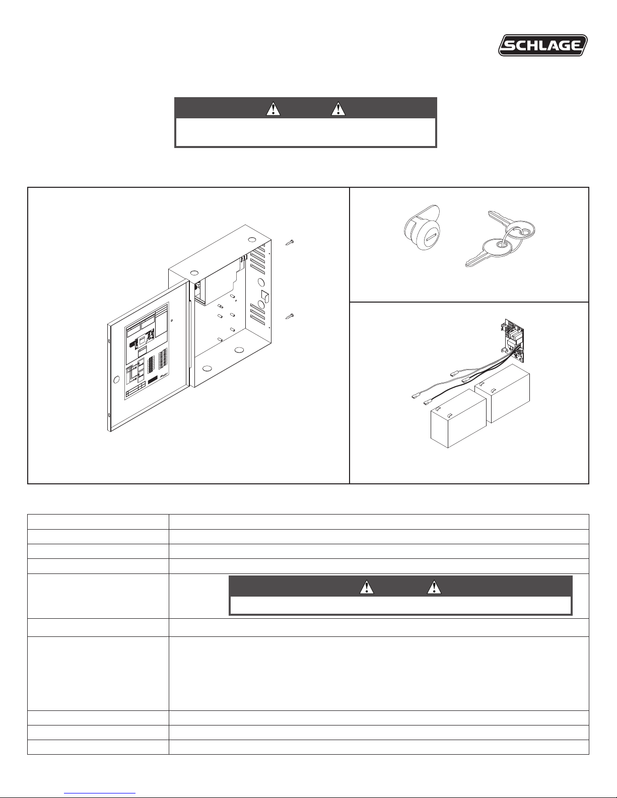
These instructions cover the following parts:
WARNING:
!
WARNING:
!
DANGER
!
F1
DANGER:
!
PS906
Installation Instructions
DANGER
900-KL Keylock (optional) - Page 2
PS906 Power Supply - Pages 1-3
900-BB Battery Backup (optional) - Page 3
PS906 Power Supply Specications:
Input 120/240 VAC, 2.4 A, 50/60Hz, High Voltage Class 1 Wiring Required
Output 6 Amp DC @ 12/24 VDC
Enclosure 14” H x 12” W x 4” D (8 knockouts, 1/2” or 3/4” )
Temperature Range 32°-120° F (0°- 49° C)
Fuse F1, T6.3A
250 VAC
For protection against risk of re, replace fuse with same type and rating
Compliance UL 294, ULC-S318, RoHS, & FCC Part 15, Class 1 Output
Compatible Boards
(Optional, 3 boards maximum)
900-2RS
900-4R
900-4RL
900-8F
900-8P
Fire Alarm Input Board (Optional) 900-FA (Requires one option board above)
Battery Backup Board (Optional) 900-BB
AC Monitor Output Form C Contacts, 30 VDC, 1 Amp, Resistive Load
CAUTION
INST. INSTRUCTIONS - 24125007
INST. INSTRUCTIONS - 44487106
INST. INSTRUCTIONS - 44487080
INST. INSTRUCTIONS - 44487106
INST. INSTRUCTIONS - 44487106
INST. INSTRUCTIONS - 44487072
INST. INSTRUCTIONS - 44487064

Mounting notes
The PS906 must be installed in accordance with the article 760 of the National Electrical Code or NFPA 72 Canadian Electrical Code, or
any other applicable codes.
Install the PS906 indoors within the protected premises.
Check national and local codes for additional installation requirements.
Enclosure must be rmly mounted to a solid surface using hardware suitable for the surface.
1 Mount power supply
1a Mark 2 Top Holes 1b Secure Enclosure with 4 Screws
x
2 Secure enclosure door
If No Keylock
Enclosure will be secured with 2 screws
as shown (done as last step)
x
Board not shown
for clarity
If Keylock
Remove knockout and insert key cylinder, then slide in clip
OR
a
b
 Loading...