

Schlage PIM400-TD2 User Manual
*P516-096*
P516-096
PIM400-TD2
User guide for Panel Interface Module PIM400-TD2
Para el idioma español, navegue hacia www.allegion.com/us
Pour la portion française, veuillez consulter le site www.allegion.com/us

2 • Schlage • PIM400-TD2 user guide
Contents
Overview ........................................................................................................................... 3
Getting started ..................................................................................................................4
Features and components ................................................................................................ 5
Model specications .........................................................................................................6
Installation .........................................................................................................................6
Determine the location ..................................................................................................6
Pre-installation test........................................................................................................6
Installation ..................................................................................................................... 7
Mount the PIM400-TD2 ................................................................................................. 7
Wire routing ................................................................................................................... 8
Cable/wire specications ..............................................................................................8
PIM400-TD2 to ACP connection ....................................................................................... 9
Typical PIM400-TD2 to ACP wiring diagram .................................................................9
Optional remote antenna ................................................................................................12
Link mode .......................................................................................................................12
Schlage Utility Software (SUS) ....................................................................................... 12
Reset to factory defaults ................................................................................................. 12
DC power ........................................................................................................................ 13
Complete the installation ................................................................................................13
Troubleshooting ..............................................................................................................13
FCC/IC statements.........................................................................................................14
To comply with FCC and Industry Canada RF radiation exposure limits for general population,
the antenna(s) used for this transmitter must be installed such that a minimum separation
distance of 20cm is maintained between the radiator (antenna) and all persons at all times
and must not be co-located or operating in conjunction with any other antenna or transmitter.
This product is compliant of UL 294 and ULC S319 standard. This product’s compliance
would be invalidated through the use of any add-on, expansion, memory or other module
that has not yet been evaluated for compatibility for use with this UL Listed product, in
accordance with the requirements of the Standards UL 294 and ULC S319. This product has
been evaluated for ULC-S319 Class I.
3 • Schlage • PIM400-TD2 user guide
Overview
This manual describes the operation and interaction of the Schlage PIM400-TD2 with Access
Control Panels (ACPs) and Wireless Access Point Modules (WAPMs). The PIM400-TD2 is a
product in the AD-400 Wireless Panel Interface Module (WPIM) category. The PIM400-TD2
is wired to the Access Control Panel.
• Connect the PIM400-TD2 to external power using a UL294 listed power supply for
UL installations, and a ULC S318/ULC S319 listed power supply for cUL installations.
Example power supplies include Schlage PS902, PS904, PS906.
• Installation location is determined by the location of the WAPM. The PIM400-TD2 is
ideally installed very close to the access control panel.
• The PIM400-TD2 communicates to the WAPM(s) using radio frequency (RF).
• The WAPM is installed at the access point where access will be controlled and/or
monitored.
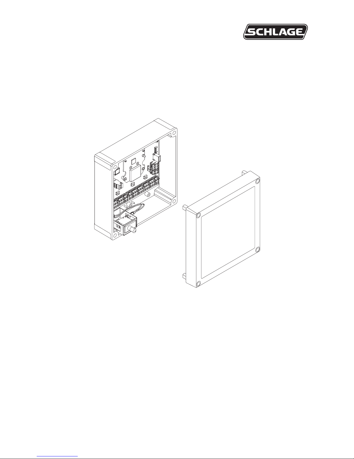
• The PIM400-TD2 enclosure is NEMA type 4.
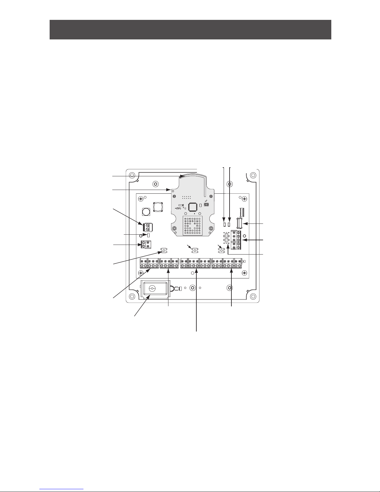
Access Point 1
Status Signals
(J10)
Access Point 2
Control Signals
(J7)
Access Point 1
Control Signals (J8)
Access Point 2
Status Signals
(J11)
Power/Tamper LED (D3)
Link 2
Button
Link 1 Button
Tamper Switch
Connector (J1)
J19/J20
not used
Power
Connector (J2)
Reset
(S1)
USB Connector (J9)
J5 not used
Tamper
Switch
Internal Antenna
Antenna Module
Receive
LED (D4)
Transmit
LED (D5)
PIM400-TD2 printed circuit board assembly (PCBA)

4 • Schlage • PIM400-TD2 user guide
Getting started
The following is an overview of the steps required to set up the PIM400-TD2:
1. Install the WAPM (AD-400, WPR400, etc). See the installation guide that came with the
WAPM or visit www.allegion.com/us (see Support>Schlage Electronics>Electronic Locks
Technical Library) for more information.
2. Make sure the PIM400-TD2 is located to allow for optimum RF signal transmission.
See Determine the location on page 6 for more information.
3. Before installing the PIM400-TD2, check for proper communication function and linking
with WAPM(s). See Pre-installation test on page 6 for more information.
4. The PIM400-TD2 has been evaluated for UL compliance in indoor applications only.
5. Make sure to follow unique installation procedures if installing on an indoor metallic
wall. Refer to Mount the PIM400-TD2 on page 7 for more information. Consult the
Schlage Utility Software (SUS) user guide for information about conguring the
PIM400-TD2 and the WAPM.
6. Familiarize yourself with the information contained in this user guide.
This user guide is for the PIM400-TD2 only.
Save this user guide for future reference.

5 • Schlage • PIM400-TD2 user guide
Features and components
Feature Description
PIM400-TD2
status
Power and tamper status is indicated at the PWR/Tamper LED (D3).
The LED is steady green when power is on and the tamper is inactive (cover
is on), and blinking green when the tamper switch is activated (cover is off).
Access point
link and
status
The PIM400-TD2 overall status is communicated by a red/green LED for
each access point.
Red LEDs communicate real time and trouble status. The LED is off when
the WAPM is linked; the LED is on when the WAPM is not linked.
Real time status: D40 = access point 1, D43 = access point 2
Trouble status: D1 = access point 1, D2 = access point 2
The PCB is marked with LED locators D1, D2, D40 and D43.
Each access point has clock (CLK) and data (DATA) LEDs that indicate card
and keypad data communication from the PIM400-TD2 to the ACP.
Reset switch
Press the reset switch (S1) if the PIM400-TD2 does not seem to operate
properly.
Tamper
switch
The tamper switch senses if the PIM400-TD2 enclosure cover is open or closed.
If closed, the D3 LED is steady green and extended unlock works, if enabled.
If open, the D3 LED is blinking green and extended unlock does not work
even if enabled.
Component Description
Access
control panel
connection
The PIM400-TD2 connects two WAPMs to the ACP.
WAPM (Door) 1 connects through the access point 1 connections on J8 and
J10 to the ACP, and WAPM (Door) 2 connects through the access point 2
connections on J7 and J11.
Power
connector
The PIM400-TD2 power input (J2) is non-polarized. If power is lost or cycled,
upon restoring power, the PIM400-TD2 will continue operation with the same
conguration and linking information. There is no need to re-congure
or re-link.
 Loading...